i
國
立
交
通
大
學
資訊科學與工程研究所
碩
士
論
文
毫米波無線個人通訊網路
結合中繼點選擇與排程之演算法
Joint Relay Selection and Scheduling Algorithm for
Inter-piconet Communications in Millimeter Wave Wireless
Personal Area Networks
研 究 生:劉人僖
指導教授:趙禧綠 助理教授
ii
毫米波無線個人通訊網路結合中繼點選擇與排程之演算法
Joint Relay Selection and Scheduling Algorithm for Multi-piconet
Communications in Millimeter Wave Wireless Personal Area Networks
研 究 生:劉人僖 Student:Jen-Hsi Liu
指導教授:趙禧綠 Advisor:Hsi-Lu Chao
國 立 交 通 大 學
資 訊 科 學 與 工 程 研 究 所
碩 士 論 文
A ThesisSubmitted to Institute of Computer Science and Engineering College of Computer Science
National Chiao Tung University in partial Fulfillment of the Requirements
for the Degree of Master
in
Computer Science
June 2011
Hsinchu, Taiwan, Republic of China
iii
摘要
60 GHz 頻段通訊被認為是深具潛力的高速家庭及區域網路無線通訊之前瞻 技術。由於訊號衰減性高且載波穿透性低,資料傳輸範圍相當有限。在 802.15.3c 網路中,使用波束形成(beamforming)及指向性天線來加強其傳輸功率及資源使 用效率,但改善有限。由於傳輸範圍僅 10 公尺,因此在一空間中可能存在多個 網路,在同一網路間傳輸對為 intra-piconet flow,而跨網路傳輸的傳輸對稱為 inter-piconet flow,本論文的研究目的為在 60 GHz 免執照頻段之高速通訊系統之 MAC 層技術,有效利用其指向性天線特色與定位資訊,在網路內尋找適合傳輸 的時機以及中繼者(relay)幫忙轉運資料,並設計一時空重複利用度(time-spatial reusability)最佳的排程機制,以達到增加系統吞吐量及多個網路間溝通效率之目 標。 本論文首先設計ㄧ模型來最佳化本研究欲解之問題,並推算出此解的複雜度, 由於最佳化求解通常為 NP 問題,因此本文提出簡化演算法來求得一近似最佳解。 演算法主要是分成兩個部分,第一部分為了減化演算法的複雜度,先進行網路內 傳輸對 intra-piconet flow 的排程,期望用最少的時間傳完 intra-piconet flow。第 二部分則是根據第一階段的排程結果,定義 interference-free、concurrence-restricted extent、concurrence index,並設計適當的中繼點選擇及排程 演算法,使得在增加傳輸時間最少的情況下完成所有傳輸對的傳輸。
最後以模擬結果呈現在任意選擇中繼點的情況下與本篇所提之演算法作比 較,比較系統效能以及通道再利用率,結果顯示所提出之演算法,可藉由適當的 中繼點選擇及排程的交互作用提升通道再利用率,並有效改善系統的整體效能。
iv
Abstract
The unlicensed 60 GHz spectrum is very attractive for the broadband wireless networks because it can support the multi Gbs transmissions with 7 GHz bandwidth. Due to the oxygen absorption and path loss, the transmission range is limited to several meters. Operating in the 60 GHz band, IEEE 802.15.3c and 802.11ad networks use directional antenna and beamforming technique to avoid high propagation attenuation and path loss, and improve the overall system throughput by exploiting spatial channel reuse. In our thesis, we introduce the necessity and design challenges of inter-piconet communications. First, we develop a formulation for optimal relay selection and scheduling to minimize the inter-piconet flows’ transmission time. Since the optimization is a NP problem, our research is to find a heuristic algorithm to solve. Based on our observation, we propose a joint design of relay selection and scheduling with greedy concept. Specifically, we define “interference-free”, “concurrence-restricted extent”, and “concurrence index” for properly selecting relays to improve the degree of spatial channel reuse. The designed scheduling algorithm consists of two phases: intra-piconet flow scheduling and inter-piconet flow scheduling. After performing phase 1 operations, intra-piconet flows are scheduled and the total required channel time is known. The phase 2 operations are to use the least channel time extension to schedule all inter-piconet flows. We evaluate our algorithm through simulations. The results show that the joint algorithm performs well and does achieve its objectives.
v
致謝
感謝指導教授趙禧綠教授兩年來的諄諄教誨。想當初因為基礎不紮實,期許 自己進入研究所後可以累積專業知識並培養研究能力,儘管現在仍有許多不足, 但非常感謝教授一直以來給予學生相當多的關心及指導,讓我獲得很大的進步。 也感謝老師鼓勵學生參與論文投稿,讓學生有難得的機會可以和外國學者交流。 另外感謝實驗室的學長姐們,在我研究的過程中給予許多寶貴經驗,要特別謝謝 銘佩學姊、子綺學姊,在我對研究方向感到徬徨時適時給予題點,幫助我釐清問 題。也謝謝一起同甘共苦兩年的碩二同學們,謝謝你們給予我的幫助和鼓勵,成 為我強大的靠山,讓我在面對困難挑戰時可以堅持下去。感謝碩一的學弟們,雖 然和大家相處的時間不多,但是你們幽默詼諧的談話,在我埋頭進行論文撰寫過 程中帶來很多歡樂,也多虧你們的幫忙,讓我們在最後能專心進行口試的準備。 最後,我要謝謝我的家人和好友,因為有你們的支持和幫助,我才能無後顧 之憂的專心於我的研究,特別感謝 Rachel,不管在各方面都給我很強大的支援。 祝福所有人,事事順心、平安喜樂!vi
Contents
摘要 iii
Abstract iv
致謝 v
List of Figures vii
List of Tables vii
Chapter 1. Introduction ... 1
1.1 An Overview of IEEE 802.15.3c Network ... 1
1.2 Problem Description and Objectives ... 4
1.3 Objective ... 6
1.4 Thesis Organization ... 6
Chapter 2. Related Work ... 7
Chapter 3. Problem Formulation ... 11
3.1 Framework Objective ... 11
z Constraints for Basic Relay Selection ... 13
z Constraints for Optimal Relay Selection and Flow Scheduling .... 14
Chapter 4. The Designed Joint Relay Selection and Scheduling Algorithm 16 4.1 CTA‐based relay selection ... 16
4.2 Scheduling Algorithm ... 22
Chapter 5. Performance Evaluation ... 27
5.1 Simulation environment ... 27
5.2 Simulation Result ... 28
Chapter 6. Conclusions and Future Work ... 33
vii
List of Figures
Figure 1.1 Piconet architecture ... 1
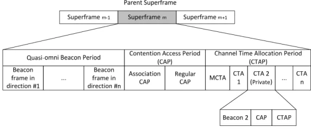
Figure 1.2 Superframe format of IEEE 802.15.3 MAC protocol ... 3
Figure 1.3 An illustration of inter-piconet flows, intra-piconet flows, and relay candidates ... 5
Figure 4.1 Interference-free: an example ... 17
Figure 4.2 Concurrence restricted extent: an illustrative example ... 19
Figure 4.3 Set of relay candidates: an illustrative example ... 21
Figure 4.4 Pseudo code of joint relay selection and scheduling algorithm ... 25
Figure 4.5 The scheduling results of the example in Fig. 4.3 ... 26
Figure 5.1 The utilized channel time v.s. the number of data flows ... 31
Figure 5.2 The system throughput v.s. the number of flows upon 30° and r = 1 Gbps……….31
Figure 5.3 The performance of spsatial channel reuse v.s. beam width ... 32
Figure 5.4 The utilized channel time v.s. the number of data flows (Optimized v.s. Heuristic)... 32
List of Tables
Table 3.1 Symbols and notations used in formulation ... 131
Chapter 1. Introduction
Millimeter wave wireless personal area networks (mmWave WPANs) operating in the 60GHz band have attracted much attention recently due to its high-data-rate transmission capability (over 3Gbps) so that numerous high-bandwidth-demand indoor wireless applications become possible. Examples of such applications include uncompressed transmission of high definition TV (HDTV), high speed internet access and wireless gigabit Ethernet. Existing wireless local area networks (WLANs) and wireless personal area networks (WPANs) cannot support these applications due to the required data rate is far beyond their capabilities. As a result, mmWave WPAN has become a major trend in the short range communication systems, leading to active research and standardization efforts in this area such as the IEEE 802.15.3c [1, 2] and 802.11ad [3].
1.1 An Overview of IEEE 802.15.3c
Network
The fundamental unit of an mmWAVE WPAN is named as a piconet, which is formed in ad-hoc fashion as shown in Fig.1.1. Among a group of nodes, one of them is designated as the piconet coordinator (PNC). The PNC is responsible to admit devices to be the members of the piconet, keep their information for maintaining the
2
piconet, announce the existence of the piconet, and synchronize communications among devices in the piconet. In addition, the PNC manages access control of the remaining nodes. The necessary control information is embedded in beacon messages. Once power-up, a DEV remains in passive scanning mode for a period of time. If no beacon is heard during that time, then the DEV assumes the role of a PNC and begins transmitting beacons. Upon receiving a beacon message, nodes are aware of the existence of the PNC, and they learn when and how to access the channel. The channel time is divided into a sequence of superframes, and each superframe consists of three portions: beacon, contention access period (CAP) and channel time allocation period (CTAP). Each superframe starts with a beacon, followed by a CAP. The channel access of CAP is governed by the Carrier-Sense Multiple Access/Collision Avoidance (CSMA/CA) method. The remaining time in a superframe is CTAP, which provides time division multiple access (TDMA) type of communications. The CTAP comprises one management channel time allocation (MCTA) and multiple channel time allocations (CTAs). MCTA is for nodes to issue their transmission requests to the PNC, while CTAs are for nodes to transmit data frames. The superframe format is shown in Fig. 1.2.
For two piconets, if they are close to each other so that the coverage are overlapped, we call a piconet is a dependent piconet of the other (parent piconet). As a dependent PNC is outside the parent piconet, the dependent piconet is also named neighbor piconet; otherwise, it is a child piconet. In 802.15.3 standard, if the parent PNC permits the formation of a dependent piconet and there is sufficient channel time available, the parent PNC shall allocate a CTA (also named private CTA) to the dependent piconet as its superframe. A neighbor piconet, for example, divides the private CTA into BP, CAP, and CTAP as shown in Fig. 1.2. However, DEVs equipped with directional antennas in 802.15.3c can transmit multiple data flows in a CTA
3
without interference, so we prefer each piconet operates its own superframe instead of sharing superframe. That is, we schedule flows transmitting within a piconet and across piconets both in normal CTAs and every piconet parallel runs its superframe simultaneously. Piconet coordination was introduced in [4] based on information exchange via an intermediate DEV, thereby making superframe synchronization possible. Beacon alignment was meanwhile proposed to avoid beacon interference since the beacon is important for piconet synchronization.
In [5, 6], the authors designed a scheduling algorithm considering positioning, axis alignment, and resource allocation for an IEEE 802.15.3c piconet. First, a network coordinator of the piconet (i.e., PNC) determines coordinates of each joined devices. Upon knowing each device’s coordinates and LOS flows’ information, the PNC allocates resources (i.e., channel time) to managed devices to maximize time-and-spatial reusability. Flows that will not interference with each other can be scheduled to transmit simultaneously. The scheduling algorithm deduct the total transmission time with the same amount of data so that the system resource can be allocated effectively. In this thesis, we extend the previous work to perform in
4
multiple piconets’ communication. Upon knowing the locations of all member DEVs, the neighbor PNCs can share their information and one PNC (i.e. main PNC) allocates a good timing for the multiple piconets’ communication as well as assigns the most suitable relay node to transmit efficiently.
1.2 Problem Description and Objectives
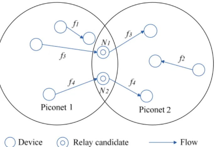
Because of the features of short wave length, high path loss, and high oxygen absorption, the transmission range of a node is restricted to be less than 10 meters. Therefore, an mmWAVE WPAN may consist of multiple piconets, and the support of inter-piconet communications is essential for data deliveries. One feasible approach for inter-piconet communications is “relaying”. The concept of relaying is simple, while its design is complicated. This is due to the beamforming technique [7]. Beamforing utilizes multiple antenna elements to form a beam toeard a certain duration with increased signal strength, and the significant signal degradation can be compensated. With beamforming technique, nodes can only transmit and receive signals at a specific direction, which means exploiting spatial channel reuse among data flows can improve scheduling efficiency and channel utilization. How to select relays to improve the degree of spatial channel reuse, and increase the system throughput are our major concerns. To this design goal, scheduling should be designed jointly with relay selection. We use Fig. 1.3 as an example to illustrate how relays affect the scheduling efficiency. Herein we name a flow whose sender and receiver locate in different piconets an “inter-piconet flow”; otherwise, it’s an “intra-piconet flow”. In Fig. 1.3, and are intra-piconet flows; and are inter-piconet flows.5
Considering piconet 1, and are two available relays of and . If both and select (or ) to be the relay, two CTAs are utilized (one is for and the other is for ) for data transmission. Another assignment is that and have distinct relays. Considering that is the relay of and is the relay of , since ‘s reception is interfered with , these three flows still utilize two CTAs (one is for and , and the other is for ) to transmit data. If and select and
respectively as the relays, , and are interference-free flows and can be scheduled in the same CTA.
In this paper, a joint relay selection and scheduling algorithm is designed for mmWAVE WPANs. The objectives of the designed joint algorithm are to exploit the characteristic of beamforming technique, maximize the degree of spatial channel reuse, and increase the performance of system throughput.
Scheduling intra- and inter-piconet flows with relay selection is a NP problem obviously. To simplify our problem, our algorithm can be divided into two phases: intra-piconet flow scheduling and inter-piconet flow scheduling. In phase 1, we use a greedy algorithm to schedule intra-piconet flows, and derive a nearly shortest CTAP which compost of CTAs with flow transmission. In phase 2, based on the result of phase 1, we modify our objective to minimize the extension of the CTAP to transmit
Figure 1.3 An illustration of inter-piconet flows, intra-piconet flows, and relay candidates
6
both kinds of flows. We design a relay selection rule to find the suitable relay allocation to meet our target while scheduling the inter-piconet flows.
1.3 Objective
In this thesis, we formulate a framework to find the optimized our problem and design a joint algorithm of relay selection and scheduling for IEEE 802.15.3c networks. The contributions of our approach are summarized as follows.
(1) We define rules for relay selection, which is one of the key conditions to improve the degree of spatial channel reuse.
(2) By taking transmission and reception beam patterns into consideration, the proposed verification rules of concurrent transmission most exert the advantage of beamforming technology.
(3) Upon all intra-piconet flows been scheduled, our designed joint algorithm uses the least channel time extension to do inter-piconet flow scheduling.
1.4 Thesis Organization
The thesis is organized as follows. In Chapter 2, we study the related work. The optimization framework is formulated in Chapter 3. In Chapter 4, we present the designed joint relay selection and scheduling algorithm. Simulation results are presented and discussed in Chapter 5. We summarize and conclude the work in Chapter 6.
7
Chapter 2. Related Work
Research issues recently proposed of 60 GHz communication include physical implementation and system architecture design, beamforming technical design, effective performance analysis and improvement, relay selection, and resource allocation. Our thesis focuses on the resource management and relay selection between multi-piconet communications.
In IEEE 802.15.3 standard, the PNC uses conventional scheduling scheme that allocating a unique CTA to one data flow and the interference-free transmission is guaranteed. The scheduling scheme does not benefit from the usage of beamforming technology and spatial reuse so the system throughput in 802.15.3 WPAN has room for improvement. An enhanced IEEE 802.15.3 traditional scheduling scheme to support simultaneously operating piconets (SOPs) is proposed in [8]. The throughput is limited because the same superframe is shared by the dependent piconets as we mentioned in chapter 1; therefore, they defined the CTAs adaptively as normal CTAs and public CTAs that mitigate the inter-piconet interference and enhance the efficiency. Against to traditional superframe sharing configuration, each dependent piconet maintains its own superframe. To avoid beacon collisions in the overlapped area, the timing of all existing superframes are informed by operating piconet coordination and beacon alignment. As for interference occurred in CTAP, the PNCs schedule their intra-piconet flows into the normal CTAs, and these flows can transmit simultaneously; the PNCs allocate the public CTAs interlaced to transmit the inter-piconet flows. However, blocking the time interval in one piconet while the inter-piconet flows transmit in the other piconet is not efficient, so we do some modification that two flows can be scheduled in a CTA if no interference happened regardless of the flow types.
8
A randomized exclusive region (REX) based scheduling was introduced in [9, 10] to explore the spatial multiplexing gain in mmWave WPANs. The paper derived the exclusive region (ER) based on the use of omni- or directional antennas to allow concurrent flows transmission that are favorable in terms of per flow throughput and network throughput. Every receiver of a flow can draw its ER by computing a mainlobe and sidelobe of gain. If two flows are mutually outside each other’s exclusive regions, the flows can be scheduled to the same time duration to transmit. In REX, one flow is selected to be scheduled in a time slot; then, all remaining flows are verified according to the ER condition to discover spatial channel reuse-capable flows. The paper proposed an effective scheduling idea, but the PNC has to measure the channel gain to manage those flows. Though concurrent transmission is considered, inter-piconet communications and relay selection are not addressed.
Effective throughput of mmWave WPAN deploying relay was studied in [11]. Taking the impact from concurrent transmission into consideration, they proposed a deflection routing algorithm to maximize the effective throughput. By collecting the co-channel interference (CCI) periodically, the PNC maintains a table consisting of all the potential CCI to and from each and every link, and the PNC determines the suitable relay node and timing for requesting flows. In [12], the authors further formulated the scheduling problem and transfer this problem as a max-weight matching problem of a bipartite which can be solved by Kuhn-Munkres algorithm. However, devices send periodical probing signals so that the overhead gained inevitably. The contributions of these papers only work on the intra-piconet flows, and they do not feature the characteristics of directional antenna. [13] classified communications into two categories: direct path and relay path, and propose a deflection routing scheme. Both share the channel resource when signal-to-noise-plus-interference ration (SINR) of a receiver is acceptable. This
9
method improves the effective throughput by sharing time slots for direct path with relay path. The authors also propose Virtual Time-Slot Allocation (VTSA) to allow multiple flows concurrently transmitting in per slot basis. By maintaining the CCI table, the PNC assign the flows with less CCI value to share the same CTA. The CTA sharing the same channel resource with primary CTA is named a virtual CTA. The CTA is reusable and the throughput is improved. PNCs collect the information of co-channel interference to do relay selection, while the cost of probing channel statuses is high.
In [14], the authors proposed a joint link scheduling, channel assignment, and routing scheme for the 60 GHz multi-channel wireless mesh networks with directional antennas. They first designed a linear programming framework to model the network throughput of multi-channel multi-radio wireless mesh network and then study the routing optimization problem. It also proposed a heuristic greedy algorithm to obtain a feasible solution to approximate the optimal network throughput. Te greedy algorithm went to estimate the flow rate of each link on a channel in a CTA and schedule the link flow every CTA. Once collecting every possible link and channel information in the mesh network, the PNC will assign first flow to the channel that can provide maximum flow rate and assign next flow with second highest rate that would not interfere to those scheduled flows in the same time slot. This paper considered multiple channel assignment which is not the issue in our research.
Since the duration of superframe is not fixed but limited to 20 ms, the time division also plays a role in improving system throughput. In [15], the paper studied the throughput of the 802.15.3c WPAN system that is based on the hybrid multiple access of CSMA/CA (CAP) and TDMA (CTAP). From the analysis, the authors found that the throughput is significantly affected by the access time of CAP even if data transmission is mainly performed in CTAP. A tradeoff occured while a large access
10
time of CAP could reduce data transmission collisions; however, it would lead to degradation in the throughput since the data transmission time in CTAP was reduced relatively. Otherwise, lower the access time of CAP would not benefit the system throughput. The increasing data transmission collisions along with the shorter CAP would also lead to a reduction in the throughput due to an increase in the unused data transmission time in CTAP because of the failure of data transmission channel release in CAP. The paper provided the approximated optimum access time of CAP with different contending devices for maximizing the throughput. Moreover, it introduced throughput improvement through a reduction in the failures of data transmission channel release. In our simulation part, we set our parameters refer to the analysis result of this paper to gain our throughput.
11
Chapter 3. Problem Formulation
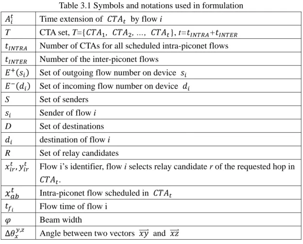
In this section, we formulate a non-linear programming framework to find the optimized relay selection and flow scheduling which minimize the extension of total transmission time and maximize the system throughput. Our proposed framework is applicable to the muti-piconet communications with directional antennas and time-sharing in a superframe. We first define our object and then develop the constraints. The symbols and notations we used are listed in Table 3.1..
3.1 Framework Objective
As we mentioned in Chapter 1, our algorithm is divided into two phases. In phase 1, we optimally schedule intra-piconet flows and minimized the CTAP. After scheduling all intra-piconet flows, we can derive CTA sets which contain the concurrent transmission intra-piconet flows within a CTA and the CTA duration. We do not know how many CTA sets will be used finally, so we allocate every hop of all inter-piconet flows a virtual CTA of which the duration is initially zero at first. The duration of the virtual CTAs will be assigned after we schedule the flows in. We assume there are t CTAs that t= + and equals to the sum of the inter-piconet flows.
Here we list the assumptions and givens before optimization.
(1) The piconet path of an inter-piconet flow is given but the relay node is undecided. That is, we only know the flow would pass through which piconets but relay nodes. We also get the hop number of an inter-piconet flow from the piconet path. (2) The piconet topology, flow requests (including the senders and receivers), DEVs’
type, and relay-capable DEVs are known by the PNC of that piconet. The reception and transmission beam width are set to be the same.
12
(4) After scheduling in phase 1, the minimized CTAP, CTA sets and their time durations are given.
(5) We schedule the inter-piconet flows hop by hop, and take the last hop of an inter-piconet flow as an intra-piconet flow.
We seek to minimize the extension of CTAP and the extension can be caused by scheduling the inter-piconet flows into either the existing CTAs with intra-piconet flows or the virtual CTAs and turn them to real. Let be the time of extended by flow i. The object is
Min. ∑ (1) s.t. 1, 0, , 1, (2) ∑ ∑ , (3) = ∆ , ∆ , , intra-piconet flow in (4) = ∆ , ∆ , , intra-piconet flow in (5) · = 1 (6) ∑ , 1 (7) = , 0, (8)
13
Then, we introduce two classes of constraints that the relay selection and flow scheduling have to satisfy and optimize the object.
z Constraints for Basic Relay Selection
In this part, we list two basic constraints that the feasible solution has to follow, but decisive constraints for the best relay selection are derived in next section.
1. Single path constraint
Although the piconet path of a flow transmission is known and there are several relay candidates can be selected, the multi-path issue is ignored in our research. Only one path is determined by the formulation. We use and to denote the outgoing and incoming flow set of device If the device is a sender instead of a receiver, and are 1 and 0 respectively, and vise versa; if the device is a relay node for more than one flow, then the sum of outgoing flows is equal to the
Table 3.1 Symbols and notations used in formulation Time extension of by flow i
T CTA set, T={ , , …, }, t= +
Number of CTAs for all scheduled intra-piconet flows Number of the inter-piconet flows
Set of outgoing flow number on device
Set of incoming flow number on device
S Set of senders
Sender of flow i
D Set of destinations destination of flow i
R Set of relay candidates
, Flow i’s identifier, flow i selects relay candidate r of the requested hop in .
Intra-piconet flow scheduled in Flow time of flow i
Beam width
∆ , Angle between two vectors and
14
sum of incoming flows. The constraint is shown in (2). 2. Path guaranteed constraint
We have to guarantee all inter-piconet flows are all well scheduled with adequate relay nodes. For flow i, the is an identifier that means a flow i taking relay node r transmitting in . The sum of flow identifiers in CTAs and for all flows should equal to the flow requests and the constraint can be expressed as (3).
z Constraints for Optimal Relay Selection and Flow Scheduling 3. Interference-free constraint
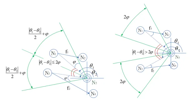
Flows can transmit data simultaneously if two flows do not interfere to each other. Here we define an interference-free condition; two flows can be scheduled in the same CTA if they satisfy the condition. A receiver only accepts signals in a certain beam direction, because it equips a directional antenna. We assume the reception and transmission beam widths are .
Let ( , ) and ( , ) be the senders and receivers of flow and . The interference-free condition is twofold:
(1) If (or ) is not located in ’s (or ’s) reception beam, (or ) cannot hear the signal from (or ) and two flows do not interfere with each other. (2) If (1) is not satisfied, but (or ) is not located in s (or s) sending beam,
then and still do not interference. Otherwise, and can not be scheduled in the same CTA.
The inter-piconet flow scheduled in a CTA has to verify the interference-free condition with all intra-piconet flow within the CTA. We use the symbol ∆ , to represent the angle between two vectors and , and according to the trigonometric function, ∆ , cos | || |· . For flows and , we can derive four angles, ∆ , , ∆ , , ∆ , , and ∆ , . In (4), if ’s transmission beam
15
does not cover or does not located in ’s reception beam, then is set to be 1. On the other hand, if and follow the condition, is set to be 1 in (5). Constraint (6) shows that flow i takes relay r in if (4) and (5) are satisfied. 4. Half-duplex constraint
We assume every DEV direct to a beam sector only, and apply the half-duplex constrain of the wireless communications to 60GHz WPAN. That is, more than two flows share the same DEV can not be scheduled in a CTA, which also means that a DEV can either be a sender or receiver of one flow in the same time duration. We derived the constraint as (7), where denotes the scheduled flow in .
5. CTAP extended by flow i
This constraint couples CTAP extension with scheduling result and this is also a key constraint that decides which relay and transmission timing combination. If an inter-piconet flow with relay r is allocated in , it may increase the time and also affect the accommodation to other flows. The CTAP extension is correlated to the CTA extension and new CTA allocation by scheduling each inter-piconet flow. In (8), if flow i is scheduled and the transmission time is larger than the CTA duration, the extension time is the differences of the two.
z Complexity
If there are m relay candidates, n inter-piconet flows, and t CTAs for intra-piconet flows, the complexity of finding the optimal solution is O( ! ). The computation includes ! scheduling orders, relay selection combination, and each flows has ( ) CTAs can be scheduled in. Obviously, the optimization is a NP problem, and the computation in a PNC would cause large power consumption.
16
Chapter 4. The Designed Joint Relay
Selection and Scheduling Algorithm
In this section, we introduce the designed algorithm in detail. We consider a WPAN which consists of multiple piconets, and intra-piconet and inter-piconet flows coexist in this network. The operations of nodes’ joining and leaving a piconet, PNCs’ announcements of their existence, axis alignment, and positioning are described in [5]. Nodes in this WPAN are classified into three types: PNC, relay-incapable, and relay-capable. The node which initiates a piconet acts as a PNC. Nodes which can receive beacons from at least two PNCs are relay-capable nodes. Nodes which are neither PNCs nor relay-capable are relay-incapable nodes.
Moreover, the “beam width” and “azimuth angle” represent the covered angle of the beam pattern, and the angle between the direction of the beam and the X-axis in azimuth plane, respectively. In our algorithm, we assume the transmission beam width and the reception beam width are ; the transmission azimuth angle and the reception azimuth angle of flow i are denoted as and , respectively. Moreover, let ∆ , be the included angle of two vectors and .
4.1 CTA-based relay selection
We first give five definitions and then explain how to select a relay for an inter-piconet flow in a specific CTA.
1. Interference-free
Refer to the interference constraint (4)-(6), two flows are interference-free if they can be scheduled in the same CTA. As shown in Fig.4.1, (the sender is , and the receiver is ) and (the sender is , and the receiver is ) are interference-free flows, while and (the sender is , and the receiver is )
17
interfere with each other (due to can hear the signals sent by ).
For flows and , we can derive four included angles ∆ , , ∆ , , ∆ , , and ∆ , . The condition that can transmit data simultaneously with
is neither can receive ’s signals nor can receive ‘s signals. Specifically, cannot receive ‘s signals only when (a) is not located within the reception beam of ; or (b) is not located within the transmission beam of . For condition (a), the induced angle ∆ , must be bigger or equal to half of
the reception beam width (i.e., ); otherwise, for condition (b), the induced angle ∆ , must be bigger or equal to half of the transmission beam width. Taking the effect of side lobes into consideration, we double the angle threshold to be . Similarly, in order not to receive ‘s signals, must be located outside the transmission beam of or must be located outside the reception beam of . Therefore, the induced angles ∆ , or ∆ , must be larger or equal to the
4 2 1 , N N N θ Δ 6 2 1 ,N N N θ Δ 4 2 3 ,N N N θ Δ 3 1 4 , N N N θ Δ 3 1 2 , N N N θ Δ 5 1 2 , N N N θ Δ 6 2 5 , N N N θ Δ 5 1 6 , N N N θ Δ Figure 4.1 Interference-free: an example
18
reception beam width and the transmission beam width, respectively. In short, the condition of interference-free is in (9).
∆ , || ∆ , , and
∆ , || ∆ , (9)
2. Concurrence restricted extent
For a relay-capable node in a specific CTA, the concurrence restricted extent is the area in angles which cannot be the reception azimuth angles of this node to avoid interfering with existing scheduled flows. Herein Θ, indicates the concurrence restricted extent of relay-capable node i in CTA j. Herein, Θ, , means that the reception azimuth angles of node i in CTA j cannot be any value between a and b;
, , indicates the union of two angle sets. We first use a
2-intra-piconet-flow case to explain how to derive Θ, , and then generalize our derivation.
In Fig. 4.2(a), there are two intra-piconet flows ( and ) and one inter-piconet flow. Since (the sender is and the receiver is ) and (the sender is and the receiver is ) are interference-free, both are scheduled in the same CTA, say CTA . We assume that is a considered relay of the inter-piconet flow, and and
are the azimuth angles of vectors and . It’s obvious that, if is not covered by the transmission beams of and or ’s reception beam does not cover and , the PNC can schedule these three flows in CTA . We consider two cases: the transmission beams of and overlap and do not overlap.
(a) The transmission beams of and overlap: the criterion that two beams overlap is |θ θ | 2φ (shown in Fig. 4.2(a)). The concurrence restricted extent of , which is colored green, is in (10).
19
Θ , | | , | | (10)
(b) The transmission beams of and do not overlap: Θ , , which is shown in Fig. 4.2(b), is simply in (11). In both situations, we block 2 to satisfy the interference-free condition.
, , (11)
Now we generalize our derivation by considering n intra-piconet flows allocated in CTA1. These n intra-piconet flows are sorted by the decreasing order of the azimuth
angle, and thus . Since transmission beams may or may not
overlap, we further assume that these n beam patterns are grouped into m beam sets, where . The ith beam set consists of ni overlapped transmission beams, and
thus ∑ . The generalization form of Θ , is in (12).
Θ , | | φ φ …
φ (12)
3. Set of relay candidates
1 θ 2 θ ϕ ϕ ϕ θ θ + − 2 2 1 ϕ θ θ + − 2 2 1 ϕ θ θ1− 2 ≤2 ϕ 2 1 θ 2 θ ϕ θ θ1− 2 >2 ϕ 2 (a) Overlapped transmission beams (b) Non-overlapped transmission beams
20
Considering allocating inter-piconet flow i in CTA j, all qualified relay-capable nodes form the set of relay candidates, which is denoted as , . To be a relay-candidate node, the reception azimuth angle of a relay-capable node is not in the concurrence restricted extent, and the transmission azimuth angle does not interfere with any receiver of the scheduled intra-piconet flows.
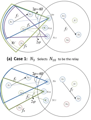
An example is shown in Fig. 4.3(a). In this example, two piconets form a WPAN. In this network, there are 11 nodes, two intra-piconet flows ( from to ; from to ), and two inter-piconet flows ( from to ; from to
). , , and are three relay-capable nodes. The transmission and reception beam widths are 30°. We assume the PNC of piconet 1 schedules in CTA . For , the concurrence restricted extent of is the blue sector. Since the blue sector covers , is not qualified to be a relay candidate of . Moreover, since the transmission beams of and do not cover ( , ) and ,
21 4. Concurrence index
Each relay candidate is assigned a concurrence index and this index is exactly utilized to select a relay for an inter-piconet flow. Assume that there are m relay candidates for an inter-piconet flow in CTAj. The concurrence index of relay
candidate k is calculated as in (13).
∑ , , , 1,2, … , (13)
5. CTA-based relay designation
For each inter-piconet flow in a specific CTA, the PNC designate the node which has the largest concurrence index among all relay candidates to be the relay.
We use Fig. 4.3 again to illustrate how to select a relay. If selects as its relay node, the concurrence restricted extent of is 90° (i.e., 3φ, the green sector in Fig. 4.3(a)), while it is 60° for (i.e., 2φ, the purple sector in Fig. 4.3(a)).
o 60 2ϕ= ϕ 2 o 30
(a) Case 1: selects to be the relay
o 60 2ϕ= ϕ 2
(b) Case 2: selects to be the relay
22
Therefore, ° 0.792. On the other hand, if selects as its relay, the concurrence restricted extent of and is 90° (shown in Fig. 4.3(b)).
Therefore, ° 0.833. Since , the selected relay for in
CTA is .
4.2 Scheduling Algorithm
Our scheduling algorithm consists of two phases: the first phase is to allocate channel time to intra-piconet flows, while the second phase is to serve inter-piconet flows. For each piconet, the PNC performs phases 1 and 2 operations in order.
1. Phase 1: intra-piconet flow scheduling
The PNC first sorts all intra-piconet flows and the last hop of the inter-piconet flows in decreasing order of the required channel time. The flow which has the longest required channel time among all will be scheduled first. A new intra-piconet flow can be allocated in a CTA if it is interference-free with all existing flows. When none of existing CTAs can accommodate this new intra-piconet flow, the PNC allocate a new CTA to the flow. The detailed operations are in [6].
After performing phase 1 scheduling operations, we assume that all intra-piconet flows utilize n CTAs for data delivery. Let be the time duration of the ith CTA.
From [6], we know .
2. Phase 2: inter-piconet flow scheduling
After serving all intra-piconet flows, the PNC then starts to schedule inter-piconet flows. Similarly, all inter-piconet flows are sorted in decreasing order of the requested channel time, and the inter-piconet flow which has the longest requested channel time will be scheduled first.
23
the sorted flows, and their requested channel times are , , … , , and .
Briefly speaking, for each inter-piconet flow , the PNC first searches all CTAs in order to find the possibility of allocating in existing CTA by performing the interference-free verification, and concurrence-restricted extent derivation. When discovering a CTA which has non-empty set of relay candidates, the scheduling for completes. The detail steps are summarized in the following and the pseudo code is shown in Fig.4.4
Step 1:
For , the PNC performs the verification of interference free, derives Θ , and , . If , , then the PNC derives Θ , and , . This process keeps till the PNC discovers a non-empty , , 1 or the PNC has verified all n CTAs.
Step 2:
If discovering a non-empty , , 1 , the PNC allocates in CTA , calculates the concurrence index of each relay candidate, and designates the one with the largest index value as the relay node. The calculation is introduced in Sec. 4.1. Besides, the PNC sets the CTA time duration to be max , and re-sort this CTA to keep CTAs in decreasing time order.
Step 3:
If none of CTAs can accommodate (i.e., , , ), the PNC allocates a new CTA (i.e., CTA ) to , sets , re-sorts CTAs, and updates the number of CTAs to be (n+1).
Step 4:
The PNC treats the scheduled inter-piconet flow as an intra-piconet flow.
24
The PNC keeps performing steps 1-4 on , , … , .
We use the example in Fig. 4.3 again to illustrate the operations of the designed joint algorithm. In Fig. 4.3, the required transmission times of , , , and are 0.7 ms, 0.5 ms, 0.6 ms, and 0.3 ms, respectively. After phase 1 scheduling, the PNC of piconet 1 allocates CTA to and sets be 0.7 ms; the PNC of piconet 2 also allocates its CTA to and sets be 0.7 ms, as shown in Fig. 4.5. The PNC of piconet 1 then performs phase 2 operations to schedule and . Since , the PNC schedules first. As we previously described, and are two relay candidates of and , thus acts as the relay node of . The PNC allocates in CTA without modifying the CTA time. Now is viewed as an intra-piconet flow of piconet 1, and the PNC re-checks the concurrence restricted extent and the set of relay candidates for . Since is not in the green and the blue sectors, and is interference-free with and , it can be scheduled in CTA , and its relay candidates are and . The concurrent restricted extent of and is (60° 30° 20° 110°) and (60° 30° 10° 100°), respectively. The
concurrence index of is ° 0.722, while it’s ° 0.694 for
. Therefore, the PNC designates to be the relay of .
To schedule the second hop of and , the PNC of piconet 2 can only allocate CTA to , and thus 0.5 ms. Similarly, the PNC performs phase 2 operations on and discovers that can be allocated in CTA without interfering with . The scheduling result is summarized in Fig. 4.5.
25
Phase 1:
Schedule intra-piconet flows and the last hop of inter-piconet flows using algorithm in [6]
Phase 2:
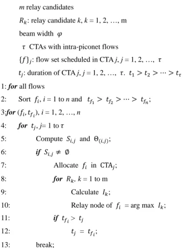
Joint relay selection and scheduling algorithm
Input: n inter-piconet flows
( , ): flow ID and request channel time, i = 1, 2, …, n m relay candidates
: relay candidate k, k = 1, 2, …, m beam width
CTAs with intra-piconet flows
: flow set scheduled in CTA j, j = 1, 2, …, : duration of CTA j, j = 1, 2, …, .
1: for all flows
2: Sort , i = 1 to n and ; 3:for ( , ), i = 1, 2, …, n 4: for , j= 1 to 5: Compute , and Θ , ; 6: if , 7: Allocate in CTA ; 8: for , k = 1 to m 9: Calculate ;
10: Relay node of = arg max ; 11: if >
12: = ;
13: break;
14:// If the inter-piconet flow can not be scheduled in the exist CTAs, PNC will allocate one new CTA for that flow
15: if CTA , 16: 1; 17: Allocate in CTA ; 18: ; 19: for , k = 1 to m 20: Calculate ;
21: Relay node of = arg max ;
22: : ; //Treat the scheduled flow as an intra-piconet flow
26 z Complexity
The complexity of the joint algorithm is O( ). Compare to the optimal solution, the joint algorithm can greatly decrease the complexity and the computation time. Although the scheduling result is not the best assignment, the differences are quite small and we show the comparison of utilized channel time in the simulation part.
Piconet 1 Piconet 2
CTA1 CTA1 CTA2
(f2, 0.6 ms) (f1, 0.7 ms) (f4, 0.3 ms) (f3, 0.5 ms) (f3, 0.5 ms) (f4, 0.3 ms) t1=0.6 ms, t2=0.5 ms t1=0.7 ms Phase 1 scheduling results Phase 2 scheduling results Figure 4.5 The scheduling results of the example in Fig. 4.3
27
Chapter 5. Performance Evaluation
In this section, we evaluate the proposed scheduling algorithm by developing simulation experiments. We first describe our simulation environment, performance metrics, and the discussion results.
5.1 Simulation environment
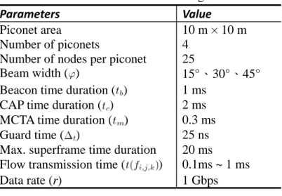
Here we compare the performance of the designed joint relay selection and scheduling algorithm with CTAP-minimized scheduling [6] with randomly selecting relay nodes for inter-piconet flows. In particular, we investigate two variations of CTAP-minimized scheduling algorithm: randomly selecting one relay for all inter-piconet flows (denoted as 1 relay + CTAP_minimized), and randomly selecting one relay for each inter-piconet flow (multiple relay + CTAP_minimized). In our simulation, we consider a 4-piconet chain topology, and each piconet has 25 nodes. Parameter settings in the following experiments are listed in Table 5.1. Refer to [15], we set the CAP time duration to 2 ms to gain our throughput. Each simulation result is the average of 30 runs. Utilized channel time (T), system throughput ( ) and spatial-directional reuse degree ( ) are three observed and discussed performance
Table 5.1 Parameter settings
Parameters Value
Piconet area 10 m × 10 m
Number of piconets
Number of nodes per piconet
4 25
Beam width ( ) 15°、30°、45°
Beacon time duration ( ) 1 ms
CAP time duration ( ) 2 ms
MCTA time duration ( ) 0.3 ms
Guard time ( ) 25 ns
Max. superframe time duration 20 ms
Flow transmission time ( ) 0.1ms ~ 1 ms
28 metrics. Their definitions are in the following.
1. Utilized channel time (T): the utilized channel time to schedule all flows, and it is calculated as
3∆ ∑ ∑ , ∆ ,
where is the number of consumed superframes; , , , and ∆ are the time duration of a beacon, CAP, MCTA, and interframe guard time, respectively.
and , are the number of CTAs in the ith superframe, and the jth CTA time duration of the ith frame, respectively.
2. System throughput ( ): the aggregated transmission rate of the considered WPAN and its unit is Gbps upon all nodes operating at the same transmission data rate r Gbps, then the system throughput is
∑ ∑ ∑ , , ,
,
where , and , , are the number of flows which are scheduled in the jth CTA of the ith superframe, and the channel time requirement of the kth flow in the
jth CTA of the ith superframe.
3. Spatial channel reuse degree ( ): the number of scheduled data flows per data transmission time unit (ms), and its definition is
∑ ∑ ,
, ,
5.2 Simulation Result
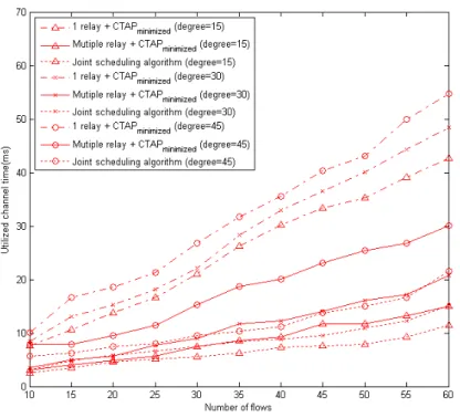
The performance of consumed channel time upon varying the number of flows and 15°, 30°, and 45° is shown in Fig. 5.1. In general, the designed joint relay selection and scheduling algorithm performs better than CTAP-minimized scheduling algorithm. Moreover, 1 relay performs the worst among all due to it only uses one relay node. Inter-piconet flows wait for the relay to be served in turn. As the beam width increases, the performance gap between the two algorithms also increases. Specifically, compared with CTAP-minimized with random relays, our algorithm achieves 22.2% performance improvement when setting 15° , and this
29
improvement further increases to 31.1% and 37.6% when setting 30° and 45°. The reason is that, when the beam width is small, the interfered areas of transmission and reception beams are small, thus even randomly designating a relay node to serve an inter-piconet flow, the PNC can find a suitable CTA to schedule this flow without interfering with existing intra-piconet flows. On the other hand, when the beam width becomes 30° or 45°, the probability that none of CTAs can accommodate this inter-piconet flow is high. In such a situation, the PNC allocate a new CTA for this inter-piconet flow, and thus the total utilized channel time increases.
The performance of system throughput is in Fig. 5.2. As we expected, our algorithm performs the best among three approaches. This demonstrates that the metric of concurrence index provides efficient interference avoidance.
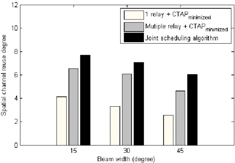
The performance of scheduling efficiency is shown in Fig.5.3. Generally speaking, as the beam width increases, the reuse degrees of three approaches diminish. In particular, the degradation of CTAP-minimized scheduling with one relay node is the least among three approaches. The reason is that the reuse degree is mainly limited by the relay node, not the beam width and the concurrence restricted extent. Contrarily, compared with our joint algorithm, the reuse degree of CTAP-minimized with multiple relays is affected by the positions of selected relays. The factor of random relay selection results in at most 23.71% ((6.03-4.60)/6.03=23.71%) performance difference.
In Fig. 5.4, we compare the performance of our algorithm and the optimized result. Since the optimization problem is a NP problem, we can use the brute-force method to try on every feasible solution. Limited by the simulation time, we simplify the environment to 2 piconets and the maximum flows to 30 flows, and other parameters are the same. The result shows that the differences grows largest while the beam
30
width is 45∘. It is because a not suitable relay selection of a flow will block more concurrent restricted extent and let more inter-piconet flow scheduled in a new CTA. The degradations of our heuristic algorithm are 10.63%, 15.02%, and 23.02% while the beam width are 15∘, 30∘, and 45∘, respectively.
31
Figure 5.2 The system throughput v.s. the number of flows upon 30° and r = 1 Figure5.1 The utilized channel time v.s. the number of data flows
32
Figure 5.2 The utilized channel time v.s. the number of data flows (Optimized
v.s. Heuristic)
33
Chapter 6. Conclusions and Future Work
In this paper, we explained the necessity of inter-piconet communications in a WPAN. Inter-piconet communications can be realized by utilizing relays. We further showed that relay selection impacts on the system performance. Based on our observation, we designed a joint relay selection and scheduling algorithm which can deal with both intra-piconet and inter-piconet flows. The joint algorithm consists of two phases: the first phase is to schedule intra-piconet flows; the second phase is to schedule inter-piconet flows. Relay candidates are screened through the verification of “interference-free” and the derivation of “concurrence-restricted extent”. When multiple relay candidates are available, “concurrence index” is used to designate the most suitable relay.We conducted simulations to evaluate the performance of our algorithm. The simulation results showed that, compared with CTAP-minimized with randomly multiple relays scheduling algorithm, our algorithm achieves 20%-40% improvement in utilized channel time, system throughput, and spatial channel reuse degree.
We design an algorithm including the relay selection and inter-piconet flows scheduling to minimize the CTAP extension and improve the system throughput in IEEE 802.15.3c networks. The flows we consider here need better QoS. They request sufficient resource, and PNC guarantees different CTA duration to serve those flows. However, in practical, the 802.15.3c networks are also applied to real-time transmission. In this application, the flows requests are usually best effort. We have to design an algorithm which considers the service type of saturated flow request or real-time flow request. We assume the CTAP duration and the number of time slot in CTAP are fixed, and our goal is to divide the CTAP into several CTAs with the same duration and group all requested flows (intra- and inter-piconet flows) to concurrently
34
transmit in those CTAs. Our challenge is how to decide the bottleneck piconet in which each flow can obtain the less resource and limit the inter-piconet flows’ transmission. The relay selection is important because the best relay selection can let most flows without interference transmit simultaneously. If less groups share a superframe, the groups can get more resource. The basic design concept is to maximize the group members and minimize the group number. In general, the protocol components must contain the relay selection scheme, grouping algorithm, and bottleneck piconet detection.
35
References
[1] "IEEE Standard for Information technology - Telecommunications and information exchange between systems - Local and metropolitan area networks - Specific requirements Part 15.3: Wireless Medium Access Control (MAC) and Physical Layer (PHY) Specifications for High Rate Wireless Personal Area Networks (WPANs) Amendment 1: MAC Sublayer," IEEE Std 802.15.3b-2005 (Amendment to IEEE Std 802.15.3-2003), pp. 0_1-146, 2006.
[2] "IEEE Draft Amendment to IEEE Standard for Information technology--telecommunications and information exchange between systems--Local and metropolitan area networks--Specific requirements--Part 15.3: Wireless Medium Access Control (MAC) and Physical Layer (PHY) Specifications for High Rate Wireless Personal Area Networks (WPANs): Amendment 2: Millimeter-wave based Alternative Physical Layer Extension," IEEE Unapproved Draft Std P802.15.3c/D08, March 2009
[3] IEEE 802.11 WLAN Very High Throughput in 60 GHz Task Group ad (TGad), http://www.ieee802.org/11/, Online Link.
[4] F. daCosta, Dynamic Beacon Alignment in Simultaneously Operating Piconets (SOP) Using the Heart Beat Approach, IEEE Std. P802.15- 04/135r0, March 2004.
[5] Ming-Pei Hsu and His-Lu Chao, "Scheduling with Reusability Improvement for Millimeter Wave Based Wireless Personal Area Networks," Communications
(ICC), 2010 IEEE International Conference on, vol., no., pp.1-5, 23-27 May 2010
[6] Hsi-Lu Chao and Ming-Pei Hsu, “CTAP-Minimized Scheduling algorithm for Millimeter Wave Based Wireless Personal Area Networks,” accepted by
36
[7] J.Y. Wang, Z. Lan, et.al., “Robust and highly efficient beamforming procedures for 60GHz WPAN,” IEEE 802.15-08-0190-003c, November 2008.
[8] Peng Xue, Peng Gong, Duk Kyung Kim, "Enhanced IEEE 802.15.3 MAC Protocol for Efficient Support of Multiple Simultaneously Operating Piconets,"
Vehicular Technology, IEEE Transactions on, vol.57, no.4, pp.2548-2559, July
2008
[9] L. X. Cai., Lin Cai, Xuemin Shen, and J. W. Mark, “Efficient Resource Management for mmWave WPANs,” Wireless Communications and Networking
Conference, 2007. WCNC 2007. IEEE, vol., no., pp.3816-3821, 11-15 March
2007
[10] L. X. Cai, Lin Cai, Xuemin Shen, and Mark J. W., ”REX: A andomized ErXclusive region based scheduling scheme for mmWave WPANs with directional antenna,” Wireless Communications, IEEE Transactions on, vol.9, no.1, pp.113-121, January 2010
[11] Zhou Lan, Chin-Sean Sum, Junyi Wang, Baykas T., Kojima F., Nakase H., Harada H., “Relay with Deflection Routing for Effective Throughput Improvement in Gbps Millimeter-wave WPAN Systems,” Selected Areas in
Communications, IEEE Journal on, Vol. 27, no.8, pp.1453-1465, October 2009
[12] Zhou Lan, Junyi Wang, Jing Gao, Chin-Sean Sum, Fumihide Kojima, Tuncer Baykas, Hiroshi Harada, Shuzo Kato, “Directional Relay with Spatial Time Slot Scheduling for mmWave WPAN Systems,” Vehicular Technology Conference,
2010. VTC Spring 2010. IEEE, vol., no., pp.1-5, 16-19 May 2010
[13] Chin-Sean Sum, Zhou Lan, Ryuhei Funada, Junyi Wang, Tuncer Baykas, Mohammad Azizur Rahman, and Hiroshi Harada, “Virtual Time-Slot Allocation Scheme for Throughput Enhancement in a Millimeter-Wave Multi-Gbps WPAN
37
System,” Selected Areas in Communications, IEEE Journal on, Vol. 27, no.8,
pp.1379-1389, October 2009
[14] Hang Su and Xi Zhang, “Joint Link Scheduling and Routing for Directional-Antenna Based 60 GHz Wireless Mesh Networks,” Global Telecommunications Conference, 2009. IEEE GLOBECOM’09, Vol., no., pp.1-6,
30 November 4 December 2009
[15] Chang Woo Pyo and Hiroshi Harada, “Throughput analysis and improvement of hybrid multiple access in IEEE 802.15.3c mm-wave WPAN,” Selected Areas in