ROBUST ADAPTIVE ARRAY BEAMFORMING IN TWO DIMENSIONS
Ju-Hong Lee and Jeng-Hong Chen
Department of Electrical Engineering National Taiwan University
Taipei, Taiwan, R.O.C.
Al~S'l'ltAC'f
:I11 cffc~ctive t,echnique for robust adaptive beamforming iisi itg oiic-tlime~isioi~al ( 1-D) linear array has been proposed
1)y o i i v of the aiitliors i n [I]. It was shown that the resulting
l ) ( ~ ; t i i t l o i ~ i i i i ~ r c a . ~ cur(' the difficulties of using conventional i~ol~iist, tc~~liiiiqiics. I n this paper, we investigate the extension
0 1 1 Iiv iil)ovc> t,ec.liniqiie to two dimensions (2-D j . We present I,wo iilgorithnis for the iinpleineiitation of the 2-D robust t , ( ~ l i I i i q r r c , . l'hc coil1 par ison based on computational complexity is i i i a . t l c ~ . (lomputer simulations are given for illustration.
1. IN'I'I1OllUCTION
Atliipt,ivc array beanifornier designed for receiving the tlosii,cd sigiial i n specified beam direction while rejecting noise itmd o ~ l i ~ i , directional jaiiiniers is widely used in radar, sonar, iili(l iiii\,lly c.omni~iiiicatioii systems. However, its performance is v c ~ y scwsit.ivc to the accuracies of signal and array situations 1)oc~itiis~ a i l optiiiiuni adaptive beaniforiner is designed under
t,h, iissiiiitptions of ideal signal characteristics and exact array c,oiil'igura.t,ioiis. It has been shown that the effectiveness of an ii,(Iiip~,i vc 1)eatiiforiner can be destroyed even if a small
I t i i s i I iiit,(,l t ariscs iit practical circumstances.
Miiiiy t,c.chniqucs have been presented to tackle the
~ l o , q i ~ i ~ ~ l i i . t ~ ~ i t eff'eci, due to steering errors [2-Y]. These
c,oiivc~iit.ioiiaI nietliods are based on either imposing directional
d(~riviit,iv(~ constraints t,o allow direct control of array sc'iisil ivi1,y or rcducing the sensitivit,y of array performance to riiig orrors. However, the dmwback is that t,he abilities
01' c~liiiiinating wise and interference are inevitably (Ic~t,~~i~iortt tcd. I~eceiitly. one of the authors has proposed an (~I'I(TI ivv approa.ch for robust adaptive beamforming in [I] to (Icvil witli the case of using 1-D linear array. In practice, it is l)ossil)Icx 1,1~it,1, there exists more than one signal coming from
d i l l c w i i l directions but having the same angle with respect to
t,Iiv I)roa.tlsitle ol a 1-1) linear array. In this circumstances, the
I--D array cannot distinguish these different signals. Hence, 2-D arrays are required for the purpose of beamforming. In this paper, We extend the technique of [l] to two dimensions . It is shown that the resulting 2-D adaptive array beaiiiformer is robust, in the presence of steering errors.
11. T H E 2-D ROBUST ADAPTIVE BEAMFORMING The 2-1) array is assumed to be rectangular with size M x N and the array sensors are equally spaced with interelement spacings along the X and Y axes are d, and d,, respectively. Its configuration is shown in Figure 1. The directional angles of the j-th jammer and the signal are denoted by (dk,@,J,k=1,2, ..., K and (B,,@,), respectively. The input of the mn-th array sensor, which is located at the intersection of the in-th row and the n-th column, is given as
where @,(ti and a.(t) denotes the complex envelopes of the desired signal and the j-th jammer, respectively, k, the wavenumber, and u,=sinS,cos@,, v,=sinB,sin@,, uj=sin6'jcos@j
,
vj=siiiBjsin@j, and n,,,(t) is the complex noise of mn-th sensor. Using ( 1 j, the input signal vector of the m-th row of the 2-D array, which is of size N x l , is given asJ T L!mn(t)=[ uml(t)> . . . I um,(t)
1
K (2) - -'ps(t)%m+
jzl
oj(t)!jm+
nm(t)\vhere
sSlll
is the signal phase vector at the ni-th row.!j,,, is the phase vector of the j-th jammer, and G(t) is the noise vector. The input vector of the
2-D
rectangular array can be defined as the MNxl vector given bywhere
ss
is the phase vector of the desired signal( 5 )
and n(t) is the noise vector. Then the covariance matrix is given as
where
t
denotes the conjugate transposition and E the expect a t ion.Consider the m-th row of the 2-D MxN array. Assume that the tolerance error of the steering error, which is given as
zdm
with steering angle ( I , @ ) , due to the mismatch is smaller than the distance between steering and jammer phase vectors. Based on the fact that the output signal-to-noise ratio ( S N l t ) of an optimized adaptive beamformer becomes maximum when the steering vector concides with the signal pha,se vector, we first find the optimum weight vectorEAm
for a given steering vector by minimizing the array output power with main beam constraint. After obtaining the,
we adjust the steering vector in a prescribed class S, of possible arrival phase vectors of the signal. This procedure is repeated until the outputSNK
of the optimized adaptive beamformer reaches a maximum. Therefore, the resulting optimization problem can be written as [I1Maximize{ M n i m i z e
E((&
&,,(t)(’) ?dmEs,
!&dmX1Subject to Isdmi/ = 1 , for i=1,2 ,...,
N
(7) whereS,
E {sdml 11
sdm-s,
11’
5 6 }, 6
is the tolerance error for robustness. Therefore, we correct the steering vector error by iteratively adjusting the steering vector during the optimization process. The adaptive algorithm presented in [l] for 1-D robust adaptive beamforming can be employed to search the correct steering vectorsm
. Then the corresponding optimum weight vector is given as [lo]for ni=1,2, .M, where R,,,zE&(t)L-’(t)] .Finally, all of the
hl resulting 1-D optimum weight vectors are used to form an
MNxl array weight vector
Eo
which is given asand then obtain the associated
2-D
array beam pattern. An alternative approach is to only save the corrected steering vectorsm
after the 1-D robust processing. Then all of the M corrected steering vectors are used to form an MNxl steering vector as in (5). Then we compute the corresponding M K x l array weight vectorEo
wliich is given asComparing the computational complexity. we note from ( S ) and ( 1 0 ) that the second algorithm faces tlie problem of computing the inverse of R with size MNxR/II”J in (10). This leads to heavy computational burden. By contrast, using the first algorithm requires the coniputation of inverse of Rum with size N x N ouly i n ( S ) . In the nest section. we thus on1~- present tlie simulation examples based OII the first algorithm.
1II.SIMULATION EXAMPLES
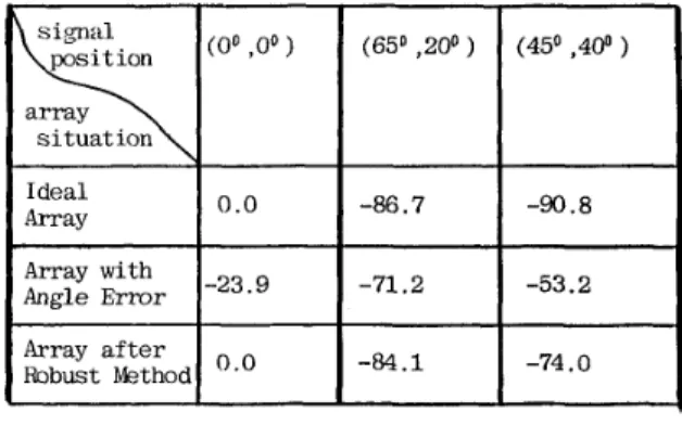
In this section, several computer simulations are presented for illustration. We consider a 7x7 2-D rectangular array. Both the interelement spacings d, and d,. are set to be half-wavelength ( A / ? ) . The desired signal is at ( US.@,)=(0”,0”) while two incoherent jammers are located at (U1,@1)=(650,20”) and ( U2,@,)=(450,400), respectively. The noise received at the array sensors is assumed to be spatially white with SNR=2O dB and JNR (jammer-to-noise ratio) = 10 dB.
A. Example of Steering Angle Mismatch.
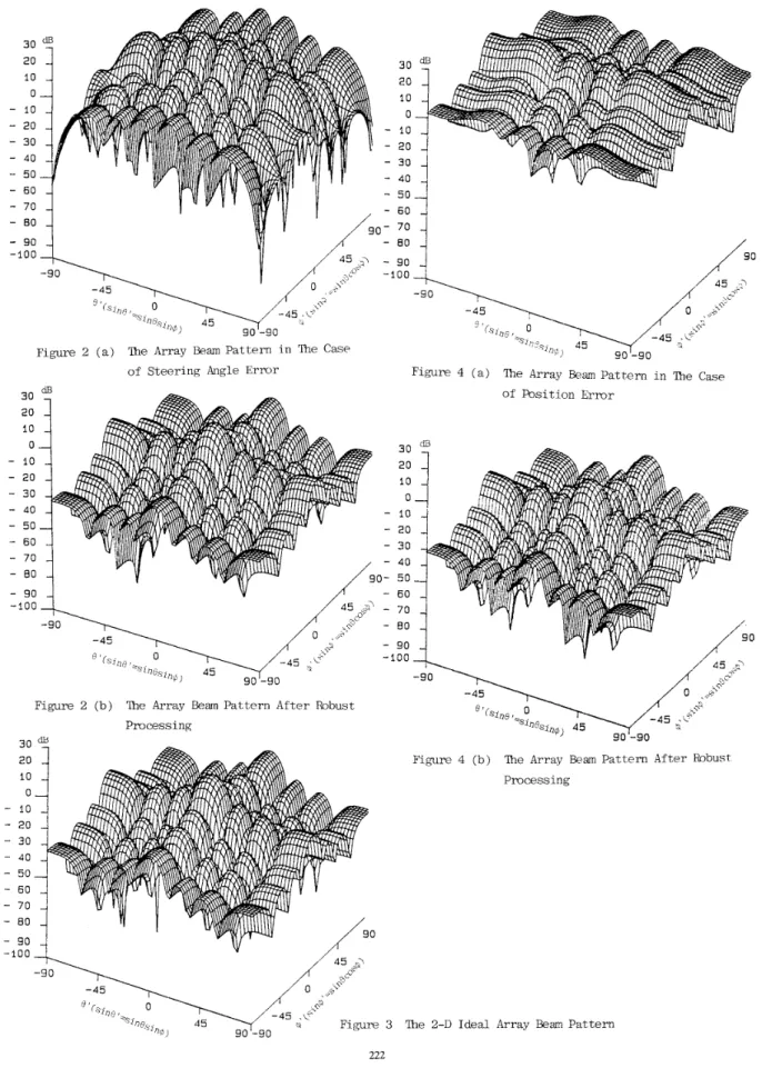
In this case,the steering angle error is (A0,A$)=(0.5°,0..50). Figure 2 shows the 2-D array beam patterns under the steering angle error and using the proposed robust technique after 500 iterations, respectively. The ideal result for this case is shown in Figure 3 . Table 1 lists the array gains for this case. Comparing these results, we note that the proposed robust technique can effectively cure the 2-D array performance degradation due t o steering angle error. Moreover, the beam pattern using the robust technique is as good as the ideal beam pat tern.
13. Kxample of Sensor Position Error
I n this case, we assume that the steering vector error is only
due to 2-U random perturbation in sensor positions. The raiitloni position errors are Gaussian with mean = 0 and variiuice = 0.15 half-wavelength in each dimension. Figure 4 sliows t l i e resulting 2-D array beam pattern when the 2-D array snlfers the 2-D random perturbation and the resulting 2-L) a.rray beam pattern using the proposed robust approach after 500 iterations, respectively. Table 2 lists the array gains
l o r tliis case. Again, we note from these results that the
proposcd robust technique demonstrates its effectiveness in tlttaliiig with tlie degradation effect due to sensor position iiiisiiia,t,(,li aiid provides a 2-D beam pattern as good as that of t , I i v i d ~ 1 one shown i n Figure 3.
.]U-Ilong Lee and Jeng-Fu Wu, ' I A Novel Approach for Robust Adaptive Beamforming ' I , in Proc. of IEEE Int. Conf. on ASSP, Glasgow, UK, May 1989, pp. 2740-2743.
F. Habor, Y. Bar-Ness, and C.C. Yeh, I ' An Adaptive Interference Canceling Array Utilizing Hybrid Techniques 'I IEEE Trans. AES, Vol AES-19, No.5, pp.795-803, Sept. 1983.
R.T. Compton, Jr. I ' The Effect of Random Steering Vect,or Errors i n the Applebaum Adaptive Array I ' , IEEI: Trans. AES, Vol AES-18, No.5, pp.392400, Sept. 1952.
1t.T. Compton, Jr. 'I Pointing Accuracy and Dynamic ltange in a Steered Beam Adaptive Array 'I, IEEE ' ~ r a n s . Vol. AES-16, No.3,pp. 280-287, May 1980. L.C. Codara, ' I Error Analysis of the Optimal Antenna A1ra.y Processors (I, IEEE Tran. AES, Vol. AES-22, N o . 4 , pp. 3 9 5 4 0 9 , July 1986.
N . l i . Jablon, I ' Adaptive Beamforming with the Generalized Sidelobe Canceller in the Presence of Array Imperfections ' I , IEEE Trans. AP,Vol. AP-34, pp.
M.H. Er and A. Cantoni, I' Derivative Constraints for Broadband Element Space Antenna Array Processors 'I, IEEE Trans. ASSP, Vol. ASSP-31, No.6, pp. 1375-1393, Dec. 1983.
L.M. Buckley and L.J. Griffths, ' I An Adaptive Generalized Sidelobe Canceller with Derivative Constraints ' I , IEEE Trans. AP, Vol. AP-34, No.3, pp. 3114319, Mar. 1986.
I<. Takao and
N.
Kikuma, "Tamed Adaptive Antenna Array 'I, IEEE Trans. AES, Vol. AES-34, No.2, pp.388-394, Mar. 1986.996-1012, Aug. 1986.
[lo] R.A. Monzingo and T.W. Miller, INTRODUCTION T O ADAPTIVE ARRAYS, New York : Wiley, 1980.
2 4 Icth Sourcc
I I
I
1 ' -
f
N,Figure 1 The 2-D MxN Rectangular Array
Table 1 Array Gains
(a)
for the Case of SteeringAngle E r r o r
Table 2 Array Gains (dB) for the Case Of Position
E r r o r
Array 10.0
Figure 2 ( b ) The Array Beam P a t t e r n A f t e r Robust Processing
of P o s i t i o n E r r o r
- - 1
Figure 4 ( b ) lhe Array Beam P a t t e r n A f t e r Robust Processing
3 The 2-D Ideal Array Beam P a t t e r n