Intermetallic Reactions in Sn-8Zn-20In Solder Ball Grid Array
Packages with Au/Ni/Cu and Ag/Cu Pads
YU-CHIH LIU,1WEI-HONG LIN,1HSIU-JEN LIN,1 and
TUNG-HAN CHUANG1,2
1.—Institute of Materials Science and Engineering, National Taiwan University, Taipei 106, Tai-wan. 2.—E-mail: [email protected]
During the reflow process of Sn-8Zn-20In solder joints in the ball grid array (BGA) packages with Au/Ni/Cu and Ag/Cu pads, the Au and Ag thin films react with liquid solder to form #3-AuZn4/#-Au7Zn18 and $-AgZn6 intermetallics, respectively. The #3/# intermetallic layer is prone to floating away from the solder/Ni interface, and the appearance of any interfacial intermetallics cannot be observed in the Au/Ni surface finished Sn-8Zn-20In packages during fur-ther aging treatments at 75°C and 115°C. In contrast, $-CuZn5/#-Cu5Zn8 in-termetallics are formed at the aged Sn-8Zn-20In/Cu interface of the immersion Ag BGA packages. Bonding strengths of 3.8N and 4.0N are found in the re-flowed Sn-8Zn-20In solder joints with Au/Ni/Cu and Ag/Cu pads, respectively. Aging at 75°C and 115°C gives slight increases of ball shear strength for both cases.
Key words: Sn-8Zn-20In solder, intermetallic compounds, Au/Ni/Cu pad,
Ag/Cu pad, ball shear strength
INTRODUCTION
Au/Ni metallization has been widely used for sur-face finishing of printed circuit boards.1The Au thin film can protect Cu pads from oxidation and promote the wettability of liquid solder during the reflow pro-cess. However, the Au/Ni surface finishing process is quite costly and complex. In addition, the Au film is apt to react with Sn-based solders to form AuSn4 intermetallic compounds, leading to the embrittle-ment of the solder joints. Immersion silver is a vi-able alternative for the surface finishing of Cu pads. It cannot only provide immunity against Au em-brittlement but also provide the advantages of lower cost and simpler operation.
Among a number of Pb-free solders, the Sn-Zn sys-tem possesses the merits of adequate melting sys- tem-perature, low cost, high strength, and longer fatigue life.2 However, the eutectic Sn-9Zn solder exhibits insufficient wettability and oxidation resistance. The addition of indium into solder alloys can im-prove the wettability and lower the melting point as well. The solidus temperatures of Sn9Zn10In and Sn9Zn50In alloys, as reported by McCormack and
Jin, are 178°C and 188°C, respectively, both lower than the melting points of eutectic Sn9Zn (199°C).3,4 Further investigations on the phase equilibria and thermodynamics properties of In and Sn-Zn-In-Bi have been conducted by Cui et al.5and Yoon et al.6This present study is concerned with the inter-facial reactions of a Sn-8Zn-20In solder with Au/Ni/ Cu and Ag/Cu pads in ball grid array (BGA) pack-ages.
During the soldering reaction, the formation of in-termetallic compounds that takes place at the inter-face allows for sound wetting and bonding. However, an overgrowth of interfacial intermetallics will cause embrittlement and cracking in the solder joints. During the reflow process of Sn-8Zn-20In sol-der BGA packages with Au/Ni and Ag surface fin-ishes, the Au and Ag thin films dissolve rapidly into the molten solder matrix, resulting in interfa-cial reactions of liquid Sn-8Zn-20In with solid Ni and Cu in the Au/Ni/Cu and Ag/Cu pad struc-tures, respectively. As indicated in published re-search, the intermetallic compounds formed during the Sn9Zn/Ni and Sn9Zn/Cu soldering reactions are Ni19.0Zn80.0Sn1.0andCu33.4Zn66.5Sn1.0, respectively.7 Yoon et al. showed that a Cu5Zn8 intermetallic phase appeared at the interfaces between liquid Sn-(Received May 9, 2005; accepted August 30, 2005)
Zn-In-Bi solders and Cu substrates at the heating temperature of 240°C,6 while Shiue et al. aged a Sn9Zn15In solder joint on a Au/Ni-P deposited Cu substrate at 90°C for 168 h and reported an inter-metallic compound of Zn-rich # phase (NiZn3) at the interface.8In the present study, a Cu
5Zn8 interme-tallic compound appears in the immersion Ag sur-face-finished Sn-8Zn-20In BGA package. However, no trace of the NiZn3 intermetallic, as reported by Shiue et al., is found in the Sn-8Zn-20In solder joints of BGA packages with Au/Ni/Cu pads.
EXPERIMENTAL PROCEDURES
For this study of interfacial reactions, Sn-8Zn-20In (wt.%) solder balls of 0.4-mm diameter were dipped in rosin mildly activated (RMA) flux, placed on the Au/Ni/Cu and Ag/Cu pads of various BGA packages, and reflowed in a hot-air furnace equipped with five heating zones. The reflow perature profile is shown in Fig. 1; the soaking tem-perature and peak temtem-perature were fixed at 169°C and 210°C, respectively. After reflow, a separate set of these specimens was further aged at 75°C and 115°C for durations varying from 100 to 1000 h.
The reflowed and aged specimens were cross-sectioned through a row of solder balls, ground with 1500 grit SiC paper, and polished with 0.3%m Al2O3 powder. The morphology of intermetallic compounds formed in the solder joints was observed using a scanning electron microscope (SEM), and their chemical compositions were analyzed with energy-dispersive x-ray spectrometry (EDX). The bonding strengths of the Sn-8Zn-20In solder joints under various conditions were measured via ball shear testing. The measurements were taken at a shear rate of 0.1 mm/s and a shear height of 80 %m (about 1/4 of the reflowed ball height). The fractography of the solder joints after ball shear tests was examined by SEM.
RESULTS AND DISCUSSION
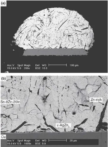
The microstructure of the as-cast Sn-8Zn-20In sol-der is shown in Fig. 2. A large amount of needle-shape Zn-rich precipitates (shown in black) are seen embedded in the "-Sn matrix (shown in gray). The
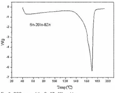
element indium is found to have dissolved in the "-Sn solder matrix. The DSC analysis shows that the Sn-8Zn-20In solder possesses solidus and liq-uidus temperatures (TS, TL) of 156.2 and 171.2, re-spectively, as shown in Fig. 3.
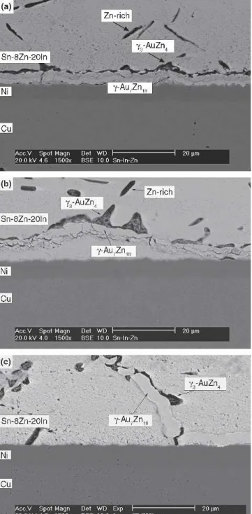
After reflow, a planar double layer of intermetallic compounds can be observed to have formed at the interface between the Sn-8Zn-20In solder and the Au/Ni/Cu pad (Fig. 4). It can also be seen in Fig. 4 that part of the intermetallic layer has floated away from the interface. The EDX analysis shows that the composition (at.%) of the outer intermetallic layer (shown in dark) is Au:Zn " 19.2:80.8, which corre-sponds to the #3 phase (AuZn4) in the Au-Zn equi-librium diagram. The inner layer (in gray) of the interfacial intermetallics has the composition Au:Zn " 28.4:71.5, which corresponds to the # phase (Au7Zn18). Although the Au thin film has dissolved and reacted with the liquid Sn-8Zn-20In solder in contact with the Ni/Cu pad, no Ni-Zn intermetallic compound can be found in Fig. 4.
In the case of the Sn-8Zn-20In BGA solder joints with Ag/Cu pads, the interfacial intermetallics
ap-Fig. 1. Microstructure of the as-cast Sn-8Zn-20In solder.
Fig. 2. DSC curve of the Sn-8Zn-20In solder.
Fig. 3. Temperature profile for the reflow operation of Sn-8Zn-20In solder BGA packages in this study.
Liu, Lin, Lin, and Chuang 148
pear as a thin layer of scallops. The composition (at.%), as analyzed by EDX, is Ag:Zn " 14.4:85.6, which corresponds to the $ phase (AgZn6) in the Ag-Zn equilibrium diagram. Similar to the case of the Au/Ni surface finish, the liquid Sn-8Zn-20In solder does not react further with the Cu pads after the exhaustion of the Ag thin film. When Fig. 4a and Fig. 5a are compared, it can be found that the re-flowed ball height for the case of the Ag/Cu pad is greater than that for the Au/Ni/Cu pad. The more vigorous collapse of the solder balls on the Au/Ni/Cu pads may be attributed to the rapid formation and migration of the #3/# intermetallic layer.
Figure 6 shows the morphology of intermetallic compounds in Sn-8Zn-20In solder joints with Au/Ni/ Cu pads after aging at 75°C for various time periods. It can be seen that the thickness of #-Au7Zn18 inter-metallics (gray, inner layer) decreases slightly, while the outer #3-AuZn4intermetallic layer (dark) grows noticeably with the increase of aging time. Accompanied by the growth of #3-AuZn4, the #3/# intermetallic double layer migrates toward the sol-der matrix. As evidenced by Fig. 6b, the needle-shaped Zn-rich precipitates in the Sn-8Zn-20In sol-der matrix join with the #3/# intermetallic layer, resulting in the growth of the #3-AuZn4phase. Fig-ure 6 also reveals that the swept region of the solder matrix behind the migrated #3/# intermetallic layer
has been swept cleaned of Zn-rich precipitates. The remaining "-Sn matrix contains only small amounts of Zn atoms, which might also react with the Ni/Cu pad to form Ni-Zn intermetallic compounds (Ni4Zn21 phase) at the solder/Ni interface, as reported, in a Sn-9Zn solder BGA packages with Au/Ni surface fin-ish after aging at 150°C.9 However, the Zn content in the remaining "-Sn matrix of the present Sn-8Zn-20In solder packages and the aging temperature are too low to result in an intermetallic thickness to be observed at the interface. In that case of Sn-9Zn packages,9the interfacial Ni-Zn intermetallics were also absent at the low aging temperature of 100°C. For Sn-8Zn-20In solder joints with Au/Ni/Cu pads, aging at 115°C results in a much more rapid growth of the #3-AuZn4phase, as shown in Fig. 7. With the increase of aging time at 115°C, breakage occurs at certain locations in the inner #-Au7Zn18layer, which causes the #3phase to grow across the # phase to the inner side of the intermetallic layer. Similar to the case with 75°C aging, the Ni-In intermetallic com-pounds cannot be observed at the "-Sn solder/Ni in-terface after aging at 115°C.
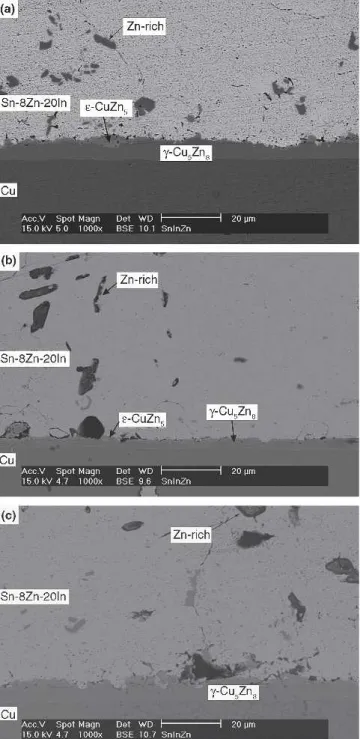
In the case of the Sn-8Zn-20In BGA specimens with Ag/Cu pads, their intermetallic reaction after aging is quite different from what is shown in Figs. 6 and 7 for the solder joints with Au/Ni/Cu pads. Figure 8 indicates that the thin layer of $-AgZn6 Fig. 4. Morphology of intermetallic compounds formed after the
intermetallic scallops formed at the as-reflowed in-terface vanishes after aging at 75°C for time periods longer than 300 h. Accompanied with the disappear-ance of $-AgZn6intermetallics at the interface, for-mation of an intermetallic double layer takes place as the Sn-8Zn-20In solder reacts with the Cu pad. The thicker inner layer, as analyzed by EDX, has a composition (at.%) of Cu:Zn"37.7:62.3, which corre-sponds to the #-Cu5Zn8phase in the Cu-Zn equilib-rium diagram. In addition, a thin layer of interme-tallic scallops can be observed ahead of the #-Cu5Zn8 phase. The EDX analysis indicates that the
compo-sition of the scallop-shaped intermetallic thin layer is Cu:Zn " 19.1:80.9, which corresponds to the $-CuZn4 phase in the Cu-Zn equilibrium diagram. From Figs. 8 and 9, it can also be seen that the $-CuZn4 intermetallic scallops are replaced by the #-Cu5Zn8thick layer with the increase of aging time and temperature. The #-Cu5Zn8 intermetallic layer grows even further as the time is increased. Along with the growth of #-Cu5Zn8 intermetallic com-pounds at the interface, the needle-shaped Zn-rich precipitates in the Sn-8Zn-20In solder matrix de-crease in quantity, as shown in Figs. 8 and 9. Fig. 6. Morphology of intermetallic compounds formed in
Sn-8Zn-20In solder BGA packages with Au/Ni/Cu pads after aging at 75°C for various times: (a) 100 h, (b) 300 h, and (c) 1000 h.
Fig. 7. Morphology of intermetallic compounds formed in Sn-8Zn-20In solder BGA packages with Au/Ni/Cu pads after aging at 115°C for various times: (a) 100 h, (b) 300 h, and (c) 1000 h.
Liu, Lin, Lin, and Chuang 150
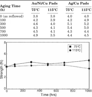
Ball shear tests for the as-reflowed Sn-8Zn-20In solder joints with Au/Ni/Cu pads show a bonding strength of 3.8 N, which increases slightly to about 4.5 N after aging at 75°C for various time periods (Table I and Fig. 10). At the aging temperature of 115°C, their ball shear strengths increase to about 4.0 N for the time periods of 100 h to 700 h and then drop to 3.5 N after a prolonged aging time of 1000 h. After ball shear tests, the as-reflowed and aged sol-der joints reveal ductile fractures across the solsol-der balls, as shown in Fig. 11. It is evidenced that the
material strength of Sn-8Zn-20In solder is lower than the solder/pad interfacial strength.
The as-reflowed Sn-8Zn-20In solder joints with Ag/Cu pads possess the ball shear strength of 4.0 N, which increases to about 5.2 N after aging at 75°C for 300 h and 500 h and then decreases to 4.4 N for aging times longer than 700 h, as shown in Fig. 12 and Table I. Aging at 115°C shows a tendency of ball shear strength similar to that for 75°C aging. The fractography of solder joints after ball shear tests also reveals ductile characteristics, as shown in Fig. 8. Morphology of intermetallic compounds formed in
Sn-8Zn-20In solder BGA packages with Ag/Cu pads after aging at 75°C for various times: (a) 100 h, (b) 300 h, and (c) 1000 h.
Fig. 9. Morphology of intermetallic compounds formed in Sn-8Zn-20In solder BGA packages with Ag/Cu pads after aging at 115°C for various times: (a) 100 h, (b) 300 h, and (c) 1000 h.
Fig. 11. In comparison with the immersion Ag solder joints, the relatively lower strength of the Sn-8Zn-20In solder joints with Au/Ni/Cu pads may be cor-related with the inhomogeneous microstructure of the latter due to migration of the #3/# intermetallic layer into the solder matrix. The interfacial $-CuZn5/#-CuZn8 intermetallics in the immersion Ag solder joints have induced no effect on the ball shear strengths due to the weaker Sn-8Zn-20In sol-der matrix. For most Sn-based solsol-ders, the element Ag is the dissolver that can aid in the formation of Ag3Sn particles in the solder, which will certainly strengthen the solder matrix. Yet, such a strength-ening effect does not occur in Sn-8Zn-20In solder joints with the immersion Ag surface finish, as the formation of scallop-type $-AgZn6 intermetallics at the solder/pad interface predominates over the dis-persion of Ag3Sn precipitates in the solder matrix.
CONCLUSIONS
The intermetallic reactions of Sn-8Zn-20In solder BGA packages with Au/Cu/Ni and Ag/Cu pads are investigated. After reflow, the Au thin film on the Au/Ni surface finish reacts rapidly with the Sn-8Zn-20In solder to form a #3-AuZn4/#-Au7Zn18 interme-tallic double layer. The #3/# intermetallic layer tends to float away from the solder/pad interface. During aging at 75°C and 115°C, the #3phase grows rapidly with the dissolution of Zn-rich precipitates in the solder matrix. However, the interfacial Ni-Zn intermetallics reported in the Au/Ni surface finished Sn-9Zn packages after aging at 150°C might be too
thin to be observed in the present Sn-8Zn-20In sol-der joints aged at 75°C and 115°C. In the case of the immersion Ag surface-finished Sn-8Zn-20In solder joints, a thin layer of $-AgZn6intermetallic scallops is formed at the interface after reflow. With further aging at 75°C and 115°C, the $-AgZn6intermetallics disappear, and a $-CuZn5/#-Cu5Zn8 double layer is formed at the solder/Cu interface. Increase of aging time causes #-Cu5Zn8 to grow. The inhomogeneous microstructure in the Au/Ni surface-finished Sn-8Zn-20In solder joints results in lower strengths
af-Table I. Ball Shear Strengths of the Sn-8Zn-20In Solder BGA Packages with Au/Ni/Cu and Ag/Cu
Pads after Various Aging Treatments Aging Time
(h)
Au/Ni/Cu Pads Ag/Cu Pads
75°C 115°C 75°C 115°C 0 (as reflowed) 3.8 3.8 4.0 4.0 100 4.2 3.9 4.2 4.9 300 4.6 4.0 5.1 5.2 500 4.3 4.1 5.4 5.0 700 4.5 4.1 4.3 4.4 1000 4.9 3.5 4.4 4.5
Fig. 10. Ball shear strengths of the Sn-8Zn-20In BGA packages with Au/Ni/Cu pads.
Fig. 11. Typical fractography of solder joints in Sn-8Zn-20In pack-ages with Au/Ni/Cu pads after ball shear tests: (a) as-reflowed and (b) aging at 75°C for 700 h.
Fig. 12. Ball shear strengths of the Sn-8Zn-20In BGA packages with Ag/Cu pads.
Liu, Lin, Lin, and Chuang 152
ter reflow and aging as compared to those of the immersion Ag solder joints.
ACKNOWLEDGEMENT
Special thanks go to the National Science Council, Taiwan (Grant No. NSC-93-2815-C002-019E) for sponsorship of this research.
REFERENCES
1. H.J. Lau, C.P. Wong, N.C. Lee, and S.W. Ricky Lee,
Elec-tronics Manufacturing with Lead-Free, Halogen-Free & Conductive-Adhesive Materials (New York: McGraw-Hill
Handbooks, 2003), pp. 14.1–14.36.
2. K. Zeng and K.N. Tu, Mater Sci. Eng. R38, 55 (2002). 3. M. McCormack, S. Jin, and H.S. Chen, J. Electron. Mater.
23, 687 (1994).
4. M. McCormack and S. Jin, J. Electron. Mater. 23, 635 (1994).
5. Y. Cui, X.J. Liu, I. Ohnuma, R. Kainuma, H. Ohtani, and K. Ishida, J. Alloys Compounds 320, 234 (2001).
6. S.W. Yoon, J.R. Son, H.M. Lee, and B.J. Lee, Acta Mater. 45, 951 (1997).
7. Y.C. Chan, M.Y. Chiu, and T.H. Chuang, Z. Metallkd. 93, 95 (2002).
8. R.K. Shiue, L.W. Tsay, C.L. Lin, and J.L. Ou, Microelectron.
Reliab. 43, 453 (2003).
9. H.J. Lin and T.H. Chuang, J. Electron. Mater. 35, 154 (2006).