HIGH SPEED MEMORY EFFICIENT EBCOT ARCHITECTURE FOR JPEG2000
Hung-Chi Fang, Tu-Chih
Wang,
Chung-Jr Lian, Te-Ha0 Chang and Liang-Gee Chen
DSP/IC Design Lab
Graduate Institute of Electronics Engineering and Department
of
Electrical Engineering
National Taiwan University
I , Sec.
4,
Roosevelt Rd., Taipei
106, Taiwan
{honchi, eric, cjlian, thchang, Igchen} @video.ee.ntu.edu.tw
ABSTRACT
This paper presents a high speed, memory efficient architecture of embedded block coding with optimized truncation (ERCOT) tier-l in JPEG2000. By parallel coding all the bitplanes, the state variable memory can be eliminated. The proposed architecture can process 50 M coefficients per second at
LOO
MHz, which can realtime encode 720p resolution of HDTV picture format at 30 fps.1.
INTRODUCTIONJPEGZOOO [I]. 121 is the latest standard for still image coding. It is well known by its excellent coding performance and abundant features [3]. such as region of interest (ROI), scalability, error re- silience, etc. Although these features can also be provided in JPEG standard, some functionalities require supports at decoder side. On
the other hand, all these powerful tools can be provided in a single JPEG2000 bitstream. For example, an image can b e coded in loss-
less mode for storage and be retrieved at different bitrates. How- ever, the high computational complexity that grants such excellent performance and rich features restricts the real time applications
of
JPEG2000.
EBCOT is the most complicated pan in IPEG2000 [4]. There are various architectures of EBCOT proposed in previous arts [4], [5], 161, [ 7 ] . All of them process the block bitplane by bitplane, which is the default mode of JPEG2000 block coding. Although the compression ratio of the default mode is the highest, it has some drawbacks. First, the default mode performs bad at error re- silience since the arithmetic encoder (AE) terminates at end of the code block only. When an error occurs somewhere in a code block all the rest data in the code block becomes useless. Second, the hardware implementation of the default mode requires needs a lot of memory to store the state variables. The memory requirement analysis in [8] shows that 20K bits of internal memory are needed for the block coding with 64 x 64 code block size.
The discrete wavelet transform (DWT), adopted by JPEG2000, is a word-level processing. Since the block coding follows DWT and processes in a bitplane by bitplane manner, there should be some data conversion between these two parts. T h e block coder access one bit of the coefficient at one time. If the coefficient bitwidth is
n,
the subband memory will be accessedn
times and the power consumption will be large.All these drawbacks can be solved with parallel processing. As shown in the following sections, all the memory for state vari- ables can be avoided, The power consumption of memory access
0-7803-776l-3/03/$17.00 82003 IEEE
II-I36
(a) (b)
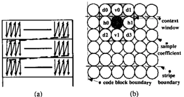
Figure I: (a) Scan pattern for bitplane coding. (b) Context window for context formation.
can be reduced since the proposed block coder processes DWT co- efficients at word-level as well as D W . Error does not propagate across passes since AE terminates at each coding pass in parallel mode.
Section 2 reviews the ERCOT algorithm. The proposed EBCOT architecture is presented at section 3. Implementation result and comparisons are shown at section 4. Section 5 gives a brief conclusion ofthis paper.
This paper is organized as follows.
2. EBCOT ALGORITHM
JPEG2000 adopts ERCOT coding as its entropy coding algorithm. The basic unit of EBCOT coding is a rectangle called code block. Its size is typically 64 x 64 or 32 x 32. A code block is further divided into stripes that are 4 x N rectangles, where N represents code block width. The scan order is first column by column within a stripe and then row by row for stripes as shown in Fig. ](a). The context of a sample coefficient is formed according to the signifi- cant state of itself and its eight neighbors within a 3 x 3 window, as shown in Fig. I(b).
The order of bitplane coding is from the MSR to the LSR. Each bitplane contains three coding passes called significant prop- agation pass (pass I), magnitude refinement pass (pass 2) and clean up pass (pass 3). The exception is the MSB bitplane of the code block, which has only one pass (pass 3). By examining the sig- nificant states of the nine sample coefficients in the context win- dow, the coding pass
of
the central sample coefficient can be de- cided. The context is generated from the significant state of its eight neighbors, each labelled as h0, h l . etc. in Fig. I(b). TheseFigure 2 Performance comparison of default and parallel mode
G n B
Figure 3: Architecture of Parallel EBCOT
eight values are called HVD for a short hereafter. Finally, AE processes the context and decision pair and outputs the bitstream segment.
There are mainly two differences between the default and par- allel EBCOT coding algorithms. First, AE should make termina- tion at the end of every coding pass in parallel mode. By doing so, each pass of the same bitplane can he coded in parallel. Sec- ond, the sample Coefficients that come from the lower stripe are considered as insignificant in parallel mode.
The performances of these two mode are almost the same as shown in Fig. 2. The images are of size 512 x 512 and are coded with 53 filter. The average PSNR degradations for 53 and 97 filters are 0.17dB and 0.19dB respectively. Although the performance of the parallel mode is slightly poorer than the default mode, the parallel mode has some advantages. It is more robust in error- prone environment than the default mode since AE terminates at the end of every pass. When an error occurs, it influences only the rest data in the same pass rather than the whole code block in the default mode. And it requires only one scan to code the three pass, while default mode needs three scans. In addition. it is much easier for tier-2 implementation, which makes optimized truncation by terminating AE at each pass.
3. PARALLEL EBCOT ARCHITECTURE The proposed high speed and memory efficient parallel EBCOT architecture is shown in Fig. 3. There are five major functional blocks in our design. All of them process independently over hit- planes except the MPASS module. The subband data after DWT is fed into MPASS where the coding pass number of the MSB bit- plane is calculated. Then, the pass and HVD data of all bitplanes
Figure 4 Gobang Register Bank. The circles represent registers that contains input data.
are determined in the PHVD module. The CF module maps the pass and HVD data into context-decision pairs and passes them to the FIFO. Each AE handles two FIFO inputs and generates output hitstreams.
The number of AE can he folded by two due to the properties of DWT coefficients in EBCOT algorithm. The magnitudes of co- efficients after DWT are not equal distributed and large coefficients are much less then small one. And the number of contexts in
a
bit- plane decreases dramatically from LSB to MSB. By these obser- vations, we use one AE to deal with two bitplanes. Bitplane i and Bitplane (n - 1 - i) use the same AE to encode bitstream, which makes the hardware cost of AE half. The number n represents the number of bitplane supported by the proposed architecture. 3.1. Gabang Register BankThe input data is first stored and shifted in the Gobang Register Bank (GRR). as shown in Fig. 4. The GRR reorder the input data to other modules to meet IPEF2000 scan order. The data is first rotated within each column to match the data flow of one column in the stripe
.
When a column in the stripe is coded, i.e. every four clock cycles, the data sample is shifted to next column for the next column in the stripe. The two 3 x 3 windows, MPASS and PHVD, indicate which registers are used in the MPASS and PHVD module. The GRB contains 20 word-level registers instead of 24 registers since the sample coefficients from next stripe are considered zero.3.2. MPASS
The major difference between parallel mode and default mode im- plementations is the number of scans. Our parallel architecture requires only one scan instead of three in the default mode. A
problem
of
determining significant state occurs when processing three passes in one scan. Fig. 5 shows an example ofthis problem. The meanings of circles are the same as those in Fig. I(b). The value in circle represents the coefficient value. A gray circle rep- resents that the coefficient has been significant in upper bitplane while a white circle means not significant. Referring to the truth table in this example, the contribution of coefficient at position VI-
C 1 1 I 2 I 2 3 2 1 3 1 1 0 2 1 1 1 0 1 1 3 3 1 0 0 a i s 1 1 1- -
vl 63 1 1 IX I >
0 IFigure 5 : Example of relationship between coding pass and signif- icant contribution.
is influenced by the coding pass it belongs. As a result we must have the pass information of all the neighbors in order to calculate the correct HVD data. However, we need not to get the pass infor- mation of every bitplane. Because the significant state is always 1 in bitplane lower than MSB and is always 0 in bitplane higher than MSB regardless of the coding pass. The MSB is only one hitplane that the updated significant state differs to the one before update.
The MPASS module is designed to solve this problem. The block diagram of MPASS is shown in Fig.
6 .
The circles represent the registers in GRB. Each square represents a processing element(PE) and the pseudo-code is shown in Fig. 6 . The coding pass of the MSB of the central coefficient is called
“mp”
andis
merged into the data flow with the coefficient in GRB. T h e signal “mp.w” is the mp of the neighboring coefficient since it is coded before the central coefficient. If all the contributions of eight PES are zero, mp of the central coefficient is zero; otherwise, it is one.3.3. PHVD
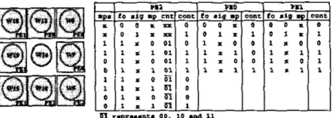
PHVD module determines the codinp pass andcalculates the HVV values to form the context. The block diagram of PHVD and the truth table of the PES are shown in Fig. 7. The mps and mp indi- cate the coding pass of MSB of the central and neighboring coef- ficients. The input “fo” indicates whether the bitplane is the MSB. The input “sig” indicates if the bitplane is lower than MSB. The in- put “cnt” is the counter corresponding to the position of the central coefficient in the stripe. When cnt is zero, the central coefficient in MPASS module is the first pixel in a column. Due to pipeline, the central coefficient in PHVD is the first coefficient in the stripe when cnt is 1. The outputs of the PES are call contribution (cont). Both the coding pass and HVD values are determined by the con- tribution of these neighbors. There are three kinds of PES in PHVD which calculate the contribution of the corresponding sample co- efficient. PE0 is responsible
for
the neighbor which is coded afterFigure 7: Block diagram of PHVD module.
i f 1 the sample coefficient is below the HSB I
coding pass
-
pass 2 ;if 1 all the neighboxs are insignificant >
coding pass ~ pass 3 ;
coding pass
-
p a s s 1;Figure
8:
Pseudo code which determines the coding pass.the central coefficient. And PE1 is responsible for the neighbor which is coded before the central coefficient. The coefficient cor- responding to PE2 is a special case. It comes from the previous stripe when cnt is I and from the same stripe at other cases of cnt. So it is coded before the central coefficient when cnt equals 1 hut after the central coefficient at other cases. The pseudo code which determines the coding pass of the central coefficient is shown in Fig. 8. T h e outputs of the PES are grouped as horizontal (HI, ver- tical (V) and diagonal (D) as the context window in Fig. I(b). And the HVD data is calculated by adding the contributions in the same group. Note that the PHVD window is not the same as in MPASS since all the coefficients in the PHVD window must go through MPASS module.
3.4. Context Formation
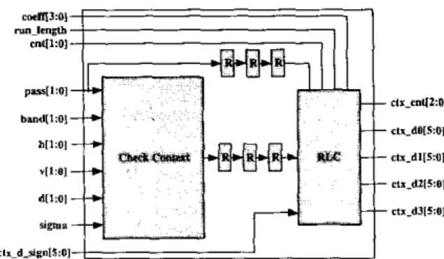
The block diagram of context formation module is shown in Fig.
9.
The coeff indicates the four sample coefficients in the same column of a stripe. RunJength is an flag indicating whether the column should be coded in run-length mode or not. Sigma is also a Rag representing the first magnitude refinement. Band indicates which subband the code block belongs. C t x d r is the context and decision of the sign of the sample coefficient,The C F module works as follows. First, pass and HVD data come from previous module, PHVD, are used to check the context of the sample coefficient. The
R
module isa
register. T h e ZCand MR module map the pass and HVD data into zero coding and magnitude refinement. In order to cope with the Nn-length code, we must keep the first three contexts in a column of stripe. Finally, the contexts and decisions are generated by the run length code (RLC) module. Note that there are variable number
of
contexts generated, from 0 to 4, when coding a sample coefficient.3.5. FIFO
Because the output rate of C F module is not identical with that of AE, we need a fifo between these two modules. The length
the processing time of the proposed architecture is not proportional to the number of bitplanes.
Figure 9: Block diagram of context formation module.
of fifo is chosen as fifteen, experimentally. Each fifo contains a pass (2 bits) and four context-decision pair (each 5 bits). Because the coding pass is indicated explicitly, the number of hit used to represent context is reduced to 4 bits. 10 FlFOs are used since there are 10 magnitude bitplanes in our architecture.
3.6. Arithmetic Encoder
Although one sample coefficients belongs to only one of three passes, we must have three sets of probability estimation table and other state variables in the AE. The memory requirement is double since we have two bitplane that use a common AE. Note that the probability estimation tables are separated by coding passes and some context that will not appear in the certain coding pass can be eliminated. For example, run-length context will nul appear in pass 1 and pass 2 and should be removed from the tables. By doing so. the area of AE can he further reduced.
4. IMPLEMENTATION RESULT AND COMPARISONS
4.1. Implementation
The proposed architecture is synthesized using TSMC 0.35 p n
CMOS tcchnolugy. The gate count and memory requirement of our proposed architecture are listed i n Table I . The size of the code block is 64x64 and the coefficients bitwidth is I 1 bits.
CF 14803 64x 12
FIFO NA (15X22)XIO
AE 11536x5 (72x 6 ) x 5
4.2. Comparisons
Table 2 lists the processing time of a code block. The number N represents the width of the code block and n represents the number of bitplanes. As we can see, the number of speed-up is about n than Chen's and Chiang's and is almost 30 than Taubman's if the number of non-zeru bitplane is less than 6. And when the number of non-zero bitplanes is lager than 6, the speed up is half. Besides,
Table 2: Processing Time Comparison with Other Architectures average processing time
(3 x (n- I ) + l ) x N2
[91'S
[4l's 1.3 x nx N2
~ 7 1 3 n x N Z
proposed (I+&) x N2
6 is about 0.1 to 0.2 when the nonzero bitplanes are smaller than or equal to 5 and close to 1 when larger than 5.
5. CONCLUSIONS
In this paper, a high performance, memory-saving parallel archi- tecture of EBCOT tier-l for JPEG2000 is proposed. All the bit- planes are coded in parallel in our architecture. The state vari- able memory can be eliminated by the proposed method. And the processing rate is several times then other architectures previously proposed in the literature. The proposed architecture processes
50M coefficients per second at IOOMHz, regardless of the bitwidth of the coefficients, and can encode lossless HDTV 720p resolution pictures at 30 fps in real time.
6. REFERENCES
[ I ] ISO/IEC JTCI/SC29/WGI N1855. JPEC 2000 Part I: Final Drafr Inrernarional Standard (lSO/lEC FDIS15444-I), Aug. 2000.
[21 ISOIIEC JTCI/SCZWWGI N1271, JPEGZOOO Requirements
and Profiles, Mar. 1999.
[31 Skodras A.. Christopoulos C., and Ebrahimi T.. "The JPEG 2000 Still Image Compression Standard:' IEEE Signal P m -
cessing Mag., vol. 18, no. 5 . pp. 3 6 5 8 , Sept. 2001.
[4] K. F. Chen, C. J. Lian, H. H. Chen, and L. G. Chen, "Anal- ysis and Architecture Design of E B C m for JPEG-2000," in
IEEEE Inr. Symp. Circuits and Sysrems (ISCAS 2001). 2001,
pp. 765-768.
151 Kishore Andra, Chaitali Chakrabarli, and Tinku Acharya, "A High Performance JPEG2000 Architecture," in IEEEE Inf.
Symp. Circuits and Systems (ISCAS 2002), 2002, pp. 765-768. [61 Y. T. Hsiao, H.
D.
Lin, and C.W.
len, "High-speed Mem-ory Saving Architecture for the Embedded Block Coding in IPEG2000," in IEEEE Inr. Symp. Circuits and Sysrems ( I S -
CAS 2002). 2002, pp. 133-136.
"Efficient Pass- Parallel for EBCOT in JPEG2000," in IEEEE Int. Symp. Cir- cuits and Systems (ISCAS 2002), 2002, pp. 773-776.
[E]
D.
Taubman, E. Ordentlich, M. Weinherger, and G. Serourssi, "Embedded Block Coding in JPEG 2000," in Proc. IEEE Int.Conf: linage Processing (ICIP 200O), 2000, pp. 33-36.
191 ISOIIEC JTCl/SC2Y/WGl N1684, JPEC-2000 Verificarion
Model 7.0 (Techinical Description), Apr. 2000. [7] J. S . Chiang, Y. S . Lin, and C. Y. Hsieh.