642 IEEE TRANSACTIONSON CIRCUITSAND SYSTEMS,VOL.CAS-33,N0. &JUNE 1986
Transactions Briefs -
An Alternative Approach for Designing Maximally Flat Low-Pass Filters with Multiple Order
Imaginary-Axis Zeros CHE-HO WEI
Abstruct -A systematic procedure is introduced to design a maximally flat low-pass filter with multiple order imaginary-axis zeros. The filter characteristics is specified by the passband and stopband edge frequencies, maximum loss in passband and minimum loss in stopband. This approach can lead to an optimal design of this class of filters.
I. INTRODUCTION
Most of the previous studies on designing a maximally flat lowpass filter with multiple-order imaginary-axis zeros [l]-[?I are based on the filter’s cutoff slope and minimum loss in the stopband. The filter so designed often depends on the choice of the position of the imaginary-axis zeros. Recently, a procedure for evaluating all the parameters of this kind of filters from the given specifications in ‘the passband and stopband has been introduced by Varanasi and Dutta Roy [4].
In this brief, an alternative approach is introduced to design this kind of filters, specified by the passband’s maximum loss
A max7 stopband’s minimum loss A,i,, passband edge frequency
wp and stopband edge frequency wS. The transfer function is derived from the modified Butterworth filter of Rakovich and Popovich [5]. It is similar to the derivation of the inverse Chebyshev low-pass function from the classical Chebyshev low- pass function [6]-[8]. By this approach, an optimal design of this kind of filters can be obtained.
II. MODIFIED BWTTERWORTHFILTER
The classical Butterworth low-pass filter has maximally flat attenuation response at w = 0 [S]. A class of low-pass filters with zero loss at w = 0 and at some frequency within the passband, known as modified Butterworth filter, has been studied [5]. In general, the magnitude squared function can be written in the form
1
IW412 =
lir2(~*)“2m(~~0*-1)** (1)
(+l)2m
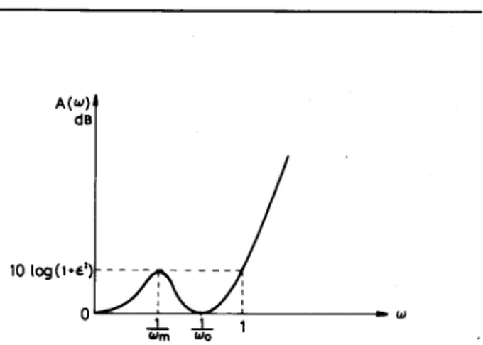
where m is an integer such that 2m < n and o0 Z= 1. c* is a constant controlling the maximum passband loss. The loss of the filter in decibels is given by
A(w) =lOlog[I+c*L(W*)]
where
L(w2) = (co*)“-2m(W;k? -l)*, I ^ \7m
(06 -l)- (3)
Manuscript received January 17,1985; revised October 31, 1985.
The author is with the Electronics Engineering Department, National Chiao Tung University, Hsin Chu, Taiwan, Republic of China.
IEEE LogNumber8607934.
A(‘4 de
Fig. 1. Loss characteristics of a normalized modified Butterworth low-pass filter.
TABLE I
ZERO-L• SSFREQUENCY~/W,, ANDMAXIMUMPASSBAND-LOSS FREQUENCY~/W,,, OFTHENORM~LIZEDMODIFIEDBUTTERWORTH FILTERSFOR n = 4-12 1 I n In 00 7 3 1 0.8660 0.5000 4 1 0.9102 0.6436 5 1 0.9323 0.7221 2 0.8207 0.3670 6 B 0.9456 0.8660 0.7721 0.5000 7 1 0.9545 0.8067 2 0.8926 0.5843 3 0.7969 0.3012 8 2 0.9609 0.9102 0.8322 0.6436 3 0.8391 0.4195 9 1 0.9657 0.8517 2 0.9227 0.6878 3 0.8660 0.5000 4 0.7820 0.2607 10 1 0.9695 0.8671 2 0.9323 0.7221 3 0.8550 0.5597 4 0.8207 0.3670 11 1 0.9725 0.8797 2 0.9396 0.7496 3 0.8992 0.6062 4 0.8468 0.4423 5 0.7717 0.2327 12 1 0.9750 0.8900 2 0.9456 0.7721 3 0.9102 0.6436 4 0.8660 0.5000 5 0.8073 0.3296
The filter has zero loss at o = 0 and w = l/w,,. The first n - 2 m
- 1 derivatives of L( w*) with respect to o* at o = 0 and the first
2m - 1 derivatives of L( w*) with respect to o* at o = l/w,, are all equal to zero.
The loss characteristics of (2) is shown in Fig. 1. The frequency l/%l 9 corresponding to an analytical maximum of passband loss, obtained from the condition (dL(~*))/do = 0 at w =1/w,, is given by
1 n-2m ‘I2 1
-=- -
%I i n 1 WO
(4)
IEEE TRANSACTIONSON CIRCUITSAND SYSTEMS,VOL.CAS-33,NO.'$JUNE 1986 643 (b) T(iw)l' ) 1-IT(W , --- --- - a’ 2 0 I, -t---1 w 3-, 8 ’
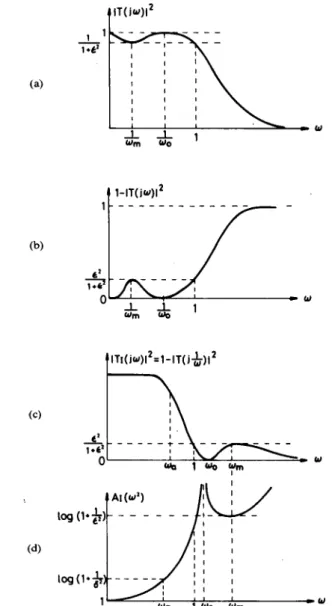
Fig. 2. Pictorial derivation of a normalized maximally flat filter with multi- ple-order imaginary-axis zeros from a normalized modified Butterworth filter.
The loss at o =1/w,,, is then obtained as (2m)‘“(n -2m)n-2m
n”
. (a; $(u;)n-*m . (9
1
The parameter or, can be chosen such that A(1) = A(l/w,) =
lOlog(l+ r*). If the maximum passband loss is equal to lOlog (1 + c*), then the passband edge frequency oP is equal to unity. The normalized value of l/o0 can be found from the roots of the following equation:
2”
?I” - (n-2m)n-2m(2m)2m.
The values of l/o0 and l/o,,, for n = 3 - 12 and 2m < n are given in Table I.
TABLE II
SELECTIVITYPARAMETER k OFTHEMAXIMALLYFLATLOW-PASS FUNCTIONWITHMULTIPLE-ORDERIMAGINARYAXISZEROS(A),
BUTTERWORTHAPPROXIMATION(B)ANDIWERSECHEBYSHEV APPROXIMATION(C) A,,max =3 dB AND A,.,,,=30 dB
(A) (B) CC) n m k=w, n k=W, ,, k=lOa 4 1 0.5998 3 0.3160 3 0.4720 5 1 0.6794 4 0.4217 4 0.6297 2 0.6768 5 0.5012 5 0.7329 6 1 0.7331 6 0.5623 6 0.8008 2 0.7457 7 0..6105 7 0.8468 7 1 0.7716 : 0.6494 8 0.8791 2 0.7905 0.6813 9 0.. 9024 3 0.7688 10 0 7079 10 0.9197 8 1 0.8005 11 0.7305 11 0.9328 2 0.8220 12 0.7499 12 0.9431 3 0.8116 13 0.7667 9 1 0.8229 14 0.7814 2 0.8451 15 0.7943 3 0.8408 16 0.8058 4 0.8198 17 0.8161 10 1 0.8408 18 0.8254 2 0.8631 19 0.8338 3 0.8621 20 0.8414 4 0.8492 21 0.8483 11 1 0.8555 22 0.8547 i 0.8773 0.8783 23 24 0.8660 0.8606 4 0.8700 5 0.8521 12 1 0.8677 : 0.8889 0.8911 z 0.8856 0.8737
III. DERIVATION OF MAXIMALLY FLAT LOW-PASS FUNCTION WITH MULTIPLE-ORDER IMAGINARY-AXIS
ZEROSFROMMODIFIEDBUTTERWORTHFILTER
Similar to the derivation of the inverse Chebyshev low-pass function from the classical Chebyshev low-pass function [6], maximally flat low-pass function with multiple-order imaginary- axis zeros can be derived from ]T( jo) ]*, as shown in Fig. 2.
The magnitude squared function ]T1( &I)]* of the derived low-pass filter is given by
and then 2 = l-r,. [ 1 ,*+lJ; -1)2m -l (J - ,)2m
1
co
(8)
Foragivensetof(n,m,w,,r *, S*), the passband edge frequency can be obtained by solving the following equation:
The values w,, for n = 4 - 12,2m < n, Al,min = 30 dB, A[,,,= = 3
dB, are calculated and given in Table II. The values of W, for the classical Butterworth low-pass filter with n = 3 - 24 and the inverse Chebyshev low-pass filter with n = 3 - 12 are also given in this table for comparison.
The value k = o,/w, is known as the selectivity of a low-pass filter [9]. The larger k is, the more selectivity, i.e., steeper, the
64’ IEEE TRANSACTIONS ON CIRCUITS AND SYSTEMS, VOL. CAS-33, NO. 6, JUNE 1986
0.0 0.2 0.4 0.6 0.8 1.0 1.2 1.4
Fig. 3. Time-delay characteristics of the three low-pass filters. (a) Butter- worth filter, n = 22. (b) Maximally flat low-pass filter with multiple order imaginary axis zeros n = 10, m = 2. (c) Inverse Chebyshev filter, n = 8.
5
response. For o, = 1, k = L+, . It is interesting to note that, for a given n, the largest selectivity occurs when m is equal to n/2 or an integer close to n/2. It may be pointed out that the number of finite imaginary-axis zeros in the nth order inverse Chebyshev low-pass filter is n/2 or (n - 1)/2, depending on n is even or odd number.
IV. DESIGN PROCEDURE AND EXAMPLE
Suppose it is required to design a maximally flat low-pass filter with multiple order imaginary-axis zeros, given that
The specified passband edge frequency and stopband edge frequency are wP and ws, respectively. Then
1
,2 = 1()0.lbi, _ 1 md -$ = 1(pl4m 1 - 1.
The desired selectivity k is equal to tip/w,. The loss function will be of the form given by (8).
The first step is to find the corresponding normalized filter, i.e., w, is set to unity. Equation (9) can be used to find the smallest (n, m) such that w, is equal to or larger than k. To find the optimal values of (n, m), arbitrary initial values of (n, m) are
first given. The value o. is found from Table I or by solving (6). Then (9) is solved to obtain the corresponding 0,. Check if this o, is equal to or larger than k. By several iterations, optimal values of (n, m) can be obtained. After the normalized filter function has been found, frequency transformation [8] can be applied to obtain the required filter function.
For example, Al,,,= = 3 dB, A,,min = 30 dB and k = w,/w, =
0.85, the optimal values of n and m are n =lO, m = 2. To design a low-pass filter with the same specifications by Butterworth function and inverse Chebyshev function, the orders of the re- quired filter function are 22 and 8, respectively. This is also shown in Table II. The Q-factors Q, of the critical pole pair (the nearest to the imaginary axis) [lo] of the corresponding filter functions are obtained as
Q, = 7.01
= 5.30 = 5.49
for Butterworth function n = 22, for inverse Chebyshev function n = 8, for maximally flat low-pass function with
multiple-order imaginary-axis zeros n = 10, m = 2.
The required Q,. of the maximally flat low-pass filter with multi- ple-order imaginary-axis zeros is only slightly larger than that of the corresponding inverse Chebyshev filter, but smaller than that of ‘the Butterworth filter. The phase linearity of a filter can be illustrated by the corresponding time-delay performance of its transfer function. From Fig. 3, it can be seen that the phase linearities of these three filters in the passband are comparable.
REFERENCES
[l] A. Budak and P. Aronhime, “Maximally flat low-pass filters with steeper slopes at cutoff,” IEEE Trans. Audio Electroacoust., vol. AU-18, pp.
63-66.Mar.1970.
[2] S. C. Dutta Roy, “On maximally flat sharp cutoff low-pass filters,”
IEEE Trms. Audio Elqctroacoust. vol. AU-19, pp. 58-63, Mar. 1971. [3] C. H. Wei, “Design of sharp cutoff low-pass maximally flat RC active
filters by cascading third-order blocks,” IEEE Trans. Circuits Syst., vol. CAS-27, pp. 411-413, May 1980.
[4] P. Varanasi and S. C. Dutta Roy, “Design of maximally flat sharp cutoff low-oass filters.” r Proc. IEEE. vol. 69. DD. 473-474. Aor. 1981. [5] B. D. Rakovich and M. V. Popovich, A 1 “Modified Bu;teAorth filters,” Int.
J. Elecrrdn.:vol. 44. no. 4. DD. 435-W. 1978.
[6] D. S. Humihreys, The An&is, Design and Synthesis of Electrical Filters.
Englewood Cliffs, NJ: Prentice-Hall, 1970.
[7] R. W. Daniels, Approximation Methodr for Electronic Filters. New York: McGraw-Hill, 1977.
181 M. E. Van Valkenburg, Analog Filter Design. New York: Holt, Rine- . .
hart and Winston, 198%
[9] G. C. Temes and J. W. Lapatra, Introduction to Circuit Synthesis and Design. New York: McGraw-Hill, 1977.
[lo] A. Premoli, “The MUCROMAF polynomials: An approach to the maxi- mally flat approximation of RC active filters with low sensitivity,” IEEE Trans. Circuit Theov, vol. CT-20, pp. 77-80, Jan. 1973.
Multifrequency Measurement of Testability with Application to Large Linear Analog Systems G. IUCULANO, A. LIBERATORE, S. MANE-MT, AND
M. MARINI
AMract -With increasing electronic circuit complexity, assessing the testability features becomes a necessity during the design, implementation, and operational or maintenance phases of an analog system.
Manuscript received April 17, 1985; revised October 1, 1985.
The authors are with the Department of Electronic Engineering, University of Florence, 50139 Firence, Italy.
IEEE Log Number 8607935.