\
PERGAMON International Journal of Heat and Mass Transfer 31 "0888# 882Ð0995
9906Ð8209:87 Þ 0887 Elsevier Science Ltd[ All rights reserved[ PII] S 9 9 0 Ð 6 8 2 0 " 9 8 # 7 9 9 1 0 Ð 6 7
Condensation heat transfer and pressure drop of refrigerant
R!023a in a plate heat exchanger
Yi!Yie Yan\ Hsiang!Chao Lio\ Tsing!Fa Lin
Department of Mechanical En`ineerin`\ National Chiao Tun` University\ Hsinchu\ Taiwan Received 01 March 0887^ in _nal form 08 June 0887
Abstract
An experimental refrigerant loop has been established in the present study to measure the condensation heat transfer coe.cient hrand frictional pressure drop DPfof R!023a in a vertical plate heat exchanger[ Two vertical counter ~ow
channels were formed in the exchanger by three plates of commercialized geometry with a corrugated sinusoidal shape of a chevron angle of 59>[ Down~ow of the condensing R!023a in one channel releases heat to the cold up~ow of water in the other channel[ The e}ects of the refrigerant mass ~ux\ average imposed heat ~ux\ system pressure "saturated temperature# and vapor quality of R!023a on the measured data were explored in detail[ The results indicate that at a higher vapor quality the condensation heat transfer coe.cient and pressure drop are signi_cantly higher[ A rise in the refrigerant mass ~ux only causes a mild increase in the hrvalues for most cases[ The corresponding rise in the DPfvalue
is slightly larger[ Furthermore\ it is noted that the condensation heat transfer is only slightly better for a higher average imposed heat ~ux[ But the associated rise in DPfis larger[ Finally\ at a higher system pressure the hrvalue is found to
be slightly lower[ But the e}ect of the system pressure on DPfis small[ Correlations are also provided for the measured
heat transfer coe.cients and pressure drops in terms of the Nusselt number and friction factor[ Þ 0887 Elsevier Science Ltd[ All rights reserved[
Nomenclature
A heat transfer area of the plate ðm1Ł
b channel spacing ðmŁ
Bo boiling number\ dimensionless\ eq[ "23# cp speci_c heat ðJ:kg >CŁ
Dh hydraulic diameter ðmŁ
f friction factor
` acceleration due to gravity ðm:s1
Ł G mass ~ux ðkg:m1sŁ
Geq equivalent all liquid mass ~ux\ eq[ "24#
h heat transfer coe.cient ðW:m1>CŁ
ifg enthalpy of vaporization ðJ:kgŁ
k conductivity ðW:m >CŁ
L channel length from center of inlet port to center of exit port ðmŁ
LMTD log mean temperature di}erence ð>CŁ
Corresponding author[ Tel[] ¦775!24601010!44007^ Fax] ¦775!24619523^ E!mail] u7303702Ýcc[nctu[edu[tw[
Nu Nusselt number\ dimensionless P pressure ðMPaŁ
Pc critical pressure ðMPaŁ
Pr Prandtl number Q heat transfer rate ðWŁ
qwý average imposed wall heat ~ux ðW:m1Ł
Rwall heat transfer resistance of the wall
Re Reynolds number\ GDh:m0\ dimensionless
Reeq equivalent all liquid Reynolds number\ eq[ "22#
T temperature ð>CŁ
U overall heat transfer coe.cient ðW:m1>CŁ
u velocity ðm:sŁ
v speci_c volume ðm2kgŁ
w channel width of the plate ðmŁ W mass ~ow rate ðkg:sŁ X vapor quality[ Greek symbols DP pressure drop DT temperature di}erence
r density ðkg:m2Ł m viscosity ðN s:m1 Ł[ Subscripts de deceleration ave average
c\ h at cold side and hot side of the test section ele elevation
exp experiment f friction
fg di}erence between liquid phase and vapor phase g vapor phase
i\ o at inlet and exit of test section l liquid phase
lat\ sens latent and sensible heats
m average value for the two phase mixture or between the inlet and exit
man the test section inlet and exit manifolds and ports p pre!evaporator
r refrigerant tp two!phase w water
wall wall:~uid near the wall[
0[ Introduction
It is well recognized that the quick destruction of the ozone layer in the earth atmosphere noted recently has been primarily related to the wide use of the chloro! ~uorocarbon "CFC# refrigerants\ which have been employed as the working ~uids in many refrigeration\ air conditioning and heat pump systems or as cleansing ~uids for processing microelectronic devices[ Under the man! date of the Montreal Protocol\ the use of CFCs had been phased out and the use of HCFCs will also be phased out in a short period of time[ Therefore\ we have to replace the CFCs by new alternative refrigerants[ In order to properly use these new refrigerants\ we need to know their thermodynamic\ thermophysical\ ~ow and heat transfer properties[ Speci_cally\ we realize that a much more detailed understanding of the ~ow boiling and con! densation heat transfer of new refrigerants "R!023a\ R! 014\ R!041\ etc[# is very important in the design of evap! orators and condensers used in many current refriger! ation and air conditioning systems[ In the present study we intend to carry out an experimental study to measure the condensation heat transfer data for the ~ow of refrigerant R!023a in a vertical plate heat exchanger[ In particular\ measurements of condensation heat transfer coe.cient and pressure drop will be conducted for refrigerant R!023a[
A brief review of literature relevant to the present study is given in the following[ For in!tube condensation\ Schlager et al[ ð0Ł used R!11 as the working ~uid and three micro!_nned tubes with an outer diameter of
01[6 mm were tested[ A smooth tube was also tested to establish a basis for comparison[ The average conden! sation heat transfer coe.cients of the micro!_nned tubes were 0[4 to 1[9 times larger than those in the smooth tube[ Micro!_nned tubes having 8[4 mm OD and 7[8 mm maximum ID were also tested ð1Ł[ The condensation heat transfer enhancement factors were between 0[3 and 0[7 while the pressure drop penalty factors ranged from 0[9 to slightly higher than 0[1[
Later\ Eckels and Pate ð2Ł examined the in!tube ~ow evaporation and condensation heat transfer for refriger! ants R!023a and R!01[ The heat transfer coe.cients were measured in a horizontal\ smooth tube with an inner diameter of 7[9 mm[ For similar mass ~uxes\ R!023a showed a 14 to 24) higher heat transfer coe.cient when compared with R!01 for condensation[ Torikoshi and Ebisu ð3Ł experimentally investigated evaporation and condensation heat transfer and pressure drop for R!023a\ R!21\ and a mixture of R!023a:R!21 in a horizontal smooth tube[ The condensation heat transfer coe.cients for R!21 and R!023a are respectively about 54) and 09) larger than those for R!11 at the same mass ~ux[ For a mixture of R!21 and R!023a\ the condensation heat transfer coe.cients fall below those for R!11[ In the study by Liu ð4Ł\ condensation and evaporation heat transfer and pressure drop of R!023a and R!11 in a tube were investigated[ The condensation heat transfer coe.cients for R!023a are 7 to 07) higher and the pressure drop is 49) higher than those for R!11[
Recently\ Chamra and Webb ð5Ł tested some advanced micro!_nned tubes formed by applying a second set of grooves at the same helix angle but in an opposite angular direction to the _rst set[ They found that the tubes pro! vided 16) higher condensation heat transfer coe.cient than the single!helix tube\ while the pressure drop was only 5) higher[
Some correlations for estimating in!tube condensation heat transfer coe.cient were proposed in the literature[ Akers et al[ ð6Ł measured average condensation heat transfer coe.cients for R!01 and propane inside hori! zontal tubes[ The heat transfer coe.cient was found to increase with the vapor velocity[ Their experimental data were correlated in terms of an equivalent Reynolds number[ Moreover\ Shah ð7Ł proposed a correlation for _lm condensation inside pipes based on a wide variety of experimental data including water\ R!00\ R!01\ R!11 and R!002 in horizontal\ vertical and inclined pipes with diameter ranging from 6 to 39 mm[
A close inspection of the literature reviewed above reveals that only some heat transfer characteristics and pressure drop for the in!tube condensation of the new refrigerant R!023a have been investigated[ Unfor! tunately\ there are rather limited data available for the design of plate heat exchangers for the condenser appli! cation[ It is known that the plate heat exchangers "PHE# have been widely used in food processing\ chemical reac!
tion processes and other industrial applications for many years[ Due to their high e.ciency and compactness\ the utilization of PHE in refrigeration and air conditioning systems is popular[ Some studies about PHE have been reported in the open literature focusing on the single phase liquid to liquid heat transfer ð8Ð00Ł[ But there is little data available for the design of PHE used as evaporators and condensers[ In this study\ the charac! teristics of condensation heat transfer and pressure drop for refrigerant R!023a ~owing in a plate heat exchanger were explored experimentally[
1[ Experimental apparatus and procedures
The experimental system established here to study the condensation of R!023a\ as schematically shown in Fig[ 0\ has four main loops and a data acquisition unit[ Speci_cally\ the system includes a refrigerant loop\ two water loops "one for pre!evaporator and the other for the test section# and a waterÐglycol loop[ Refrigerant R! 023a is circulated in the refrigerant loop[ In order to obtain di}erent test conditions of R!023a "including vapor quality\ pressure and imposed heat ~ux# in the test section\ we need to control the temperatures and ~ow rates of the working ~uids in the other three loops[
Fig[ 0[ Schematic diagram of the experimental system[
1[0[ Refri`erant loop
The refrigerant loop contains a refrigerant pump\ an accumulator\ a refrigerant mass ~ow meter\ a pre!evap! orator\ a test section "the plate heat exchanger#\ a con! denser\ a sub!cooler\ a receiver\ a _lter:dryer and three sight glasses[ The refrigerant pump is a Hydracell pump driven by a DC motor that is\ in turn\ controlled by a variable DC output motor controller[ The variation of the liquid R!023a ~ow rate was controlled by a rotational DC motor through the change of the DC current[ The refrigerant ~ow rate can also be adjusted by opening the by!pass valve[ In the loop\ the accumulator connecting to a high!pressure nitrogen tank was used to dampen the ~uctuations of the R!023a ~ow rate and pressure[ The refrigerant ~ow rate was measured by a mass ~ow meter "Micro motion D14# installed between the pump and pre!evaporator with an accuracy of 20)[ The pre!evap! orator is used to evaporate the refrigerant to a speci_ed vapor quality at the test section inlet by transferring heat from the hot water to R!023a[ Note that the amount of heat transfer from the hot water to the refrigerant in the pre!evaporator is calculated from the energy balance in the water ~ow[ The _lter:drier intends to _lter the solid particles possibly present in the loop[ Meanwhile\ a con! denser and a sub!cooler were used to condense the
refrigerant vapor from the test section by a cold waterÐ glycol system to avoid cavitation at the pump inlet[ The pressure of the refrigerant loop can be controlled by varying the temperature and ~ow rate of the waterÐglycol mixture in the condenser[ After condensed\ the liquid refrigerant ~ows back to the receiver[
1[1[ Plate heat exchan`er] the test section
The plate heat exchanger used in this study\ as sche! matically shown in Fig[ 1\ was formed by three com! mercialized SS!205 plates[ The plate surfaces were stamped to become grooved with a corrugated sinusoidal shape and 59> of chevron angle[ Each plate is 9[3 mm thick and the pitch between the plates is 2[2 mm[ The exchanger including the inlet and outlet ports is 499[9 mm long[ Note that the distance between the inlet to outlet port centers is 349[9 mm[ Each connection port
Fig[ 1[ Schematic diagram of plate heat exchanger[
has a diameter of 29[9 mm[ The width of the exchanger is 019[9 mm[ Moreover\ the pitch of the corrugation on each plate from the side view is 09[9 mm[ The corrugated grooves on the right and left outer plates have a V shape but the middle plate has a contrary V shape on both sides[ This arrangement allows the ~ow streams to divide into two di}erent ~ow directions in each channel between the plates and to move along the grooves on the side walls of the channels[ Due to the contrary V shapes between two neighbor plates the ~ow streams near the two plates cross each other in each channel[ This cross ~ow resulting in a signi_cant ~ow unsteadiness and ran! domness[ In fact\ the ~ow is highly turbulent even at low Reynolds number[
In the heat exchanger the down~ow of the refrigerant R!023a in one channel was cooled by the up~ow of the cold water in the other channel[ To reduce the heat loss to the ambient\ the whole test section is wrapped with 09
cm thick polyethylene[ The average heat ~ux in the test section was calculated by measuring the water tem! perature rise between the channel inlet and outlet and by measuring the water ~ow rate[ The pressure and di}er! ential pressure transducers both having accuracy of 29[4) were also connected to the inlet and outlet of the plate heat exchanger[
1[2[ Water loop for test section
The water loop in the system designed for circulating cold water through the test section contains a 199 liter constant temperature water bath with a 3 kW heater and an air cooled refrigeration unit of 2[4 kW cooling capacity intending to accurately control the water temperature[ A 9[4 hp water pump with an inverter is used to drive the cold water to the plate heat exchanger with a speci_ed water ~ow rate[ Another by!pass water valve can also be used to adjust the water ~ow rate[ The accuracy of measuring the water ~ow rate by the ~ow meter is 29[4)[
1[3[ Water loop for pre!evaporator
A double pipe heat exchanger having a heat transfer area of 9[01 m1was used as the pre!evaporator[ The liquid
R!023a ~owing in the inner pipe was heated to a speci_c vapor quality by the hot water ~ow in the outer annular passage[ The pre!evaporator and the connection pipe between the test section and the pre!evaporator were all thermally insulated with 5 cm thick polyethylene[ The hot water loop designed for the pre!evaporator consists of a 014 l constant temperature water bath with three 1[9 kW heaters[ Then\ a 9[4 hp water pump with an inverter is also used to drive the hot water at a speci_ed water ~ow rate to the pre!evaporator[ Similarly\ a by!pass water valve is also used to adjust the ~ow rate[ The water ~owmeter also has an accuracy of 29[4)[
1[4[ WaterÐ`lycol loop
The waterÐglycol loop designed for condensing the R! 023a vapor contains another 014 l constant temperature bath with a water cooled refrigeration system[ The cooling capacity is 1 kW for the waterÐglycol at −19>C[ The waterÐglycol at a speci_ed ~ow rate is driven by a 9[4 hp pump to the condenser as well as to the sub!cooler[ A by!pass valve is also provided to adjust the waterÐ glycol ~ow rate[
1[5[ Data acquisition
The data acquisition unit includes a 29 channel YOK! OGAWA HR!1299 recorder combined with a personal computer[ The recorder was used to record the tem! perature and voltage data[ The water ~owmeter and
di}erential pressure transducer need a power supply as a driver to output an electric current of 3Ð19 mA[ The IEEE377 interface was used to connect the controller and the recorder\ allowing the measured data to transmit from the recorder to the controller and then to be ana! lyzed by the computer immediately[
1[6[ Experimental procedures
In each test the system pressure is maintained at a speci_ed level by adjusting the waterÐglycol temperature and its ~ow rate[ The vapor quality of R!023a at the test section inlet can be kept at the desired value by adjusting the temperature and ~ow rate of the hot water loop for the pre!evaporator[ Finally\ the heat transfer rate between the counter ~ow channels in the test section can be varied by changing the temperature and ~ow rate in the water loop for the test section[ Any change of the system variables will lead to ~uctuations in the tem! perature and pressure of the ~ow[ It takes about 19Ð099 min to reach a statistically steady state at which variations of the time!average inlet and outlet temperatures are less than 9[0>C and the variations of the pressure and heat ~ux are within 0) and 3)\ respectively[ Then the data acquisition unit is initiated to scan all the data channels for ten times in 39 s[ The mean values of the data for each channel are obtained to calculate the heat transfer coe.cient and pressure drop[ Additionally\ the ~ow rate of water in the test section should be high enough to have turbulent ~ow in the water side so that the associated single phase heat transfer in it is high enough for bal! ancing the condensation heat transfer in the refrigerant side[ In this study\ the Reynolds number of the water ~ow is maintained beyond 199 to insure the ~ow being turbulent in accordance with the data for the Wilson plot[ Before examining the condensation heat transfer characteristics\ a preliminary experiment for single phase water convection in the plate heat transfer exchanger was performed[ The Wilson|s ð01Ł method was adopted to calculate the relation between single phase heat transfer coe.cient and ~ow rate from these data[ This single phase heat transfer coe.cient can then be used to analyze the data acquired from the two phase heat transfer exper! iments[
2[ Data reduction
A data reduction analysis is needed in the present measurement to deduce the heat transfer rate from the refrigerant ~ow to the water ~ow in the test section[ From the de_nition of the hydraulic diameter\ Shah and Wanniarachchi ð02Ł suggested to use two times of the channel spacing as the hydraulic diameter for plate heat exchangers\ i[e[
Dh¼ 1b for wŁb "0#
2[0[ Sin`le phase water to water heat transfer
In the initial single phase water to water heat transfer test for the plate heat exchanger\ the ~uid properties were calculated according to the averages of the inlet and outlet bulk ~uid temperatures[ The energy balance between the hot and cold sides of water were within 1) for all runs\ that is
Qw\h Ww\hcp\w"Tw\h\i−Tw\h\o# "1# Qw\c Ww\ccp\w"Tw\c\o−Tw\c\i# "2# and =Qw\h−Qw\c= Qave ³ 1) "3# with Qave "Qw\h¦Qw\c# 1 "4#
in which W and cpare the mass ~ow rate and speci_c
heat of water\ respectively[ The overall heat transfer coe.cient U between the two counter channel ~ows of water can be expressed as
U Qave
ALMTD "5#
where the log mean temperature di}erence "LMTD# is determined from the inlet and exit temperatures of two ~ow channels] LMTD "DT0−DT1# ln"DT0:DT1# "6# with DT0 Tw\h\i−Tw\c\o "7# DT1 Tw\h\o−Tw\c\i "8#
In view of the same heat transfer area in the hot and cold sides\ the relation between the overall heat transfer coe.cient and the convective heat transfer coe.cients on both sides can be expressed as
0
0 U1
0
0 hw\h1
¦0
0 hw\c1
¦RwallA "09#where hw\h and hw\c are respectively the heat transfer
coe.cients for the hot and cool water sides and Rwallis
the wall thermal resistance[ The Wilson|s method ð01Ł was applied to calculate hw\hand hw\c[
2[1[ Two phase condensation heat transfer
The procedures to calculate the condensation heat transfer coe.cient of the refrigerant ~ow are described in the following[ Firstly\ the total heat transfer rate between the counter ~ows in the PHE is calculated from the cold water side
Qw Ww\ccp\w"Tw\c\o−Tw\c\i# "00#
Then\ the refrigerant vapor quality entering the test sec! tion is evaluated from the energy balance for the pre! evaporator[ Based on the temperature drop on the water side the heat transfer in the pre!evaporator is calculated from the relation
Qw\p Ww\pcp\w"Tw\p\i−Tw\c\i# "01#
While the heat transfer to the refrigerant in the pre! evaporator is the summation of the sensible heat transfer " for the temperature rise of the refrigerant to the satu! rated value# and latent heat transfer " for the evaporation of the refrigerant#[
Qw\p Qsens¦Qlat "02#
where
Qsens Wrcp\r"Tr\sat−Tr\p\i# "03#
Qlat WrifgXp\o "04#
The above equations can be combined to evaluate the refrigerant quality at the exit of the pre!evaporator\ that is considered to be the same as the vapor quality of the refrigerant entering the test section[ Speci_cally\ Xi Xp\o 0 ifg
0
Qw\p Wr −cp\r"Tr\sat−Tr\p\i#1
"05#The change in the refrigerant vapor quality in the test section is then deduced from the energy transfer from the refrigerant to the water ~ow in the test section Qw]
DX Qw ifgWr
"06# The determination of the overall heat transfer coe.cient for the condensation of R!023a in the PHE is similar to that for the single phase heat transfer\ i[e[\
U Qw
ALMTD "07#
The log mean temperature di}erence "LMTD# is again determined from the inlet and exit temperatures in the two channels] LMTD "DT0−DT1# ln"DT0:DT1# "08# where DT0 Tr\o−Tw\c\i "19# DT1 Tr\i−Tw\c\o "10#
with Tr\iand Tr\obeing the saturated temperatures of R!
023a corresponding respectively to the inlet and outlet pressures in the refrigerant ~ow in the PHE[ Finally\ the condensation heat transfer coe.cient in the ~ow of R! 023a is evaluated from the equation
0 hr 0 U− 0 hw\c −RwallA "11#
where hw\cis determined from the empirical correlation
2[2[ Friction factor
To evaluate the friction factor associated with the R! 023a condensation in the refrigerant channel\ the fric! tional pressure drop DPf was _rst calculated by sub!
tracting the pressure losses at the test section inlet and exit manifolds and ports "DP#man\ then adding the decel!
eration pressure rise during the R!023a condensation DPde and the elevation pressure rise DPde from the
measured total pressure drop DPexp for the refrigerant
channel[ Note that for the vertically downward refriger! ant ~ow studied here the elevation pressure rise should be added in evaluating DPf[ Thus
DPf DPexp−"DP#man¦DPde¦DPele "12#
The deceleration and elevation pressure rises were esti! mated by the homogeneous model for the two phase gasÐ liquid ~ow ð03Ł\ DPde G 1 vfgDX "13# DPele `L vm "14# where wmis the mean speci_c volume of the vaporÐliquid
mixture in the refrigerant channel when they are homo! geneously mixed and is given as
vm ðXmvg¦"0−Xm#v0Ł "v0¦Xmvfg# "15#
The pressure drop in the inlet and outlet manifolds and ports was empirically suggested by Shah and Focke ð8Ł[ It is approximately 0[4 times the head due to the ~ow expansion at the channel inlet
"DP#man¼0[4
0
u1 m
1vm
1
i"16# where um is the mean ~ow velocity[ With the homo!
geneous model the mean velocity is
Table 0
Parameters and estimated uncertainties
Parameter Uncertainty
Length\ width and thickness "m# 29[99994
Area of the plate "m1#
26×09−4
Temperature\ T ">C# 29[1
DT ">C# 29[2
Pressure\ P "MPa# 29[991
Pressure drop\ DP "Pa# 2199
Water ~ow rate\ Mw")# 21
Mass ~ux of refrigerant\ G ")# 21
Heat ~ux of test section\ qwý ")# 25[4
Heat transfer rate of pre!evaporator\ Qw\p")# 25[4
Vapor quality\ X 29[92
Single phase water test heat transfer coe.cient\ hw")# 209
R!023a condensation heat transfer coe.cient\ hr")# 204
Friction factor\ ftp")# 219
um Gvm "17#
Based on the above estimation the deceleration pressure rise\ the pressure losses at the test section inlet and exit manifolds and ports\ and the elevation pressure rise were found to be rather small[ The frictional pressure drop ranges from 82) to 88) of the total pressure drop measured[ According to the de_nition
ftp0−
DPfDh
1G1v mL
"18# the friction factor for the condensation of R!023a in the PHE is obtained[
2[3[ Uncertainty analysis
To estimate the uncertainties of the experimental results\ an uncertainty analysis was carried out[ Kline and McClintock ð04Ł proposed a formula for evaluating the uncertainty[ The detailed results of the uncertainty analysis are summarized in Table 0[
3[ Results and discussion
From the initial single phase water to water heat trans! fer test for the plate heat exchanger\ the convection heat transfer coe.cient in the cold side was correlated by the least square method as
Nu 9[1010Re9[67
Pr0:2
"29# In what follows the e}ects of the mass ~ux\ average imposed heat ~ux and system pressure on the measured data are to be examined in detail[ Before presenting the results the repeatability of the measured data was noted to be good[
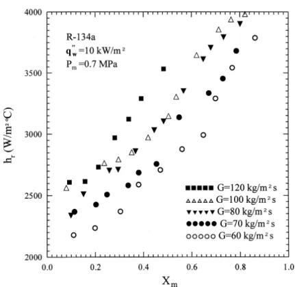
Fig[ 2[ Variations of condensation heat transfer coe.cient with mean vapor quality for various mass ~uxes at Pm 9[6 MPa and
qwý 09 kW:m1[
3[0[ Two phase condensation heat transfer
Figure 2 shows the e}ects of the refrigerant mass ~ux on the measured R!023a condensation heat transfer coe.cient at an average pressure of 9[6 MPa and an average imposed heat ~ux of 09 kW:m1
for the mass ~ux ranging from 59 to 019 kg:m1 s and the mean vapor
quality varying from 9[97 to 9[75[ The mean vapor quality Xm is the average vapor quality in the plate heat
exchanger estimated from Xiand DX[ These data indicate
that at a given mass ~ux the condensation heat transfer coe.cient almost increases linearly with the mean vapor quality of the refrigerant in the PHE[ This increase is rather signi_cant[ For instance\ at 59 kg:m1s the con!
densation heat transfer coe.cient at the quality Xmof
9[7 is about 69) larger than that at 9[0[ This obviously results from the simple fact that at a higher Xmthe liquid
_lm on the surface was thinner and the condensation rate is thus higher[ But a rise in the mass ~ux does not always produce a comparable increase in the condensation heat transfer[ Speci_cally\ the hrvalues for G 019 kg:m
1 s
are the highest except at low qualities\ Xm³ 9[14[ At
G 79 and 099 kg:m1s the h
rvalues di}er only slightly[
They are larger than those for G 59 and 69 kg:m1
s to some degree[ A close inspection of the data in Fig[ 2 reveals that at a given G there exists a sharp rise in the
condensation heat transfer coe.cient at a certain Xm[
For a higher mass ~ux the sharp change appears at a lower vapor quality[ For example\ at G 59 kg:m1s the
change occurs at Xm¼ 9[54 and at G 79 kg:m 1
s the change is at Xm¼ 9[44Ð9[5[ This sharp change in hr is
attributed to the ~ow pattern change[ Speci_cally\ when the vapor quality decreases the vapor ~ow may become laminar instead of being turbulent due to the smaller vapor ~ow rate[
Next\ results are presented to illustrate the e}ects of the average imposed heat ~ux on the condensation heat transfer coe.cient[ Figure 3 shows the R!023a con! densation heat transfer coe.cients at three di}erent heat ~uxes " 09\ 02 and 05 kW:m1# at 9[6 MPa and 59 kg:m1
s[ Note that the quality!averaged condensation heat transfer coe.cients at 02 and 05 kW:m1are respectively
about 5) and 09) larger than that at 09 kW:m1
[ Com! pared with the mass ~ux e}ects shown in Fig[ 2\ the heat ~ux has a smaller e}ect on the condensation heat transfer coe.cient in the high vapor quality region[ Again at a certain Xma sharp rise in hrwith the mean vapor quality
was observed for each heat ~ux[ Note that these large changes in hrappear for Xmaround 9[5 for all three cases[
Then\ the e}ects of the average refrigerant pressure on the R!023a condensation heat transfer are examined[ Figure 4 presents the data for the condensation heat
Fig[ 3[ Variations of condensation heat transfer coe.cient with mean vapor quality for various heat ~uxes at G 59 kg:m1s and
Pm 9[6 MPa[
transfer coe.cient at the heat ~ux of 09 kW:m1and mass
~ux of 59 kg:m1 s for three system pressures of 9[6\
9[7 and 9[8 MPa which respectively correspond to the saturated temperatures of 15[6>C\ 20[2>C and 24[4>C for R!023a[ The results indicate that an increase in the system pressure leads to a slight reduction in the condensation heat transfer[ Speci_cally\ the mean heat transfer coe.cient at 9[8 MPa is about 4 to 09) smaller than that at 9[6 MPa[ This is conjectured to be mainly resulting from a 4[3) reduction in the conductivity of liquid _lm for the R!023a pressure raised from 9[6 to 9[8 MPa[
Finally\ it is necessary to compare the present data for the R!023a condensation heat transfer coe.cient in the plate heat exchanger to those in circular pipes reported in the literature[ Due to the limited availability of the data for pipes with the same ranges of the parameters covered in the present study[ The comparison is only possible for a few cases[ This is illustrated in Fig[ 5\ in which our data are compared with those from Eckels and Pate ð2Ł[ Note that the data from Eckels and Pate are average hrvalues measured in a long pipe of 2[56 m in
length with the vapor quality varying from 9[8 at the pipe inlet to 9[0 at the exit[ The comparison in Fig[ 5 manifests that even at a lower mass ~ux of 099 kg:m1s the R!023a
condensation heat transfer coe.cient for the plate heat
exchanger is about 14) in average higher than that for the circular pipe with the mass ~ux of 029 kg:m1s[
3[1[ Two phase frictional pressure drop
The changes of the frictional pressure drop with the vapor quality and mass ~ux\ as shown in Fig[ 6\ are similar to those for the condensation heat transfer coe.cient in Fig[ 2[ Note that the variation of DPfwith
the vapor quality is much larger than the heat transfer coe.cient[ At G 79 kg:m1s the frictional pressure drop
can be approximately increased by six times for Xmraised
from 9[1 to 9[7[ Figure 7 shows the e}ects of the wall heat ~ux on the frictional pressure drop[ These data indi! cate that some increase in the pressure drop results when the heat ~ux is raised from 09 to 02 kW:m1[ But a further
rise to 05 kW:m1
does not result in a noticeable di}erence in DPf[ Figure 8 manifests the e}ects of the system
pressure on the frictional pressure drop[ Note that the system pressure has a very small e}ect on the frictional pressure drop in the PHE[
3[2[ Correlation equations
To facilitate the use of the plate heat exchanger as a condenser\ correlating equations for the dimensionless
Fig[ 4[ Variations of condensation heat transfer coe.cient with mean vapor quality for various pressures at G 59 kg:m1s and
qwý 09 kW:m1[
condensation heat transfer coe.cient and friction factor based on the present data are provided[ They are Nu hrDh k0 3[007Re9[3 eqPr 0:2 0 "20# and ftpRe 9[3 Bo−9[4
0
pm Pc1
−9[7 83[64Re−9[9356 eq "21#where Pcis the critical pressure of R!023a "3[953 MPa#\
Reeq is the equivalent Reynolds number and Bo is the
boiling number[ Reeqand Bo are de_ned as
Reeq GeqDh m0 "22# Bo qwý Gifg "23# in which Geq G
$
0−Xm¦Xm0
r0 rv1
0:1%
"24#Here Geq was proposed by Akers et al[ ð6Ł and is an
equivalent mass ~ux which is a function of the R!023a mass ~ux\ mean quality and densities at the saturated condition[ Figure 09 shows the comparison of the pro! posed condensation heat transfer correlation to the
present data\ indicating that most of the experimental values are within 204)[ Figure 00 illustrates the com! parison of the proposed correlation for the friction factor to the present data[ It is found that the average deviation is about 02[2) between the ftpcorrelation and the data[
4[ Concluding remarks
An experimental investigation has been conducted in the present study to measure the condensation heat trans! fer coe.cient and pressure drop of R!023a in a plate heat exchanger[ The e}ects of the mass ~ux of R!023a\ average imposed heat ~ux\ system pressure and vapor quality of R!023a on the measured data were examined in detail[ The results show that the condensation heat transfer coe.cient and pressure drop normally increase with the refrigerant mass ~ux[ But the increase in the pressure drop is more signi_cant[ Note that a sharp rise in the heat transfer coe.cient was found with a small increase in the vapor quality during condensation for a lower mass ~ux but not clearly for a higher mass ~ux[ A rise in the average imposed heat ~ux results in slightly better condensation heat transfer accompanying with a larger pressure drop[ Finally\ it was noted that at a higher system pressure the condensation heat transfer coe.cient
Fig[ 5[ Comparison of the present heat transfer data for the plate heat exchanger with those for circular pipe from ð2Ł[
Fig[ 7[ Variations of frictional pressure drop with mean vapor quality for various heat ~uxes at G 59 kg:m1s and P
m 9[6 MPa[
Fig[ 8[ Variations of frictional pressure drop with mean vapor quality for various pressures at G 59 kg:m1s and q
Fig[ 09[ Comparison of the proposed correlation for Nusselt number with the present data[
is slightly lower[ But the e}ects of changing the system pressure on the pressure drop are small[ Correlations were also proposed for the measured heat transfer coe.cients and pressure drops in terms of the Nusselt number and friction factor[
Acknowledgements
The _nancial support of this study by the engineering division of National Science Council of Taiwan\ through contract NSC74!1110!E!998!935 and Dr[ B[C[ Yang|s help during construction of the present experimental facility are greatly appreciated[
References
ð0Ł L[M[ Schlager\ M[B[ Pate\ A[E[ Bergles\ Evaporation and condensation heat transfer and pressure drop in horizontal\ 01[6 mm micro_n tubes with refrigerant 11\ J[ Heat Trans! fer 001 "0889# 0930Ð0936[
ð1Ł L[M[ Schlager\ M[B[ Pate\ A[E[ Bergles\ Heat transfer and pressure drop during evaporation and condensation of R11 in horizontal micro!_n tubes\ Int[ J[ Refrig[ 01 "0878# 5Ð 03[
ð2Ł S[J[ Eckels\ M[B[ Pate\ An experimental comparison of evaporation and condensation heat transfer coe.cients for HFC!023a and CFC!01\ Int[ J[ Refrig[ 03 "0880# 69Ð66[ ð3Ł K[ Torikoshi\ T[ Ebisu\ Evaporation and condensation
heat transfer characteristics of R!023a\ R!21 and a mixture
of R!21:R!023a inside a tube\ ASHRAE Trans[ 88 "0# "0882# 89Ð85[
ð4Ł X[ Liu\ Condensing and evaporating heat transfer and pressure drop characteristics of HFC!023a and HCFC!11\ J[ Heat Transfer 008 "0886# 047Ð052[
ð5Ł L[M[ Chamra\ R[L[ Webb\ Advanced micro!_n tubes for condensation\ Int[ J[ Heat Mass Transfer 28 "0885# 0728Ð 0735[
ð6Ł W[W[ Akers\ H[A[ Dean\ O[ Crosser\ Condensation heat transfer within horizontal tubes\ Chem[ Eng[ Prog[ 43 "09# "0847# 78Ð89[
ð7Ł M[M[ Shah\ A general correlation for heat transfer during _lm condensation inside pipes\ Int[ J[ Heat Mass Transfer 11 "0868# 436Ð445[
ð8Ł R[K[ Shah\ W[W[ Focke\ Plate heat exchangers and their design theory\ in] R[K[ Shah\ E[C[ Subbarao\ R[A[ Mash! elkar "Eds[#\ Heat Transfer Equipment Design\ Hemi! sphere\ Washington\ DC\ 0877\ pp[ 116Ð143[
ð09Ł S[G[ Kandlikar\ R[K[ Shah\ Multipass plate heat exchangers!e}ectiveness!NTU results and guidelines for selecting pass arrangements\ J[ Heat Transfer 000 "0878# 299Ð202[
ð00Ł S[G[ Kandlikar\ R[K[ Shah\ Asymptotic e}ectiveness!NTU formulas for multipass plate heat exchangers\ J[ Heat Transfer 000 "0878# 203Ð210[
ð01Ł E[E[ Wilson\ A basis for traditional design of heat transfer apparatus\ Trans[ ASME 26 "0804# 36Ð69[
ð02Ł R[K[ Shah\ A[S[ Wanniarachchi\ Plate heat exchanger design theory in industry heat exchanger\ in] J[!M[ Buchlin "Ed[#\ Lecture Series\ No[ 0880!93\ Von Karman Institute for Fluid Dynamics\ Belgium\ 0881[
ð03Ł J[G[ Collier\ Convective Boiling and Condensation\ 1nd ed[\ McGraw!Hill\ 0871[
ð04Ł S[J[ Kline\ F[A[ McClintock\ Describing uncertainties in single!sample experiments\ Mech[ Eng[ 64 "0# "0842# 2Ð01[