國立交通大學
資訊科學與工程研究所
碩 士 論 文
以區域為基礎的整數線性規劃軌道繞線
A Novel Zone-Based ILP Track Routing
研究生:林怡君
指導教授:李毅郎 教授
以區域為基礎的整數線性規劃軌道繞線
研究生:林怡君 指導教授:李毅郎 博士
國立交通大學 資訊科學與工程研究所
摘要
軌道繞線是一個位於全域繞線和細部繞線的中間步驟,這個步驟非常適合考慮 deep submicron 相關的議題,例如: 雜訊(crosstalk),臨界區域(critical area), 和金屬密 度(metal density),我們在這裡提出了一個軌道繞線的線性整數規劃的模型,軌道繞線包 含 n 層指派和軌道指派,在 n 層指派法方面上,我們提出了的方法可以達到平均密度,避 開障礙物和保證可繞性。在軌道指派上,藉由更動花費表格(cost table),我們可以盡量減 少線段長度(wire length)和 考慮 deep submicron 相關的議題,在最後我們提出一個平 行化的繞線演算法,這個平行化的方式能夠大量的降低運算時間。實驗結果上我們以金屬 密度作為我們方法的驗證,我們的實驗結果顯示可以降低 9.5%的 Maximal Density 區域和 密度的標準差減少了 3.5%,最後,我們的用 8 顆 Cpu 做平行化減少了約 80%的執行時間.
A Novel Zone-Based ILP Track Routing
Student: Tina-lin Advisor: Dr. Yih-Lang Li Institute of Computer Science and Engineering
National Chiao-Tung University
Abstract
Track routing is an intermediate step between global routing and detailed routing. It is an ideal stage to consider deep submicron (DSM) issues, such as crosstalk, critical area, and density distribution. This paper provides a track routing model via Integer Linear programming (ILP). The proposed layer assignment optimizes routability, balances density distribution and avoids obstacles. In track assignment stage, we adopt extensive cost table to minimize cost for DSM issues and local wire length based on wire segment assignment results. For speeding up, the parallelism algorithm is provided to simultaneously route nets of each panel. Experimental results indicate that the proposed track routing algorithm improves maximal density by 9.5% and density deviation by 3.5% to using detailed router only. In addition, the proposed parallelism algorithm reduces 80% routing time in 8 core processer compared with 1 core system.
Acknowledgement
I am deeply grateful to my advisor, Dr. Yih-Lang Li for his continuous guidance, support, and ardent discussion throughout this research. His useful suggestions help me to complete the thesis. Also I express my sincere appreciation to all classmates in my laboratory for their encouragement and help. Especially I want to thank my senior classmate Ke-Ren Dai for his assistance and direction in this work.
This thesis is dedicated to my parents and my families for their patience, love, encouragement and long expectation.
Contents
摘要... I Abstract ...II Acknowledgement... III Contents ...IV List of Figures ...VI List of Tables ...VII Chapter 1 Introduction... 1 Chapter 2 Routing Model... 3 2.1 Problem Definition ... 4 Chapter 3 Proposed Algorithem... 6 3.1 Overview of the proposed algorithm... 6 3.2 Encoding Track Assignment ... 6 3.3 ILP layer assigment ... 8 3.4 ILP track assigment...11 3.5 Solution space reduction...16 3.6 Parallel algorithm...17 3.7 Refinement ... 18 Chapter 4 Applications ...19 4.1 Metal density...19 4.2 Crosstalk...20 4.3 Critical area ...21 Chapter 5 Experimental Results...22 Chapter 6 Conclusions ...26 Chapter 7 References ...27List of Figures
Figure 1. Routing model... 3
Figure 2. Track, iroutes and panels ... 4
Figure 3. Overview of the proposed algorithm ... 6
Figure 4. Zones ... 7
Figure 5.Density distribution... 7
Figure 6. Layar assigment example 1... 8
Figure 7. Layar assigment example 2... 11
Figure 8. Iroute arrangement example... 13
Figure 9. Independent sets of iroutes... 17
Figure 10.A refinement example. ... 18
List of Tables
Table I. Notations in layer assigment ... 9 Table II. Notations in track assigment ...14 Table III.Notations in applications ...19 Table IV. MCNC benchmark criticuit...24 Table V. Comparision via and wirelength between NEMO and track router + NEMO...24Table VI. Comparision stander deviation and maxminal density in windows between NEMO[16] and Track router + NEMO ...25
Table VII. Comparision stander deviation and maxminal density in windows between L.A[5] and our layer assigment...25
Chapter 1
Introduction
For the technology nodes beyond deep submicron era, interconnect dominates the timing failure, manufacturability, yield and reliability of a system. Approaches for addressing timing issue or coupling noise are proposed in [1–3] by maximizing minimal timing slack and reduced timing violation. Routers considering chemical mechanical polishing (CMP) topography variation control are proposed in [4-5] with balancing wire density to enhance the yield in manufacturability. As for critical area, interconnect optimization for random-defect-related yield is proposed in [6-8], which decreases probability of failure (POF) to avoid yield lose. Many previous works focus on these issues in routing stage. Traditionally, routing consists of global routing and detailed routing. With given obstacles and pins, global routing determinates sub-region (G-cell) paths of each connection in G-cell array, and then detailed routing identifies the layer and physical location of each routing path.
Batterywala et. al [9] proposes track routing preceding detailed routing to reduce complexity of detailed routing. Track routing determines the location of long wire segments, called iroutes, that are extracted from global paths. This stage has several advantages; the first is that routing resources are consumed efficiently because most routes are straight. The second is that track routing in different panels can be routed independently. Thus, track routing natural own high parallelism. Finally, because all iroutes are assigned to tracks together, considering yield and reliability issues, such as crosstalk, metal density and critical area, in track routing is more efficient than in detailed routing. The track
routing algorithms could be classified into two categories. The first category [9] used weighted bipartite graph to model track assignment problem. This category constructs overlap graph (OLG) for iroutes, gets maximum clique in OLG and assigns the iroutes in the maximum clique to tracks by minimal edges weight matching. This step repeats until all iroutes are assigned to tracks or no feasible assignment is found. The second category [2] [3] [8] ordered wire segments first, and then rearranges them to optimal location. .
Existing track routing algorithms are efficient. However bipartite matching based algorithms have weakness as considering interconnection among the same iroute clique, while for the algorithms in [2][8], different iroute orders yield different results and obstacles may degrade assignment quality. This paper has the following characteristics. I. The proposed obstacle-avoiding ILP layer assignment uniformly distributes iroutes to
layers and assures subsequent track assignment can find feasible solution based on the resultant layer assignment.
II. The proposed zone-based ILP track assignment partitioned each panel into zones such that it becomes feasible to encode every assignment as a number. The cost of every assignment is then stored in a cost table, making this approach extensible to optimize other design issues by updating the cost table.
III. The proposed parallel ILP track routing schedules the routing order of each panel to raise CPU utilization on multi-core platform.
The rest of this paper is organized as follows; section II describes problem definitions, section III presents our ILP model for track routing. Section IV is cost metrics construction. Finally, experimental results and conclusion are in Section V .
Chapter 2
Routing Model
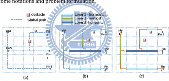
This work adopts the same routing model as in [9]. As shown in Fig. 1, At first, the global routing stage determines the global path of each multi‐pin net. The physical location of long wire segments is then determined by the track routing stage. Finally, a detailed routing stage completes incomplete nets.
While this work focuses on the track routing stage, the subsequent section defines some notations and problem formulation.
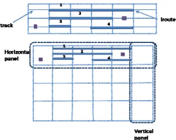
Figure 2. Track, iroutes and panels
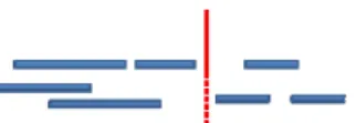
2.1 Problem Definition
Figure 2 illustrates a routing example of 6×4 G-Cell array. A panel comprises serial connected G-Cells in a row or column. An iroute is a net completely passing through at least one G-Cell. Additionally, a track denotes a position where an iroute can be assigned in a panel. A panel contains several tracks with fixed separation between them. An iroute can be assigned to a track if the interval of the iroute in the track is not occupied by other iroutes and existing obstacles.
Track routing contains two problems. The first problem involves assigning iroutes to available layers, while the second one involves determining the physical location of each iroute. The following are the basic formulations for these two problems.
Layer assignment: Given a set of iroutes IR, a set of available layers L, a set of panels P, and a set of existing obstacles in layers O, the layer assignment assigns each iroute of IR to a layer and assure that the resultant layer assignment is assignable in track assignment. Track assignment: Given a panel P, a set of tracks T in P, a set of fixed obstacles O in P, and a set of iroutes IR, the track assignment determines the track position for each iroute
such that any two overlapping iroutes are assigned to different tracks and each assigned iroute does not overlap any existing obstacle.
Chapter 3
The proposed algorithm
3.1 Overview of the proposed algorithm
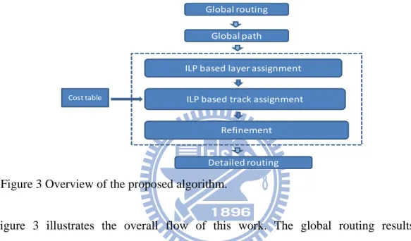
Figure 3 illustrates the overall flow of this work. The global routing results are pre-processed so that all nets are extracted into iroutes and assigned to panels based on their dimensions. After global routing, ILP-based layer assignment determines the proper layer of the iroutes and, then, ILP-based track assignment assigns all iroutes to tracks in each layer. When all iroutes locate the optimal position, a detailed router completes the unfinished routing. The following sections specify the details of each component.
3.2 Encoding Track Assignment
Analyzing the layout entails dividing the whole layout into zones. According to Fig. 4 (a), a vertical line is drawn based on x coordinates of the end points of each iroute, and
Figure 3 Overview of the proposed algorithm.
Global routing Global path ILP based layer assignment ILP based track assignment Refinement Detailed routing Cost table
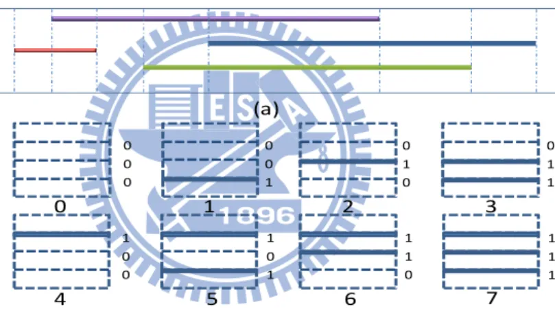
the layout is partitioned into several zones. Importantly, partitioning the region into zones allows a fixed number of iroutes to cross each zone, leading to a finite solution space in each zone. For instance, a 3-track panel contains only 8 combinations as shown in Fig. 4 (b), thus reducing the complexity of estimating the cost of each solution and encoding every track assignment solution as a number. Closely inspecting each zone allows us to analyze the whole layout. For instance, in metal density analysis, the metal density of each zone in Fig. 5 (b) is balanced, but not in Fig. 5 (a). Notably, Z1 and Z3 in Fig.5 (a) have an imbalanced metal density, also leading to imbalanced total metal density. Thus, the whole panel is also balanced when the density of each zone is balanced.
Figure 4 (a) Cut layout to zones; (b) solution number of zone.
0 0 0 0 1 0 0 1 1 0 1 2 3 1 0 0 1 0 1 1 1 0 1 1 1 4 5 6 7 0 0 1 (a) (b)
Figure 5 (a) Non-uniform density distribution; (b) uniform density distribution.
z1 z2 z3 z1 z2 z3
3.3 ILP Layer Assignment
This work develops an ILP based layer assignment to avoid obstacles and place as many iroutes into panels as possible.
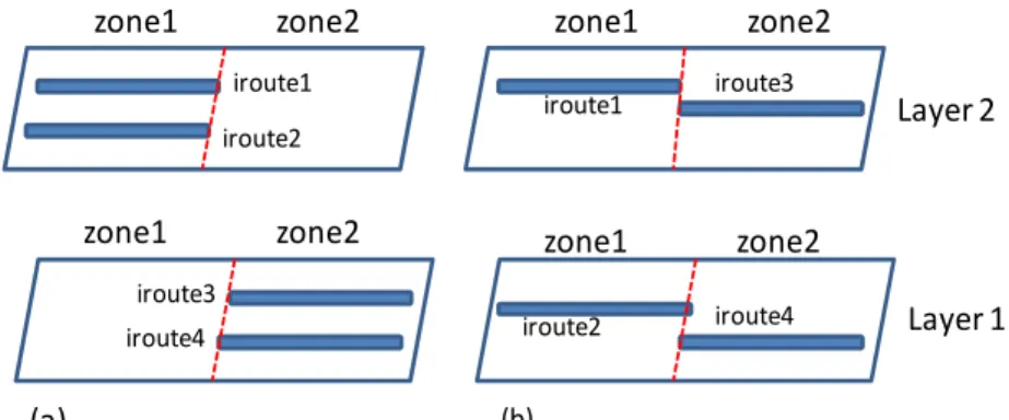
Generally, spreading iroutes to each layer and balancing iroute distribution advances crosstalk, critical area, metal density and routability. Layer assignment here thus focuses on averaging the iroute distribution. According to Fig. 6 (a), a non-uniform iroute distribution would lead to a large variation of iroute number between zones of different layers. However, a balanced iroute layer assignment would lead to a small variation of iroute number among zones, as shown in Fig. 6 (b). Therefore, the optimal iroute arrangement is that with the minimum variation of iroute number among each zone of each layer and, therefore, is used here as the objective function.
Figure 6 (a) Unbalanced iroute distribution layer assignment; (b) balanced iroute distribution layer assignment.
iroute1 Layer 2 Layer 1 (a) (b) iroute2 zone1 zone1 zone2 zone2 zone1 zone2 zone1 zone2 iroute3 iroute4 iroute1 iroute3 iroute2 iroute4
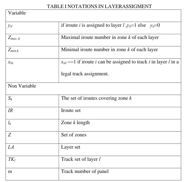
Table 1 lists all notations in the layer assignment. The proposed ILP formulation is described as follows.
TABLEINOTATIONSINLAYERASSIGMENT Variable
yil if iroute i is assigned to layer l ,yil=1 else yil=0
Zmax ,k Maximal iroute number in zone k of each layer
Zmin,k Minimal iroute number in zone k of each layer
xlit xitl ==1 if iroute i can be assigned to track t in layer l in a
legal track assignment. Non Variable
Sk The set of iroutes covering zone k
IR Iroute set
lk Zone k length
Z Set of zones
LA Layer set
TKl Track set of layer l
Constraint (a) stipulates that only one iroute can be assigned to one layer; constraint (b) obtains the maximal iroute number in zone k of each layer; constraint (c) obtains the minimum iroute number in zone k of each layer. Constraint (d) sets yil as 1 if assigning iroute i
to layer l guarantees to find a track to accommodate iroute i in layer l, constraint (e) represents the overlapping constraint to confirm whether if iroutes overlap with each other, thus making it impossible to assign an overlapping iroute to the same track in the same layer; in addition, constraint (f) offers the obstacle constraint to avoid assigning iroute i to track t in layer k if at least one obstacle overlaps iroute i and track t in layer k. Constraints (d), (e), and (f) ensure that at least one track assignment solution is identified. Figure 6 illustrates a simple example of a two layer assignment with three obstacles and two iroutes. l lit il lit l ljt lit tn t lit il k k LA l il k k LA l il LA l il Z k k k k TK t LA l IR i x h LA l IR i y g t track in obstacles has l layer in i iroute if x f j iroute with overlaps i iroute if TK t LA l x x e LA l ir i x y d Z k S i Z y c Z k S i Z y b IR i y a Z Z l
, , ], 1 , 0 [ ) ( , ], 1 , 0 [ ) ( , 0 ) ( , , , 1 ) ( , , ) ( , , ) ( , , ) ( , 1 ) ( ) ) ( * ( : min 1 min, | | 1 max, | | 1 | | 1 min, max,Although considering obstacles complicates the computation in optimization, a layer assignment algorithm not considering obstacles may yield an assignment result that is unroutable in track assignment. Previous works [5] [9] are weak in considering obstacles and sacrificed some qualities to obtain a feasible layer assignment solution. The proposed layer assignment resolves this problem. The layer assignment in [5] may find unfeasible layer assignment solution because it does not consider the problem that some iroutes may be assigned to the wrong layer where there has no space for those iroutes. And in [9], this work first assigns iroutes which have few assignable tracks; this tip limits the solution space. The proposed layer assignment resolves this problem.
3.4 ILP track assignment
This section describes the ILP objective and key concepts first and, then, introduces the proposed ILP model for track assignment.
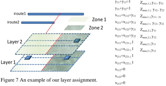
Figure 7 An example of our layer assignment.
Layer 1 iroute1 Layer 2 iroute2 Layer 2 Zone 1 Zone 2 y11+y12=1 y21+y22=1 x111+x112=y11 x211+x212=y12 x121+x122=y21 x221+x222=y22 x111+x121≦1 x112+x122≦1 x211+x221≦1 x212+x222≦1 x112=0 x122=0 x212=0 Zmax,1≧y11+ y21 Zmax,1≧ y12+ y22 Zmin,1≦y11+21 Zmin,1≦ y12+ y22 Zmax,2≧y11 Zmax,2≧y12 Zmin,2≦y11 Zmin,2≦y12
A. Objectives
The ILP objectives in this work are classified into essential and configurable objectives. Wire length minimization is the essential objective in track assignment that influences local wire length used to connect iroute with unconnected components (pins or iroutes). The wire length shortens if the iroute is located close to the unconnected pin or iroute, which should be connected. Assume that unconnected component position is pi, and
the location of iroute i is piri. Wire length cost can then be formulated as | pi -piri |, and can
be used to control the local wire length.
After a layout is partitioned into zones, the number of solutions in a zone in an n-track panel is limited to 2n. Thus, configurable objective can be achieved by constructing the cost table containing each solution cost in an n-track zone for a specific objective, including density distribution, crosstalk or critical area; in addition, it can be accessed by a number ranging from 0 to 2n-1.
Obtaining the cost of each zone involves estimating an index representing the assignment result to access the cost table. The assignment index is obtained by computing assignment matrix. Figure 8(b) depicts the assignment matrix of the zone assignment in Fig. 8(a), where xit equals 1 if iroute i is assigned to track t. In this matrix, the row represents
the assignment of each iroute. Next, the table index of the assignment of a zone, say k, is calculated by first identifying the rows that represent the assignment of iroutes in zone k. Next, all identified rows are summed up to obtain a new row. The new row is regarded as a binary bit sequence that is translated into the index to access the cost table. Consider zone Z3 in Fig. 8(a) as an example, in which iroute 1 and iroute 3 cross Z3. The first row [0 1 0] and the third row [0 0 1] in Fig.8(b) represent the assignments of these two iroutes,
which are then summed up to attain the binary index of Z3; the index is [0 1 1]2=3, then
the cost of Z3 is the value in cost table of index three.
Figure 8. (a) An iroute arrangement example; (b)xijarray represents (a). (a) z1 z2 z3 11 12 13 21 22 23 31 32 33 0 1 0 1 0 0 0 0 1 x x x x x x x x x 2 1 3 (b)
B. ILP Formulation
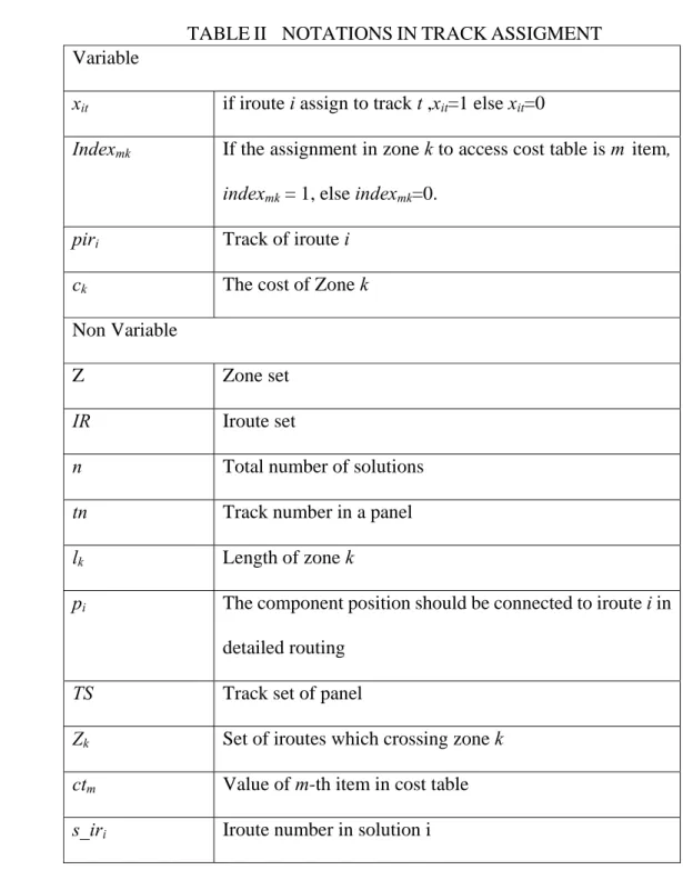
TABLEII NOTATIONSINTRACKASSIGMENT Variable
xit if iroute i assign to track t ,xit=1 else xit=0
Indexmk If the assignment in zone k to access cost table is m item,
indexmk = 1, else indexmk=0.
piri Track of iroute i
ck The cost of Zone k
Non Variable
Z Zone set
IR Iroute set
n Total number of solutions tn Track number in a panel lk Length of zone k
pi The component position should be connected to iroute i in
detailed routing TS Track set of panel
Zk Set of iroutes which crossing zone k
ctm Value of m-th item in cost table
Table 2 lists all notations in the track assignment, and the general ILP formulation is as
follows.
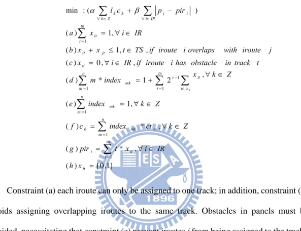
Constraint (a) each iroute can only be assigned to one track; in addition, constraint (b) avoids assigning overlapping iroutes to the same track. Obstacles in panels must be avoided, necessitating that constraint (c) prevent iroutes i from being assigned to the track t if at least one obstacle overlaps with iroute i and track t. Constraint (d) (e) attains the index of the assignment for each zone to access the cost table, while constraint (f) obtains the cost of each zone from the cost table. Constraint (g) identifies the track location of each iroute. With the minimal summation of each zone cost and the cost table, this ILP formulation can optimize a specific objective defined in the cost table.
When using bipartite matching method, the track routers cannot consider the interconnected effect among the same clique of iroutes; because the psychical iroute location in the same clique of OLG could not be determined when the clique of iroutes is
] 1 , 0 [ ) ( , * ) ( , * ) ( , 1 ) ( , 2 1 * ) ( , , 0 ) ( , , 1 ) ( , 1 ) ( ) ( : min 1 1 1 1 1 1 1
it tn t it i n m mk m k n m mk n m tn t i z it t mk it jt it tn t it IR i i i k Z k k x h IR i x t pir g Z k ct index c f Z k index e Z k x index m d t track in obstacle has i iroute if IR i x c j iroute with overlaps i iroute if TS t x x b IR i x a pir p c l k assigned, the effect of other iroutes location in the same clique can not be added to edge weight in bipartite matching graph. However the interconnected effect can be considered by the track routers of this work. Previous works determining iroutes order initially may have optimization order problem, but this work does not have previous defects.
3.5 Solution space reduction
The above ILP formulation may cause time complexity because there are many tracks and iroutes, which may incur millions of variables and constraints; therefore, the
reduction of problem size is needed. A. Redundant solution pruning
As mentioned above, the number of zone solutions is based on track number in panel. But some solutions could be pruned because of the conflict between them. Take an example of zones solution 1 and solution 3, the number of iroute in solution 1 is one, but it is two in solution 3. They couldn’t both exist in the zone solution space at the same time. Therefore, the iroute number covering the zones leads to the impossible solutions which are pruned by modified constraint (d) and the new variables are defined as follows
k m s_ir r_ir 1 1 , 2 1 * ) ( tn t i z it t mk k Z k x index m dB.
Cut independent component
NEW NOTATIONS
s_irk Iroute number in zone k
As show in Fig. 9, the seven iroutes can be divided into two independent sets; the physical iroutes location in a set would not affect other iroutes in another set. By performing ILP with independent set, the problem variables and constrains could be reduced.
C.
Merging zones
The iroute arrangements in those zones are the same, if they have the same iroutes covering them. The ILP formulation could use the same variable to symbolize those zones without sacrificing quality.
D.
Sub-panel
If a layout is partitioned into top-panel and down-panel by modifying layer assignment ILP formulation, iroutes can be assigned by each zone that reduces total variables and constrains.
3.6 Parallel algorithm
This section describes a simple yet efficient parallel routing schedule. Routing order is based on the routing complexity of each panel. Processing complex panels first balances the loading of each CPU, subsequently increasing CPU utilization. The fact that the routing complexity of a panel fully depends on the zone number and iroute number in the panel explains why α|IRp| +β|Zp| is used as the routing priority of panel p, where IRp denotes the
set of iroutes in panel p and Zp represents the set of zones in panel p. The parallel
algorithm constructs a priority queue of panels. When completing its task, a CPU obtains a routing task from the priority queue, this step repeats itself until the queue is empty.
3.7 Refinement
After track assignment stage, some areas in a layout may be recognized as hotspot for our issue according to ILP objective value. Experiments shows that most iroutes in a hotspot area span many G-cells, which limits iroutes arrangement solutions, thus splitting long iroutes and rearranging them would benefit quality.
At this stage, the refinement would repeat until no ILP objective value more than the threshold .Figure 10 shows a simple refinement example, the original iroute arrangement can’t assign any iroute in a lower layer because of long iroutes and obstacles. By splitting those iroutes in hotspots can make it feasible.
Chapter 4
Applications
This section describes the cost table construction for three optimization problem considering wire density, crosstalk, and critical area; table III lists the notations
4.1
Density
Most works use Fixed-Dissection Density Analysis [10] [11] to evaluate density by
an unit area of layout, called windows. The density difference among windows figures
out layout density distribution. Besides, as show in Fig. 4, if each zone density is TABLEIIINOTATIONSINAPPLICATION
Li Length of iroute i
Achip Total area of chip
lij Overlapping length between iroute i and iroute j
Wi Wire i
sij Spacing between Wi andWj
Wmin The minimum wire width in a layer
Smin The minimum wire space in a layer
wi Wire width of wire i
α, ß Constant factor
balanced, the layout density is also balance. Thus, to analyze density distribution by
each zone is reasonable. The cost table construction focuses on each zone, the model can
apply Delaunay Triangulation to evaluate iroutes distribution as in [5]. As Fig. 11 shows,
if the density distribution is balanced, the area difference among triangles is small; but
the density distribution became large if distribution is not uniform. The area difference
between the biggest triangle and smallest triangle was employed by Chen et al. in [5] to
formulate density cost, and can be adopted to construct the cost table for density
distribution for the proposed ILP formulation
4.2 Crosstalk
The simple crosstalk model based on coupling capacitive [2] [12], and the coupling capacitance between Wi and Wj can be defined as:
j i ij c s l j i C . * , (1)Figure 11. A Delaunay Triangulation example; (a) uniform distribution; (b) non-uniform distribution.
Sine each panel is partitioned into zones in this work, the couple capacitance must be accumulated zone by zone.
ij Z z z z c s i j l j i C ) , ( * , (2)
, where Zi,j contains the zones passed by iroutes i and j, lz is the length of zone z, and
) , (i j
sz is the separation between iroute i and iroute j. Thus sum of couple capacitance in each zone is the same as total couple capacitance computed without zone. With constructing couple capacitance for each zone solution, the crosstalk aware cost table can be constructed.
4.2 Critical area
The probability of failure (POF) for the critical area analysis with the defect size distribution is widely used for yield prediction and optimization [13] [14], and formulations of POF for open and short failures are given as follows:
) 2 ( 2 2 min min i i i chip i o i w S w S w A kL POF (3)
)
2
(
2
2 min min ij ij ij chip ij s ijs
W
s
W
s
A
kl
POF
(4)The POF for open defects on Wi is eq. 3 and eq. 4 is the POF for short defects between Wi and Wj. For the total layout, POF can be computed zone by zone, because POF is a linear
function in each iroute arrangement whose sij, Wmin and smin are constant. Thus critical area
Chapter 5
Experimental Results
We implement the proposed track routing algorithm in C++ and use SCIP v10 [15] as our ILP solver. We use NEMO as our detailed router to complete the routing. We take density distribution control as an example to verify the efficiency of the proposed zone-based ILP track routing. The cost metric for density distribution is presented in section IV A. Fixed dissection density analysis strategy [10] [11] verifies results and assumes the window size is 9 um and step size r = 25. Table IV lists the benchmark characteristics of MCNC circuits. Focusing on track routing stage, this work compares with NEMO [16] using the same global routing results. All test cases are run on AMD Opteron 3.0GHz with 48GB memory with 8 cores.
Density distribution
Table VI shows the comparison of routing results between NEMO [16] and our track router with NEMO [16] in MCNC benchmark circuits where Wmax stands for the maximal
density of windows in fixed dissection density analysis, Dev. gives its standard deviation, Imp. W denotes the reduction rate of the maximal density window and Imp. D represents the reduction rate of the standard deviation in window’s density. By comparing each layer of each case, the proposed track routers yields 3.5% standard deviations reduction of the wire distribution and 9.5% reduction in maximal density in windows. And the average increase of vias and wirelength is 2% as Table V shows.
Figure 12. Parallel time of s38584 in 8 cores. 0 50 100 150 200 250 300 350 400 1 2 3 4 5 6 7 8 core s38584 1 340.416 2 172.367 3 116.826 4 91.4622 5 76.0968 6 62.9747 7 55.6549 8 51.7478
core
secs
ParallelWe also implement parallel algorithm on a 8-core CPU server, and use OpenMP[17] as our parallel library. Compared with the sequential track routing, multi-threaded ILP track routing reduces the runtime by 80.66% on average. Figure 9 shows the execution time of s38584 with different cores. The execution time of s38584 is 350s with one core and 51s with 8 cores. Experimental results show that the proposed parallel algorithm has good scalability.
Layer assignment
To compare layer assignment quality, we implement layer assignment in [5]. Table VII shows the comparison of routing results between Layer assigment[5]+our tack assignment+NEMO [16] and our track router with NEMO [16] in MCNC benchmark circuits. The meaning of Wmax, Dev, Imp. W and Imp. D are the same as Table VI. The rip
up iroutes stand for the number of iroutes which have no assignable track because of obstacles. Experimental results show that track routing using our layer assignment have
higher completion rate than the work in [5]. Because the comparison focuses on layer assignment, we only represent the comparison in horizontal layers. Compared Wmax and
Dev. with [5], the proposed track routers yield 5.28% standard deviations reduction of the wire distribution and 6.25% reduction in maximal density in windows.
Via Wire length
NEMO TA+ NEMO NEMO TA+ NEMO
S9234 4728 4884 56092 57517 S5378 5752 6072 75509 77308 S13207 12573 12597 178351 181638 S15850 14679 15129 223361 228004 S38417 37611 37740 489195 501576 S38584 50501 50724 671845 685409 Ratio 1 1.022 1 1.021
TABLE V VIAANDWIRELENGTH
circuit Size(um2) Layer net pin GC size(um2) GC
s9234 404*222 3 1486 4260 7.214*7.258 57*32 s5378 435*239 3 1694 4818 7.25*7.242 61*34 s13207 660*365 3 3784 10776 7.253*7.299 91*51 s15850 705*389 3 4472 12793 7.254*7.212 98*54 s38417 1144*619 3 11309 32344 7.24 *7.283 159*85 s38584 1295*672 3 14754 42931 7.212*7.225 236*94
L-A[5] +OUR T-A result+NEMO[16]
Our track routing + NEMO[16] result
circuit Layer1 Layer3 Layer1 Layer3 Wmax Dev Wmax Dev
Rip-up
iroute Wmax Dev Imp.W Imp.D Wmax Dev Imp.M Imp.D Rip-up iroute s9234 0.321 0.0561 0.329 0.0517 135 0.311 0.0550 2.9% 0.7% 0.274 0.0468 16.65% 9.4% 0 s5378 0.320 0.0562 0.321 0.0645 217 0.312 0.0565 2.62% -0.7% 0.313 0.0567 2.40% 12.06% 0 s13207 0.332 0.0541 0.382 0.0602 377 0.320 0.0517 3.47% 4.38% 0.349 0.0555 8.63% 7.73% 0 s15850 0.367 0.0543 0.443 0.0757 509 0.336 0.0512 8.36% 5.66% 0.395 0.068 10.8% 9.4% 0 s38417 0.347 0.0605 0.471 0.0525 998 0.390 0.0618 -12.3% -2.23% 0.373 0.0477 20.36% 9.10% 0 s38584 0.384 0.0618 0.442 0.0672 1412 0.362 0.0581 2.83% 6.09% 0.405 0.0659 8.31% 1.70% 1 average 1.31% 2.31% 11.20% 8.42% NEMO[16] result Track routing + NEMO [16] result
circuit Layer1 Layer2 Layer3 Layer1 Layer2 Layer3
Wmax Dev. Wmax Dev. Wmax Dev. Wmax Dev. Imp.W Imp.D Wmax Dev. Imp.W Imp.D Wmax Dev. Imp.M Imp.D s9234 0.329 0.0568 0.433 0.0761 0.301 0.0458 0.311 0.0550 5.4% 1.91% 0.393 0.0735 3.36% 9.1% 0.274 0.0468 10.46% -2.21% s5378 0.369 0.0602 0.420 0.0727 0.321 0.0595 0.312 0.0565 15.48% 6.05% 0.377 0.0678 10.23% 6.8% 0.313 0.0567 2.40% 4.67% s13207 0.361 0.0557 0.449 0.0780 0.4 0.0596 0.320 0.0517 11.36% 7.16% 0.403 0.0741 10.24% 4.94% 0.349 0.0555 12.67% 6.78% s15850 0.348 0.0550 0.452 0.0755 0.444 0.0744 0.336 0.0512 3.24% 6.87% 0.401 0.0710 11.23% 5.99% 0.395 0.068 10.99% 7.75% s38417 0.385 0.0631 0.482 0.0836 0.388 0.0483 0.390 0.0618 -1.13% 1.93% 0.426 0.0827 11.44% 1.13% 0.373 0.0477 3.96% 1.23% s38584 0.413 0.0582 0.481 0.0812 0.500 0.0662 0.362 0.0581 12.20% 0.03% 0.423 0.0803 11.96% 1.12% 0.405 0.0659 19.32% 0.5% average 7.73% 3.99% 10.7% 3.89% 9.97% 3.12%
TABLE VIICOMPARISON OF ROUTING RESULTS AMONG [5] AND OUR ROUTER IN
LAYERASSIGMENT
Chapter 6
Conclusions
In this paper, we present a zone-based ILP track routing. The obstacle-avoiding layer assignment guarantees the routability in track assignment for every generated layer assignment result, and balance density distribution. The proposed ILP track assignment can easily adopt different cost tables to efficiently optimize different yield issues. Finally, we propose a simple parallel algorithm to route the nets of each panel simultaneously, significantly reducing run time. Experimental results reveal that the proposed track routing algorithm can achieve better density control than using detailed router only. Furthermore, the proposed parallel scheduling algorithm has good scalability on multi-core platform.
Chapter 7
References
[1] J. Hu and S. S. Sapatnekar. "A timing-constrained simultaneous global routing algorithm." in Proceedings of Computer-Aided Design of Integrated Circuits and Systems, IEEE Transactions, pages 1025- 1036, 2002
[2] Y.-N. Chang, Y.-L. Li, W.-T. Lin, and W.-N. Cheng, "Non-slicing floorplanning-based crosstalk reduction on gridless track assignment for a gridless routing system with fast pseudo-tile extraction," in Proceedings of the 2008 international symposium on Physical design, Pages 134-141, 2008
[3] D. Wu, J. Hu, M. Zhao, and R. Mahapatra, "Timing driven track routing considering coupling capacitance," in Proceedings of the 2005 Asia and South Pacific Design Automation Conference, Pages 1156 - 1159, 2005.
[4] M. Cho, D. Z. Pan, H. Xiang, and R. Puri, "Wire density driven global routing for CMP variation and timing," in Proceedings of the 2006 IEEE/ACM international conference on Computer-aided design, Pages: 487 - 492, 2006.
[5] H.-Y. Chen, S.-J. Chou, S.-L. Wang, and Y.-W. Chang, "Novel wire density driven full-chip routing for CMP variation control," in Proceedings of the 2007 IEEE/ACM international conference on Computer-aided design, Pages 831-838, 2007.
[6] D. Muller, "Optimizing Yield in Global Routing," in Proceedings of the 2006 IEEE/ACM international conference on Computer-aided design, Pages: 480 - 486, 2006.
[7] S.-Y. Kuo, "YOR: A yield-optimizing routing algorithm by minimizingcritical areas and vias," in Proceedings of Computer-Aided Design of Integrated Circuits and Systems, Pages:1303 - 1311, 1993
[8] C. Minsik, X. Hua, R. Puri, and D. Z. Pan, "TROY: track router with yield-driven wire planning," in Proceedings of the 44th annual Design Automation Conference, Pages: 55 - 58, 2007.
[9] S. Batterywala, N. Shenoy, W. Nicholls, and H. Zhou, "Track assignment: a desirable intermediate step between global routing and detailed routing," in Proceedings of IEEE International Conference on Computer Aided Design, page 59–66, 2002.
[10] A. B. Kahng, G. Robins, A. Singh, and A. Zelikovsky, "Filling algorithms and analyses for layout density control," in Proceedings of Computer-Aided Design of Integrated Circuits and Systems, pages 445 - 462, April 1999.
[11] Y. Chen, A. B. Kahng, G. Robins, and A. Zelikovsky, "Monte-Carlo Algorithms for Layout Density Control," in Proceedings of the 2000 conference on Asia South Pacific design automation, pages 523-528, January 2000
[12] H. Zhou, D. F. Wong, "Global Routing with Crosstalk Constraints," in Proceedings of the 35th annual Design Automation Conference, Pages: 374 - 377, 1998
[13] F. Lee, A. Ikeuchi, Y. Tsukiboshi, and T. Ban, "Critical Area Optimizations Improve IC Yields," on line EE Times, 2006.
[14] T. Iizuka, M. Ikeda, and K. Asada, "Exact Wiring Fault Minimization via Comprehensive Layout Synthesis for CMOS Logic Cells," in Proc. International Symposium on Quality Electronic Design, 2004
[16] Y.-L Li, X.-Y Chen, and Z.-D Lin, "NEMO: A New Implicit Connection Graph-based Gridless Router with Multi-layer Planes and Pseudo-tile Propagation," in Proceedings of IEEE Transactions on Computer-Aided Design of Integrated Circuits and Systems, page 705-718,2007.