行政院國家科學委員會專題研究計畫 成果報告
虛擬私有網路閘道 Layer2/Layer3 安全通訊協定之研究與設
計(2/2)
計畫類別: 個別型計畫
計畫編號: NSC91-2213-E-009-041-
執行期間: 91 年 08 月 01 日至 92 年 07 月 31 日
執行單位: 國立交通大學資訊工程學系
計畫主持人: 謝續平
報告類型: 完整報告
報告附件: 出席國際會議研究心得報告及發表論文
處理方式: 本計畫可公開查詢
中 華 民 國 92 年 10 月 28 日
行政院國家科學委員會專題研究計畫成果報告
虛擬私有網路閘道 Layer 2/Layer3 安全通訊協定之研究與設計
The Study and Design of VPN Layer2/Layer3 Secure Communication
Protocols(2/2)
計畫編號:NSC 91-2213-E-009 -041-
執行期限: 91 年 8 月 1 日至 92 年 7 月 31 日
全程計劃: 91 年 8 月 1 日至 92 年 7 月 31 日
主持人:謝續平 教授 國立交通大學資訊工程學系
中文摘要 隨著網際網路通訊的安全性的日益需求,IPsec 閘道己成為在保護整個子網路上的一個極有 效率的方式,但最為人所垢病的,就在於 IPsec 閘道上的處理速度,這也影響著整個受保護網 路的處理能力,因此,為了加速整個 IPSec 閘 道的強度,叢集式的技術是非常有效的方法, 但因為叢集式的關鍵則在於一個於中央控管 分派工作的技術,因此在本年度計劃我們將提 出一個以叢集式架構為基楚的 IPsec 閘道機制 來整合虛擬私有網路上-VPN,進而增進其安 全強度,可擴展性及提昇 VPN 整體效能。 關鍵詞 虛擬私有網路,叢集式,IPsec,Queuing theory AbstractDue to the increasing demand of secure communications over the Internet, IPsec gateway becomes one of the popular methods to provide security services to all clients in a protected subnet. The processing speed of an IPsec gateway is critical to the overall network throughput. To accelerate processing speed and improve reliability, cluster technology was inherently applied to the design of a modern IPsec gateway. Traditional dispatcher/master-based cluster technique must have a centralized dispatcher to handle all incoming and outgoing messages. In this project, we proposed a clustered-based architecture for IPsec gateway to integrate VPN, and increase drastically the overall system strength and performance.
Keywords:
Security gateway, VPN, IPsec, Cluster, load balancing
1. Introduction
With the rapid advance in communication technologies, many emerging Internet applications have accentuated the need for security mechanism in the Internet. To relieve software engineers of developing proprietary secure protocols, IP security protocol (IPsec) suites [1] [2] [3] provide security services such as authentication, integrity and confidentiality. One of the most popular applications of IPsec is the construction of Virtual Private Network (VPN), which allow two subnets to build secure connections over the public Internet.
However, the traffic handled by the gateway also becomes heavier than the early period with the rapid growth of data transmission technologies. To be capable of dealing out the increasing load, cluster technologies are adopted on the design of IPsec gateways.
In a clustered IPsec gateway, packets are distributed to different devices to achieve load balance among them. In such an environment, how to synchronize SA information between these machines is the most important thing we concerned.
With the purpose of increasing the throughput of VPN gateways, some vendors also implement their VPN gateway products by using cluster technologies, such as Cisco and NetScreen [4] [5]. However, most of them use the session-based load-balancing scheme for their implementation. To provide better load balancing for clustered IPsec gateway, we also apply packet-based traffic dispatching schemes for clustered IPsec gateway.
To implement a high-speed IPsec gateway, clustering technology has been adopted to parallelize the IPsec encryption/decryption procedures. Traditional cluster technology means a dispatcher and lots of slave nodes. Typically, the dispatcher would handle all
incoming and outgoing messages, and it would dispatch time-consuming operations to slave nodes. But in IPsec environments, it’s difficult to design a dispatcher-based cluster using an existing commercial Load Balancer. Because IPsec SPI sequence number assigning is an important issue for IPsec’s anti-replay mechanism. As a result, design a dispatcher to fit IPsec environment is needed for clustered IPsec gateway.
Traditional clustering technique provides the ability to perform parallel processing of CPUs that reside in discrete devices. In this kind of cluster, a dispatcher is responsible for all of the operations performed throughout the cluster; only time-consuming calculations are distributed to other slaves. This technology could cause single point of failure straightforwardly if dispatcher was crashed. And if computation power of the dispatcher cannot be capable to deal all incoming packets, it would become the bottleneck.
New cluster technology, such as [9] and [10], could offer truly load-balance and fault-tolerance. It can also have lower latency for packet transmit. But it could only be suitable for operations that have no co-relationship, such as different http request. While processing related requests, this cluster technique fails or needs more operation for synchronization. In other words, it lacks some mechanisms for operations that need real-time synchronization, e.g., SPI sequence number assigning. Hierarchical architecture Flat architecture Synchronizat
ion Easy Hard Transfer
latency High Low Fault-toleran
ce Bad Good Scalability High Medium High Possible
bottleneck Dispatcher Not obviously Table 1-1. Comparison for two cluster technologies
Since there is a dispatcher/master in hierarchical architecture, it may be ease of control, management, and synchronization, but it also need some mechanism to inform slaves some information. And because the existence of dispatcher, it could become the bottleneck and could cause single point of failure easily. On the contrary, synchronization in flat architecture
is more difficult. Since all nodes would receive all packets, it would cause more CPU overhead to process them, but it could have better fault-tolerance, (Microsoft claims their NLB has (N-1)-way failover in a cluster with N hosts). More over, filtering unwanted packets is faster than examining, rewriting, and resending packets, so, flat architecture would have low latency than hierarchical one.
We propose a load balancing approach to implement a high speed IPsec gateway. The design is simplified by using the new clustering technology architecture. With layer-two multicast technique, all cluster nodes received all packets. To evenly distribute traffic to cluster nodes, there was a filter driver running on all the cluster nodes. This driver would also keep track of all incoming packets and synchronize IPsec SA SPI.
In the next section, we present a flat clustered IPsec gateway architecture and estimate its overhead. Section 3 discusses the dispatch schemes, session-based vs. packet-based and round-robin vs. shortest-queue-first. In Section 4, we present the performance of this proposed architecture and some comparison with others. Finally, Section 5 gives a conclusion and our future work.
2. Proposed Flat Clustered IPsec Gateway
In the proposed flat architecture, IPsec protocol is executed in a clustered architecture. Microsoft suggests using layer-two broadcast or multicast to simultaneously distribute incoming network traffic to all cluster nodes in environment using a switch instead of a hub. We also try to use layer-2 multicast MAC address for our IPsec gateway, but thus it causes other problems.
In Linux, if an interface wants to receive packets whose destination address is a multicast MAC address without adding a multicast group, it should enable the promiscuous mode or all-multicast mode. Or packets addressed to a multicast MAC address would be dropped in Linux kernel. Enable the promiscuous mode or all-multicast mode would make NIC to receive all network packets and cause kernel to process all of them. Since not all of the received packets are addressed to this cluster, it causes more overhead for kernel. Packets sent by cluster nodes would be sent back to all of them if their destination MAC addresses were multicast ones. This is the condition we do not want to expect.
In a clustered IPsec environment, how to assign the proper SPI sequence number and let this value synchronized in all nodes are the most important things we concerned. Sending messages between cluster nodes for every incoming packet, such as Nokia IP clustering, seems cost too many operations and may not catch up the speed in high speed environment. In this section, we introduce the overall
architecture and estimate the possible overhead as well as the operations of its components.
2.1 System Architecture
We adopt de-centralized, clustered architecture with packet-based load balancing approach for system architecture. Thus, there is only one major component, a set of cluster nodes, in
Figure 2-1. Architecture for Proposed IPsec Gateway
proposed clustered IPsec gateway.
Each node in this cluster is capable of processing all incoming packets, either forwarding them or encapsulating/extracting them in/out IPsec tunnel. Figure 2-1 shows a pair of proposed clustered IPsec gateways and the traffic flows. All of the cluster nodes are connected via gigabit Ethernet switch. And they must share two IP addresses in order to deliver packets directly to the destination node (one for outgoing traffic and one for incoming). To improve performance, each cluster node has two network interface cards. Two Ethernet switches are used to separate the connections between the router and local intranet, so that the distributed IPsec gateway can act as a virtual router to the local network. By intercepting ARP request to router, this IPsec gateway can act as a default router of the subnet transparently to control all the traffic across it.
To illustrate how packets flow through the clustered IPsec gateway, we assume that the packet is originated from the left subnet and its destination is on the right one. First, packet coming from the left side local network is delivered to the IPsec gateway using layer-two multicast. All of the cluster nodes would receive this packet and locate the correspondent
SA first.
SA specifies sequence number information as well as the algorithm and key used to generate or validate the integrity check value (ICV). Since every node in this cluster would receive all and the same count of packets, all of them would assign the same value of sequence number for the current packet. Then some dispatching scheme would be calculated and find only one node of them to continue processing it. Other cluster nodes would update IPsec SA database only and then drop current packet. The encrypted-packet would then directly forward to the router of local area network by the node processing it. The router forwards this packet to the right side IPsec gateway according to its routing table.
Upon receipt of this packet, this encrypted-packet would also be received by all the cluster nodes in the right side IPsec gateway. All of them would check its IPsec ICV value and update the IPsec anti-replay windows. But only one of them would decrypt this packet and forwards it to the ultimate destination by deploying dispatching schemes. Other nodes would drop it after anti-replay window updates. Since all of the cluster nodes, either in sender side or receiver side, would receive all the
Cipher Text
packets, the problem of run-time assigning of IPsec sequence number is preserved.
Figure 2-2 shows some processing steps for an original IPsec Gateway; and Figure 2-3 shows the modified processing steps for our IPsec Gateway, which after adding a filter driver to filter out unwanted packets within IPsec processing step.
In the proposed architecture, the computation power of the IPsec gateway scales up with the number of cluster nodes increasing in the system. Adding a new node can be achieved by setting the same IP addresses with other nodes. And other nodes would know there is new node added by the heartbeat messages sending by the new node. Then the default host would organize new dispatching scheme and deploy it the all the nodes by adding some options of heartbeat messages. Moreover, since there is no modification to the standard IPsec protocol, compatibility with other IPsec systems is preserved.
2.2 Synchronization Between Cluster Nodes
Each node in this cluster would have its own unique host-identity. They would elect one node as default host to interact ARP with clients and handle other interactive operations. This default host must communicate with other IPsec hosts/gateways/devices to perform key exchange protocols, e.g., IKE [8]. It is also responsible for sending heartbeat messages to all of the cluster nodes and then receiving all acknowledgements from them. Other cluster nodes would expect receiving heartbeat messages from default host and then trying to reply them. If they did not receiving any heartbeat messages from default host in a period of time. They would assume that the default
host was down, and would try to re-elect one node as a new default host
There are some problems while performing encryption/authentication key exchange. For instance, how to reduce packet lost while key renewing and prevent lost of synchronization between two end devices. Some solutions have been propounded to solve these problems in IETF IPsec working group. Our goals are trying to ease our proposed IPsec gateway as a simple IPsec device, not cluster ones.
We propose a simple scheme to reduce our proposed IPsec gateway as a simple IPsec device. For IKE packets which directly addressed to the IPsec gateway itself, all the cluster nodes would accept them, but only the default host would try to response them. As a result, the entire cluster nodes would have the new encryption/authentication key at the same time. Thus, problems of key renewing are reduced as a simple IPsec device would face up.
2.3 Overhead Estimate and Service Rate Prediction
Since the entire cluster nodes would receive all the packets through the IPsec gateway, but only one of them would really process them. It obviously causes some overhead for nodes that are not responsible for processing them.
Take IPsec outbound traffic as example, Figure 2-4 shows some steps for a machine to process IPsec tunneling packets.
Assume it would take Q(s) units of time for one machine from receiving a s-byte packet, passing it to Physical layer, MAC layer, IP layer, updating IPsec SA database, and finally our filter driver, which decide drop this packet or not (as darker region in Figure 2-4). Assume the following steps — encapsulate and encrypt the current packet, and pass it back to physical medium – would take another R(s) unit of time. As a result, processing one s-byte packet would take R(s)+Q(s) unit of time.
If each cluster node can process P units per second, the maximum number of s-byte packets one node can process within one second,
C1,s, is P/( R(s)+Q(s) ). Therefore, while
feeding s-byte packets, the maximum number for units one node can process within one second,
C1,s, is
)
(
)
(
s
Q
s
R
P
+
and the maximumservice rate measured in bytes/second is
IPsec Processing IPsec Processing Physical layer MAC layer IP layer Physical layer MAC layer IP layer Physical layer MAC layer IP layer Physical layer MAC layer IP layer Physical layer MAC layer IP layer Physical layer MAC layer IP layer
Figure 2-2. Processing steps for an IPsec Gateway
Physical layer MAC layer IP layer Physical layer MAC layer IP layer Physical layer MAC layer IP layer Physical layer MAC layer IP layer Physical layer MAC layer IP layer Physical layer MAC layer IP layer IPsec Processing IPsec Processing IPsec Processing filter
)
(
)
(
, 1s
Q
s
R
s
P
s+
×
=
µ
Assume we have n cluster nodes(s) and use round-robin filtering algorithm. While receiving n s-byte packets, each node would receiving all of them but processing only one of them. We can just simplify it to that it would take R(s)+nQ(s) unit of time to process one packet. As a result, while feeding s-byte packets, the maximum number of units a cluster node can process within one second, Cn,s, is
)
(
)
(
s
nQ
s
R
P
+
.Then we have the maximum service rate of n cluster nodes(s) measured in bytes/second is
)
(
)
(
,s
nQ
s
R
s
P
n
s n+
×
×
=
µ
2.4 Modeling by Queuing theory
Since our architecture is several parallel servers sharing a single limited queue. And while incoming packets have Poisson (i.e. ``random'') arrivals and exponential service times, we can model our service queue as a
(M/M/c):(GD/K/∞) queuing model [12] [13] [14]
[15].
Thus, whatever how many cluster nodes we have, the arrival rate λn equals λ. Because
each node would get more overhead while more packets coming, we have service rate
µ
n=
c
µ
, where c < n. And we have the traffic intensityρ = [(λ)/(µ)]; the proportion of time the system
is idle 0
!
c
P
c
P
n c n n=
−ρ
, where( )
1 1 1 0 01
!
1
!
− + − − =
−
−
+
=
∑
c
c
c
n
P
c K c c n nρ
ρ
ρ
ρ
.Finally, we have the effective arrival rate into the system
λ
eff=
λ
(
1
−
P
n)
.3. Dispatch Schemes
This section discussed the dispatch schemes we used in the filter driver; we simply divide them to two kinds – session-based vs. packet-based and round-robin vs. shortest-queue-first. Session-based and packet-based dispatching schemes are used to locate which cluster node should process the coming packets according to which session it belongs or just ignoring session information. While new session or new packet comes, round-robin and shortest-queue-first dispatch schemes are used to find which cluster node should responsible for it.
3.1 Session-based versus Packet-based
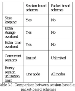
The granularity used for load balancing will dominate the performance of the clustered system. Current load balancing systems can be divided into two classes: session-based and packet-based. In session-based load balancing, it will result in unbalanced load sharing if the loads of sessions are lopsided. In this case, the cluster nodes serving heavy-load sessions may be overwhelmed while other nodes remain idle. Moreover, throughput of any single session is limited by the computation power of a cluster node.
The granularity used for load balancing will dominate the performance of the clustered system. Current load balancing systems can be divided into two classes: session-based and packet-based. In session-based load balancing, it will result in unbalanced load sharing if the loads of sessions are lopsided. In this case, the cluster nodes serving heavy-load sessions may be overwhelmed while other nodes remain idle. Moreover, throughput of any single session is limited by the computation power of a cluster node.
In contrast, packet-based load balancing systems can distribute packets to any one of the cluster nodes that is capable of processing it. Thus, packet-based load balancing share load Steps for all incoming packets
Other steps for packets the current node is responsible for
Physical layer MAC layer IP layer Physical layer MAC layer IP layer Physical layer MAC layer IP layer Physical layer MAC layer IP layer Physical layer MAC layer IP layer Physical layer MAC layer IP layer IPsec Processing IPsec Processing IPsec Processing filter
more evenly than session-based systems. In the worse case, the clustered system will still be fully utilized even there is only a single network session. According to RFC2451 [16], each IPsec packet can be encrypted/decrypted independently. This flexibility enables the cluster nodes to processing packets autonomously without considering the chaining relationships.
Another serious problem in session-based systems is that no one knows which session an encrypted packet belongs before decrypt it in IPsec inbound gateway. In receiver side, find a node using other schemes rather than session-based scheme is needed. This denotes that session-based schemes can only be adopted in IPsec outbound traffic. Table 3-1 lists some comparisons between these two schemes. Since packet-based schemes have more pros, thus, we prefer to use packet-based scheme to dispatch traffic. But session-based scheme is also tested in our experiments.
Session-based schemes Packet-based schemes State keeping Yes No Extra storage overhead Yes No Extra time overhead Yes No Concurrent
sessions limited Unlimited Bursty
session utilization limit
One node All nodes Table 3-1. Comparison between session-based and
packet-based schemes
3.2 Round-Robin versus Shortest-Queue-First
In both packet-based and session-based schemes, while new packet or new session comes, what fashion to deploy is another point. Round-Robin (RR) scheme is the simplest one, but when different size packets come, another sort of unbalance would come into sight. Shortest-Queue-First (SQF) scheme is the best schemes in some way. Since every cluster node in our architecture will receive all coming packets, so how to get the load or queue length of every other node is not the issue. But SQF would cause more overhead to calculate which the shortest queue is then RR fashion. We’ve tested both RR and SQF fashions in our experiments.
4. Performance Measurement
Since the performance of many single machines and products can catch up the wire speed of Fast Ethernet. And migrating to high-speed environment is the trend in few years. It’s meaningless and out of fashion to test cluster technologies in 100 Mbps environment this time. Consequently, we choose Gigabit Ethernet as our testing environment [17] [18] [19]. Although Princeton University has proved that compression improves performance when encryption is employed in high-speed environment [20], but our main purpose is to test the scalability and try to prove it. So, IPComp [21] is not used in our testing.
The test bed is six machines with 1 AMD XP1800+ CPU, 256 MB RAM, 2 Intel PRO/1000 XT Gigabit NIC running on 66 MHz/64-bit PCI bus, and 1 SafeNet SafeXcel 140-PCI encryption acceleration card. One 3Com SuperStack 3 4900 12-port Gigabit Switch with one 4-port 1000BASE-TX module is configured as 2 or 4 VLANs for testing. The operating system of these machines is Red Hat Linux 7.2 with 2.4.18 kernel. FreeS/WAN 1.97 is used as implementation of IPsec on this clustered IPsec gateway. And Smartbits-200 of Spirent Communications with 2 GX-1420B Gigabit modules acts as the Traffic Analyzer.
4.1 Fixed-Size Traffic
The larger packet sizes, the less overhead caused by IP stack. Thus, the overhead would be different by feeding packets with different size. So, we first generate a set of fixed-size streams from Smartbits-200 to test our IPsec gateway in this ideal testing environment. Because we only have six machines for testing, three of them must act as sender side gateway and the other three machines must act as receiver side gateway.
After testing from one node to three nodes, we found that the performance of this testing was bounded by the sender side. It denotes that the performance was bounded by encryption operations; the speed of decryption can always catch up encryption. So we change our settings to that our entire six machines act as sender side IPsec gateway. We test its performance after they encrypt the packets then deliver they to the router.
Table 4-1 shows performance results using simple round-robin dispatching scheme. We gained these results by setting Smartbits-200 to send timed-burst packets in specified Databits/sec for 30 seconds. If no packet lost, we assume our IPsec gateway can handle such traffic. The performance was measured by the Databits/sec, which we configured in
SmartWindows, after subtracting 14-byte Ethernet header.
4.2 Real Traffic
In the following experiments, throughput of packet-based scheme and session-based scheme are evaluated respectively using real traffic which collected from campus backbone router. The characteristic of the traffic figured as follows: Total 1,328,780,468 bytes in 1,118,665 packets, 18,229 sessions. Average 1187.8 bytes per packet (standard division = 524.623). Average 72615.0 bytes per session (standard division = 460311.287). We only collect the IP header of these packets and then regenerate them using SmartBits-200 as the data rate we want. In both session-based and packet-based schemes, sessions and packets are assigned to cluster nodes in RR fashion and SQF fashion. The throughput of each dispatching scheme is presented in Table 4-2
5. Conclusion
In this project, we proposed a flat clustered scheme for implementing a high speed IPsec gateway and conclude a formula to estimate overhead in this architecture. According to our methods, the performance of IPsec gateway can
be easily scaled up by increasing number of cluster nodes. In our analysis, while the overhead is significant small compared with a machines computation power, it can scale up almost linearly.
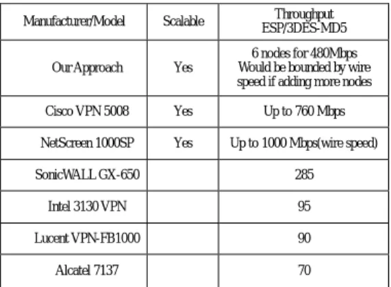
Two companion traffic-dispatch schemes are also presented in this report. As experiment results show, packet-based dispatching scheme provides better load balancing capability. On the other hand, session-based dispatching schemes are not effective to implement an IPsec gateway using cluster architecture. Moreover, total experiment equipments cost less than 5% of Cisco VPN 5008, which is a Cisco VPN gateway product that can achieve to 760 Mbps. Table 5-1shows some comparison with commercial products.
At this moment, our flat architecture would be bounded by the Gigabit Ethernet wire speed (AH mode). Since the processing time of 2*s-size packet would not probably take two times than S-size packet, we would try to reduce the granularity to “load-based”. We believe that trying to figure out Q(s) and R(s) for different-size packets would be helpful for more balanced dispatch.
6. Reference
[1] S. Kent and R. Atkinson, “Security Architecture for the Internet Protocol,” RFC 2401, Nov. 1998.
[2] S. Kent and R. Atkinson, “IP Authentication Header,” RFC 2402, Nov. 1998.
[3] S. Kent and R. Atkinson, “IP Encapsulating Security Payload (ESP),” RFC 2406, Nov. 1998.
[4] Cisco Systems, Inc., “Cisco VPN 5000
Series Concentrators,”
http://www.cisco.com/univercd/cc/td/doc/pc at/vp5000.htm
[5] NetScreen Technologies, Inc., “NetScreen-1000,” Number of cluster nodes Packet-based Round-Robin (Mbps) Packet-based SQF (Mbps) Session-based Round-Robin (Mbps) Session-based SQF (Mbps) 1 83.4 83.4 83.4 83.4 2 161.7 161.7 154.5 161.6 3 235.3 235.3 185.9 230.3 4 304.7 304.6 220.0 284.0 5 370.1 370.1 253.4 323.1 6 431.8 432.0 311.0 362.2
Table 4-2. Throughput using real traffic
ESP/3DES-MD5 ESP/DES-MD5 AH/MD5 Number of cluster nodes 512 bytes/frame (Mbps) 1024 bytes/frame (Mbps) 1446 bytes/frame (Mbps) 1446 bytes/frame (Mbps) 1446 bytes/frame (Mbps) 1 47.2 72.4 87.2 265.2 366.6 2 93.3 141.3 172.1 503.5 686.8 3 138.1 207.1 253.7 716.3 969.9 4 182.3 269.2 333.2 913.9 974.4 5 223.7 329.6 405.3 974.4 974.4 6 265.5 387.9 480.1 974.4 974.4
Table 4-1. Throughput for fixed-size traffic
Manufacturer/Model Scalable Throughput ESP/3DES-MD5 Our Approach Yes
6 nodes for 480Mbps Would be bounded by wire speed if adding more nodes Cisco VPN 5008 Yes Up to 760 Mbps NetScreen 1000SP Yes Up to 1000 Mbps(wire speed) SonicWALL GX-650 285
Intel 3130 VPN 95 Lucent VPN-FB1000 90 Alcatel 7137 70
http://www.netscreen.com/products/systems. html#ns1000
[6] K. Hamzeh, G. Pall, W. Verthein, J. Taarud, W. Little, and G. Zorn, “Point-to-Point Tunneling Protocol (PPTP),” RFC 2637, July 1999.
[7] W. Townsley, A. Valencia, A. Rubens, G. Pall, G. Zorn, and B. Palter, ”Layer-Two Tunneling Protocol (L2TP),” RFC 2661, Aug. 1999.
[8] D. Harkins and D. Carrel, “The Internet Key Exchange (IKE),” RFC 2409, Nov. 1998 [9] Microsoft Corporation, “Network Load
Balancing Technical Overview”,
http://www.microsoft.com/windows2000/tec hinfo/howitworks/cluster/nlb.asp, Jan. 2000. [10] Nokia Corporation, IP Clustering
Technology white paper,
http://www.nokia.com/vpn/pdf/ip_clustering .pdf, Feb. 2000.
[11] Joo-Kok Ng, “A Packet-based Load Balancing Approach for High-speed Clustered IPsec Gateway,” M.S. Thesis, NCTU, June 2001.
[12] Robert B. Cooper, Introduction to Queueing
Theory, Macmillan, 1972.
[13] F. S. Hillier and G. J. Lieberman,
Introduction to Operations Research,
McGraw-Hill, 5th edition, 1990.
[14] H. A. Taha, Operations Research: An
Introduction, Macmillan, 5th edition, 1992.
[15] W. L. Winston, Operations Research,
Applications and Algorithms, Duxbury Press,
3rd edition, 1994.
[16] R. Pereira and R. Adams, “The ESP CBC-Mode Cipher Algorithms,” RFC 2451, Nov. 1998.
[17] Mitchell Loeb, Andrew Rindos, William Holland, and Steven Woolet, “Gigabit Ethernet PCI Adapter Performance," IEEE Network Magazine, vol. 15, No. 2, pp. 42-47, March/April 2001.
[18] Paul A. Farrell and Hong Ong, “Communication Performance over a Gigabit Ethernet Network,” Proceedings the IEEE 2000 International Performance, Computing, and Communications Conference, pp. 181-189, Feb. 2000.
[19] Aamir Shaikh and Kenneth J. Christensen, “Traffic Characteristics of Bulk Data Transfer using TCP/IP over Gigabit Ethernet,” Proceedings the IEEE 2001 International Performance, Computing, and Communications Conference, pp. 103-111, April 2001.
[20] John P. McGregor and Ruby B. Lee, “Performance Impact of Data Compression on Virtual Private Network Transactions,” Proceedings of the 25th IEEE Conference on Local Computer Networks, pp. 500-510,
Nov. 2000.
[21] A. Shacham, R. Monsour, R. Pereira and M. Thomas, “IP Payload Compression Protocol (IPComp),” RFC 2393, Dec. 1998.
[22] L. Aversa and A. Bestavros, “Load Balancing a Cluster of Web Servers Using Distributed Packet Rewriting,” Proceedings the IEEE 2000 International Performance, Computing, and Communications Conference, pp. 24-29, Feb. 2000.
[23] Z. Cao, Z. Wang, E.Zegura, “Performance of Hashing-Based Schemes for Internet Load Balancing,” IEEE INFOCOM 2000, vol. 1, pp. 332-341, March 2000.