行政院國家科學委員會專題研究計畫 成果報告
下世代服務型機器人快速工作定義和全自主執行技術--子 計畫五:服務型機器人之定位導航與派遣
研究成果報告(精簡版)
計 畫 類 別 : 整合型
計 畫 編 號 : NSC 99-2221-E-011-100-
執 行 期 間 : 99 年 08 月 01 日至 100 年 07 月 31 日 執 行 單 位 : 國立臺灣科技大學機械工程系
計 畫 主 持 人 : 李維楨 共 同 主 持 人 : 郭重顯
計畫參與人員: 碩士班研究生-兼任助理人員:蔡淙偉 碩士班研究生-兼任助理人員:周鴻鈞
報 告 附 件 : 出席國際會議研究心得報告及發表論文
處 理 方 式 : 本計畫涉及專利或其他智慧財產權,2 年後可公開查詢
中 華 民 國 100 年 09 月 23 日
行政院國家科學委員會補助專題研究計畫成果報告
下世代服務型機器人快速工作定義和全自主執行技術 -- 子計畫五:服務型機器人之定位導航與派遣
計畫類別:□個別型計畫 ■整合型計畫 計畫編號:NSC 99-2221-E-011-100
執行期間:99 年 08 月 01 日至 100 年 07 月 31 日
計畫主持人:李維楨 計畫共同主持人:郭重顯
計畫參與人員:蔡淙偉、周鴻鈞 (研究生)
執行單位:國立台灣科技大學機械工程系
中 華 民 國 1 0 0 年 9 月 2 2 日
行政院國家科學委員會專題研究計畫成果報告
下世代服務型機器人快速工作定義和全自主執行技術-- 子計畫五:服務型機器人之定位導航與派遣
Rapid Job Definition and Autonomous Execution Systems for Next Generation Service Robots – Project 5: Localization,
Navigation, and Dispatch of a Service Robot
計 畫 編 號:NSC 99-2221-E-011-100
執 行 期 限:99 年 08 月 01 日至 100 年 07 月 31 日 主 持 人:李維楨 國立台灣科技大學機械工程系 共 同 主 持 人:郭重顯 國立台灣科技大學電機工程系 計畫參與人員:蔡淙偉 國立台灣科技大學機械工程系,
周博鈞 國立台灣科技大學電機工程系
一、中文摘要
本計畫為整合型計畫之子計畫,為三年期 計畫之第一年計畫。本計畫之研究目的有二,
其一為建構方位感測器以協助服務型機器人 偵測其自我方向的改變。本研究的創新處在於 將傳統的指南車之差速齒輪機構用來做為此 平台的方位感測器。此感測器包含齒輪組及一 個光學編碼器,較常見的於兩個輪子上各裝置 一個編碼器在成本上較低。和機器人上常用的 電子羅盤比較,使用指南車的優點為其不像羅 盤易受週遭 導磁性 物 品或馬達電 磁場所干 擾。經由實驗證實,此感測器可有效偵測平台 在行進間之角度變化。我們可利用此資訊使平 台行沿一直線運動,或控制平台任意移動。
本計畫之第二個目的為發展一立體視覺 系統以做為定位之用,如此機器人可以在短時 間內移動至指定位置並立即執行物件操作任 務。目前在工廠進行作業的機器人如 RGV(軌 道式無人搬運車)或 AGV(無軌道式無人搬運
車),並無完全自主的行走能力,且須於活動 路線架設軌道,或於地面下埋置磁條進行導 航。此一缺陷除了使得工作地點必須進行複雜 的施工後才能讓機器人進行作業,機器人在活 動上亦無法進行較有彈性及效率之路線規劃。
本計畫為突破此一傳統工作機器人活動 限制,除了進行硬體平台之設計,亦建立演算 法,使用立體視覺進行機器人自主定位。一般 使用 CCD 攝影機所擷取到的影像特徵與實際 影像特徵會有相當的差距,其原因在於安裝時 之位置誤差、CCD 攝影機之鏡頭與 CCD 感測 模組之品質不一致所導致,因此將立體視覺成 像公式在直接運用到立體視覺定位時會產生 偏差。為了解決此一缺陷,此計畫使用一基於 類神經網路之多層感知機(multi-layer per- ception, MLP),建構出 CCD 立體視覺定位模 型以解決在影像特徵擷取上的不一致性之問 題。於本研究中,我們使用了二台 320 × 240 像素的網路攝影機。實驗結果顯示,以此基於 類神經網路之立體視覺系統,在 1000 mm 的
矩離之誤差為 80 mm ,而在 200 mm 的矩離 之誤差為 25 mm。當物體越近時,定位誤差也 越小,故最終此立體視覺系統可準確地將機器 人導航至目標位置。
關鍵詞:移動平台、指南車、立體視覺、視覺 定位、類神經網路
Abstract
The objective of this research was twofold.
First was to develop an orientation sensor to help the service robot platform detect the change of its orientation. An innovative idea of using the old south-pointing chariot on the platform was realized. This sensor based on the south-pointing chariot is cost effective, and free from the electromagnetic interference. The ex- perimental results showed that the sensor can be employed to detect the change of the orientation of the mobile platform. The information pro- vided by the south-pointing chariot can be used to control the platform to move along a straight line or in any desired pattern.
The second objective was to implement a ste- reoscopic vision based positioning system. The vision positioning system is composed of two web cameras. These two cameras are not neces- sary to be placed in parallel. Their orientations can be arranged according to practical consider- ations. In order to deal with the unknown orien- tation relationships of the two cameras, a super- vised neural network model was constructed to identify the spatial coordinates relative to the camera system. The camera resolution is 320 × 240 pixels with 60 frames per second. With this resolution, the positioning error of a spatial marker is within 25 mm in a 200 mm measure- ment range and 80 mm in a 1000 mm measure- ment range. The vision positioning system can guide the robot to approach the target from a long distance. The closer the robot moves to the
target, the less error the vision system will have.
So eventually the robot with the vision posi- tioning system can navigate to the target accu- rately.
Keywords: mobile platform, south-pointing chariot, stereoscopic visions, visual position- ing, neural networks.
二、文獻回顧
一般偵測移動平台的方位會使用輪軸上 的編碼器、電子羅盤及陀螺儀為主。移動平台 可藉由編碼器回授,計算各輪所行走的距離來 估測平台方位,但路面不平造成移動時的打 滑,將可能導致方位計算錯誤。陀螺儀[1]可 感測平台旋轉時的角速度,透過對時間的積分 可間接得到角度參數,但電子式的陀螺儀因溫 度等原因造成零值漂移的問題,將可能產生角 度誤差的累積。電子羅盤[2]則是經偵測地磁 來感測方向,但在羅盤附近有金屬、電線及馬 達等具有磁場或導磁的干擾物時,其角度有偵 測錯誤的可能。故本實驗使用指南車之差速齒 輪及編碼器製作出可應用在移動平台上做為 估測角度的感測器。指南車的發展已有上千年 的歷史,根據史書上記載,指南車曾使用於戰 爭中,做為方向辨識的工具。然自羅盤發明 後,指南車的用途轉為教育及娛樂用。例如,
Hsieh 等人[3]使用行星齒輪製作出八種不同 的指南車,而 Yan 等人[4]也使用拓樸學來分 析指南車。由文獻中未見有使用指南車來做為 機器人定位之用。
而視覺定位系統[5–7]為定位系統發展的新 趨勢。立體視覺[8,9]則是使用兩台攝影機以擷 取目標位置的技術。傳統做法此兩台攝影機必 須平行擺放以使用光學路徑之幾何關係計算 出目標位置 [10,11]。然而,有時因擺放時的 誤差,或是攝影機本身鏡頭的差異,會導致計 算值與實際量測值之間有較大的誤差。因此,
大部份的立體視覺系統所使用的攝影機都是 高品質的攝影機。本研究採用一般之網路攝影
機建構立體視覺系統,以類神經網路加以訓練 以達到精密定位之能力。
三、方位感測器設計及實驗結果
本研究應用指南車傳動的特性搭配編碼 器所設計的新型方位感測器。使用的好處在於 一般差動式平台至少需裝有兩顆編碼器才能 測得平台旋轉的角度,而指南車模組使用齒輪 傳動只需一顆編碼器,即可得到平台旋轉的角 度。但指南車模組在實際使用上目前只能偵測 角度旋轉,並無法測得平台行走的距離,所以 本模組在應用上,可使用在清潔機器人上輔助 其偵測旋轉角度,因為清潔機器人在使用上並 不需要知道行走多少距離。
3.1 指南車模組製作
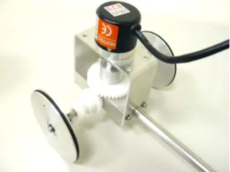
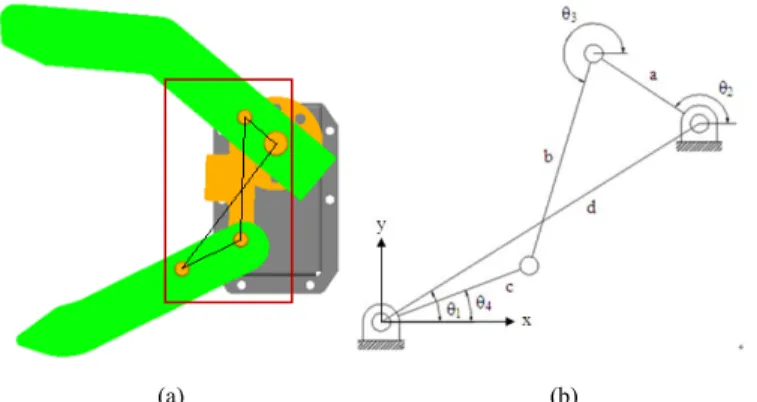
為改善輪軸上編碼器、電子羅盤及陀螺儀 在方位偵測上使用的問題,我們應用指南車機 構傳動的原理,配合編碼器設計一個新型的方 位感測器。本研究中使用 Nuttall[12]型的指南 車做為製作參考,原因為其製作起來的高度較 低,較適合放在平台之下使用,如圖一(a)所 示。圖一(b)為指南車的設計架構圖。
(a)
(b)
圖一:(a)Nuttall 型指南車[12];(b)Nuttall 型指 南車架構圖
本實驗為讓中間輸出桿的旋轉角度等於 指南車旋轉一圈的角度,其設計規格如下:齒 數 N5為 N9的兩倍,車寬長度為車輪直徑的兩 倍。零件的參數規格如表一及表二所示。經由 上述的規格設計,再使用連軸器與編碼器做連 接,即可完成指南車模組的製作,如圖三所 示。
表一:指南車機構設計規格
item specification width of south pointing chariot 120 mm
diameter of wheel 60 mm
表二:齒論設計規格
number of gear (Ni)
module pitch di- ameter
number of teeth i = 1、2、3、7、
8、9
0.8 16 20
i = 4、6 1 20 20
i = 5 1 40 40
圖三:指南車模組實體圖
本研究所設計的指南車模組規格,最小解 析度為 0.25 度,輸出格式為 AB 相。本研究 並使用 Robot-Electronics 所開發的三軸電子羅 盤 CMPS09 測量平台方位以和本研究所開發 之感測器做比較。
3.2 差動式平台模組製作
為測試指南車模組角度輸出的功能,我們 製作了一差動式移動平台,並將指南車模組裝 在平台之下,其中指南車模組被分為從動與主 動式兩種模式,如圖四及圖五所示。
圖四:差動式平台模組(從動式)
圖五:差動式平台模組(主動式)
兩種擺放的差異如下:指南車為從動模式 時,代表指南車模組的輪子並不能主動移動,
而是經由平台運動而帶動的。此情況下平台同 時具有五顆輪子接觸地面,如此可能造成移動 的過程中輪子有打滑的情況發生,導致指南車 模組測量錯誤。指南車為主動模式時,指南車 將與平台共用一組輪子,即代表馬達驅動輪子 旋轉運動時,可同時帶動指南車的齒輪傳動。
而主動模式下平台只有三顆輪子,可避免輪子 在移動過程中未接觸地面的狀況。
3.3 實驗結果與討論
實驗分為三個部分,第一部分為分別對指 南車機構與電子羅盤做角度測量的測試。第二 部分為移動平台搭配指南車模組在直線行走 中所測的方位角度,並與電子羅盤做比較。第 三部分則是移動平台使用指南車模組的移動 性能測試。
3.3.1 指南車機構及電子羅盤角度測試
第一部分的實驗為指南車機構的角度測 試。本研究設計的指南車在固定其中一輪時,
齒輪 9 的角速度為齒輪 5 的四倍,即代表輪子
旋轉四圈等於輸出桿旋轉 360 度,實驗將分別 紀錄每轉一圈的角度量。
測試方法如下:使用一塊鋁擠型卡住其中 一輪,另一輪使用連軸器與步進馬達相連接,
如圖六所示。紀錄左右輪子各旋轉四圈之編碼 器輸出數值,再將其換算成角度。
圖六:測試平台架構圖
指南車模組左右輪各旋轉四圈之編碼器 測量的角度偏差值,其平均最大的誤差約在正 負 1.5 度以內。因指南車使用齒輪做為傳動機 構,齒輪本身齒隙的問題,會造成每次輪子旋 轉到定點時,產生微小的角度差異。可經由將 兩輪固定,轉動中間連軸器觀察背隙造成的讀 數問題,此誤差大約有正負 1.5 度,方法如圖 七所示。而此實驗的結果,將可提高後續實驗 的可信度。
圖七:齒隙測試示意圖
實 驗 的 另 一 部 分 為 電 子 羅 盤 的 角 度 測 試,測試方法使用 AutoCAD 繪製一個圓,每 隔 30 度繪製一條線,如圖八(a)所示。使用電 子羅盤板子的左下側板邊做為基準,如圖八(b) 所示,測試羅盤每隔 30 度所量測的角度。
(a) (b)
圖八 (a) AutoCAD 繪製測試圓;(b)羅盤基 準圖
實驗結果角度誤差量最大為 1.3 度。因為 實驗為手動操作,在基準定位上並不是很精 確,但實驗結果足以確認羅盤的量測準確度。
3.3.2 移動平台直線行走測試
此實驗將比較指南車模組與電子羅盤在 平台行走所測量到的角度差異。測試分兩部 分,第一是用軌道限制平台行走的方向,比較 兩者測量角度的差異,並在實驗的過程中分為 開啟與關閉馬達兩種情況。藉此觀察電子羅盤 是否受到馬達或周邊電路的電磁場影響,實驗 的方式如圖九所示,軌道長度為 1 m。第二部 分則是讓平台在室內有擺設物品的房間及無 物品擺設的走廊行走 4 m,觀察指南車模組是 否可輔助平台保持在預設的路徑上,實驗路徑 如圖十所示。
(a) (b)
圖九:(a)平台行走軌道;(b)平台與軌道貼齊 示意圖
(a) (b)
圖十:(a)室內行走路徑;(b)走廊行走路徑
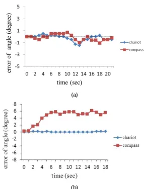
第一部分的實驗結果如圖十一及圖十二 所示,實驗分別對馬達開啟與關閉的情況測試 四次,數據的表現方式是以平台行走的方向做 為基準,觀察電子羅盤與指南車模組所測量的 角度偏差。
圖十一:移動平台直線行走(伺服馬達關閉)
圖十二:移動平台直線行走(伺服馬達開啟)
由圖十一及圖十二的數據顯示,當馬達電 源開啟時,電子羅盤會受到馬達電源的電磁影 響,導致量測的角度與指南車模組所測量到的 角度差異大約 6 度左右。代表電子羅盤在使用 上需注意周圍磁場干擾。
另一部分實驗的結果如圖十三至圖十六 所示,行走到預設定點時與預設路徑之距離偏 差如表三所示。
圖十三:室內行走(主動模式)
圖十四:走廊行走(主動模式)
圖十五:室內行走(從動模式)
圖十六:走廊行走(從動模式)
表三:平台移動到定點距離之偏差量
active passive
maximum offset(mm)
room 65 490 corridor 70 590 由圖十三至圖十六顯示,指南車模組在直 線運動時,不論是主動模式或從動模式,室內 或室外,其變動量均很少,不超過 3 度。而電 子羅盤所測量到的角度變化,在室內使用時不 論是主動模式或從動模式,其最大變異量約 15 度。在室外時從動模式的最大變異約 5 度,
主動模式最大變異亦有約 15 度。表示電子羅 盤在室內外使用時,易受到環境中的導磁性物
品的影響,導致測量失真。另外從表三中的數 據顯示,使用以從動的方式驅動指南車模組 時,不論在室內或走廊,其距離的偏差量都大 於 490 mm 以上。原因為在移動平台行進間,
指南車的輪子未確實與地面接觸,導致指南車 模組讀取錯誤的角度。所以圖十五及圖十六 中,指南車模組所測的角度值雖約保持在正負 3 度以內,但是實際上指南車模組並未讀取到 正確的角度。而平台以主動的方式驅動指南車 模組時,室內及走廊的最大偏差距離大約 70 mm,並且角度的偏差量可保持在正負 3 度以 內。故指南車模組在使用上,主動式模組因為 只使用三顆輪子來驅動,可避免輪子不碰地的 問題。
3.3.3 移動平台移動性能測試
此實驗是讓移動平台應用指南車模組行 走預設的路徑型態,其中包含直線行走與旋轉 平台方位,測試指南車模組是否能讓平台保持 行走在預設的路徑上型態。實驗測試方法如 下:平台前端裝有一顆極限開關,做為碰撞牆 壁時觸發平台旋轉的信號。當開關被觸發時,
平台先退後一小段距離,順時針旋轉 90 度,
沿著牆壁行走一段距離,再順時針旋轉 90 度。下一次碰撞時,則改為逆時針旋轉 90 度,
依此方式不斷循環。測試路徑示意圖如圖十七 所示,其中圖十七(a)為指南車模組在主動模 式下行走的路徑,圖十七(b)則是在指南車模 組在被動模式下行走的路徑,實際測試圖如圖 十八所示。
(a) (b)
圖十七:(a)Z 字形路徑(主動模式);(b) Z 字形 路徑(被動模式)
(a)
(b)
圖十八:(a)Z 字形行走測試圖(主動模式);(b)Z 字形行走測試圖(從動模式)
如圖十八所示,指南車模組不論是以被動 或主動的方式驅動,皆可以輔助移動平台保持 在預設的路徑上及做為旋轉角度的判別。但從 圖十八(b)中發現,以從動方式驅動的指南車 模組行走的路徑較短,原因為平台之下有五顆 輪子,在行走的過程中會有輪子與地面無法接 觸的問題,導致指南車模組無法正確判斷旋轉 的角度。最後尋得一個位置,可讓平台使用從 動式模組行走出預設的路徑,藉此說明從動式 指南車模組雖可輔助平台行走 Z 字形路徑,
但實驗地點 需選擇 在 一個較平的 地面做測 試,才能確保指南車模組能正確執行其功能。
而以主動方式驅動的指南車模組,無輪子與地 面碰觸的問題。因控制器是設定平台行走方位 偏離正負 1 度時,控制左右輪速度去調整平台 方位至正負 1 度內。而當指南車模組讀取角度 是在 0 至正負 1 度之間時,平台隨著移動距離
的增長,將行走斜線的路徑直到角度偏離預設 值,才能夠導正平台行進方向,示意圖如圖十 九所示。其中實線代表理想路徑,虛線代表平 台行走實際路徑。
圖十九:平台使用主動式指南車模組之實際行 走路徑
四、立體視覺定位方法與結果
4.1 實驗架設
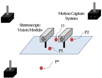
立體視覺定位模型之類神經網路模型如 圖二十,其實驗架設如圖二十一,攝影機取像 頻率 30 FPS,解析度 320 × 240。攝影機鏡 頭相距 80 mm,直視前方。實驗使用動作擷取 系統(phase space motion capture)取得目標點 P*在空間中之實際位置,同時記錄該點在立體 視覺中兩攝影機之影像位置,在設定工作範圍 1 公尺內任意移動 P*之位置,記錄 1000 筆資 料提供立體視覺系統校正。
立體視覺系統
左邊CCD攝影機 影像特徵點
右邊CCD攝影機 影像特徵點
類神經網路MLP 立體視覺定位模型
之深度(Z)特徵點 訓練樣本
圖二十:立體視覺類神經網路模型
圖二十二所示為安裝於機器人上的二部 攝影機,圖 二十三 所 示為裝於天 花板上的 motion capture 攝影機,圖二十四所示裝置於 機器人干台上的三個 LED marker。此三個 marker 即為圖二十一中用來決定視覺座標系 的三點 P1、P2 以及 O 點。此三點為立體視覺 平面之參考,其立體視覺座標系如式(1)所 示。
1 2 1 2
1 2 1 2
, ,
OP OP OP OP
X Y Z
OP OP OP OP
= = = ×
× uuuv uuuv uuuv uuuv
v v v
uuuv uuuv uuuv uuuv (1)
則OPuuuuv*
在該座標系之投影量如式(2)。
* * *
, , .
x=OPuuuuv⋅X yv =OP Y zuuuuv⋅v =OP Zuuuuv⋅v (2)
P*
P1
P2 O
Stereo visual system
Phase space motion capture
圖二十一:立體視覺校正實驗架設
圖二十二:攝影機安裝於機器人平台上
圖二十三:Motion Capture 攝影機架設
圖二十四:Motion capture 之 LED marker 擺置 4.2 類神經網路架構
立體視覺系統之校正是使用倒傳遞類神 經 網 路 ( back-propagation neural network, BPN)。倒傳遞類神經網路屬於監督式學習網 路,是類神經網路中運用相當廣泛的方式,其 架 構 可 分 為 輸 入 層 ( input layer)、 隱藏層
(hidden layer)以及輸出層(output layer),
其訓練資料包含輸入之數值與目標值,藉由網 路訓練學習規則,用以解決線性或非線性之問 題,類神經網路架構如圖二十五。
h
Inputs First layer Second layer N‐th layer Outputs
Input layer Hidden layer Output layer
圖二十五:倒傳遞類神經網路架構
其輸入為目標點 P*在影像之位置,輸出 為OPuuuuv*
在視覺系統座標系之投影量 x, y, z,圖 二十六為實驗之流程圖。
from motion capture
from stereo visual system O (x, y, z) P1 (x, y, z) P2 (x, y, z) P* (x, y, z) * 1000
(unit mm)
Camera 1 (px1, py1) Camera 2 (px2, py2) (unit pixel)
the coordinate of visual system
the scalar project of OP* onto X, Y and Z
* 1000 px1 py1 px2 py2
ANN BPN
X’
Y’
Z’
由動作擷取系統取得點O, P1, P2和P*在空間中之位置
記錄P*在視覺系統之 影像位置
計算P*在視覺系統座 標之位置
由倒傳遞類神經網路
校正立體視覺系統 驗證校正結果
圖二十六:實驗流程圖
在取得的 1000 筆資料中使用 600 筆作為 類神經網路訓練的資料,400 筆為最後驗證之 依據。
4.3 類神經網路訓練
在類神經網路訓練中使用 MATLAB 之 Neural Network Toolbox 工具,如圖二十七所 示,開啟類神經網路工具箱 nntool 後,接著進 行類神經網路的參數設定,包含名稱設定、網 路設定、訓練方法、隱藏層數目設定以及每一 層的神經元數目。完成類神經網路的建立後,
在進行訓練演算法的參數設定,包含訓練次 數、學習率,設定完成後即可進行訓練,如圖 二十八、圖二十九。由此透過類神經網路校正 立體視覺系統,建立立體視覺定位模型。
圖二十七:圖形使用者介面 nntool 的主視窗畫 面
類神經網路工具箱中,倒傳遞網路的權重 值和偏權值一旦被初始化後,網路即準備好可 用來訓練。此訓練過程需要適當的網路行為,
即網路輸入和目標輸出當作範例數據資料 集。在訓練過程中,網路權重值和偏權值被疊 代調整來使網路性能函數極小化。前饋網路的 內定性能函數是均方誤差 MSE,就是在網路 輸出和目標輸出之間平方誤差的平均。引用類 神經網路工具箱中 TRAIN 函數來訓練網路,
這些 TRAIN 函數大致又分為啟發式、數值最 佳化兩種演算技巧。
名稱設定
網路設定
設定層數
設定神 經元數目
圖二十八:類神經網路設定
圖二十九:訓練參數設定
使用啟發式的技巧,是由分析標準最陡坡 演算法而發展出來的,包含指令 TRAINGDA 及 TRAINRP。使用標準的數值最佳化的技 巧,目前發展出來的演算法分類出使用累積誤 差校正法的 TRAINGD(累積誤差校正法)、
TRAINGDA(適應性學習累積誤差校正法)、 TRAINGDM(衝量累積誤差校正法 );使用 共軛梯度法的 TRAINCGF(Fletcher-Reeves 共軛梯度法)、TRAINCGP(Polak-Ribiére 共 軛梯度法)、TRAINCGB(Powell-Beale 共軛 梯度法)、TRAINSCG(Scaled 共軛梯度法);
使 用 矩 陣 法 的 TRAINBFG ( BFGS qua- si-Newton 矩 陣 法 ) 、 TRAINCLM
(Levenberg-Marquardt 矩陣法)。
4.4 類神經網路之立體視覺校正實驗
類神經網路訓練對於 200 mm 以內與 200
mm-100 mm 分別提出不同之類神經網路架 構,200 mm 以內採用之類神經網路參數設定 為:
z Network Type: Feed-forward backprop z Training function: TRAINLM
z Adaption learning function: LEARNGDM z Number of layers: 3
z Properties of layer 1
Number of neurons: 5
Transfer function: TANSIG z Properties of layer 2
Number of neurons: 5
Transfer function: PURELIN z Properties of layer 3
Transfer function: PURELIN 類神經網路架構如圖三十所示:
圖三十:類神經網路架構圖
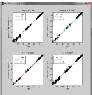
圖三十一為訓練、驗證和測試之誤差績效 衡量分析,圖三十二為訓練、驗證和測試之迴 歸分析結果,圖三十三為驗證立體視覺模型校 正之結果。
圖三十一:訓練、驗證和測試之誤差績效衡量 分析
圖三十二:訓練、驗證和測試之迴歸分析結果
圖三十三:驗證立體視覺模型校正之結果
200 mm-1000 mm 之類神經網路參數設 定為:
z Network Type: Feed-forward backprop z Training function: TRAINLM
z Adaption learning function: LEARNGDM z Number of layers: 3
z Properties of layer 1
Number of neurons: 10
Transfer function: TANSIG z Properties of layer 2
Number of neurons: 10
Transfer function: PURELIN z Properties of layer 3
Transfer function: PURELIN 類神經網路架構如圖三十四所示,
圖三十四:類神經網路架構圖
圖三十五為訓練、驗證和測試之誤差績效 衡量分析,圖三十六為訓練、驗證和測試之迴 歸分析結果,圖三十七為驗證立體視覺模型校 正之結果。
圖三十五:訓練、驗證和測試之誤差績效衡量 分析
圖三十六:訓練、驗證和測試之迴歸分析結果
圖三十七:驗證立體視覺模型校正之結果
五、結論
本研究成功地開發了一方位感測器,其基 於指南車搭配編碼器做為機器人平台旋轉角 度的估測,為一數千年來中華民族的偉大發明 發展出新的具實用性的應用。此感測器不受電 磁場或導磁性物質的干擾,且製作成本低。由 直線行走的實驗中,從動式模組的輪子可能會 因地面不平,使輪子無法有效著地導致測量錯 誤,而主動式模組則無輪子與地面碰觸的問 題。經由實驗數據顯示,主動式指南車模組可 輔助平台在走廊及室內行走 4 m 的距離後,角 度偏差量保持在正負 3 度以內,並與預設路徑 之偏差量約為 70 mm,而從動式指南車模組則 使平台與預設路徑之偏差量約為 590 mm。此 感測器可應用於清潔機器人以提昇其工作效 率。
在以視覺定位方面,攝影機之鏡頭可能由 於感光模組品質不一或者在安裝時之位置誤 差無法進行完美之取像,因此一般立體視覺成 像公式在直接運用到立體視覺定位時會產生 誤差。為了解決此一缺陷,此計畫使用一基於 類神經網路之多層感知機,建構出立體視覺定 位模型以解決在影像特徵擷取上的不一致性 之問題,影響立體視覺之精確。
本實驗之類神經網路在觀測不同距離之 標的物時有不同之架構,其分為 200 mm 以內 與 200 mm-1000 mm。在距離標的物較近 時,機器人需要較精確之定位,由實驗結果誤
差約為 10 mm 以內,最大達 25 mm;在較遠 的距離,影像定位提供機器人導航大略之方 向,其影像定位誤差約為 50 mm,最大達 80 mm。
五、參考文獻
[1] H. J. von der Hardt, et al., "The dead reckoning localization system of the wheeled mobile robot ROMANE," presented at the IEEE/SICE/RSJ International Conference on Multisensor Fusion and Integration for Intelligent Systems, 1996.
[2] J. Lobo, et al., "Inertial navigation system for mobile land vehicles," in Proceedings of the IEEE International Symposium on Industrial Electronics, 1995, pp. 843-848 vol.2.
[3] L.-C. Hsieh, et al., "Systematic method for the synthesis of south pointing chariot with planetary gear trains," Transactions of the Canadian Society for Mechanical Engineering, vol. 20, pp. 421-435, 1996.
[4] H.-S. Yan and C.-W. Chen, "A systematic approach for the structural synthesis of differential-type south pointing chariots," JSME International Journal, Series C: Mechanical Systems, Machine Elements and Manufacturing, vol. 49, pp. 920-929, 2006.
[5] G. Schroth, R. Huitl, D. Chen, M. Abu-Alqumsan, A.
Al-Nuaimi, and E. Steinbach, “Mobile Visual Location Recognition,” IEEE Signal Processing Magazine, Vol. 28, No. 4, pp. 77 – 89, 2011.
[6] J.A. Eichel, D.A. Clausi, and P. Fieguth, “Precise High Speed Multi-Target Multi-Sensor Local Positioning System,” Canadian Conference on Computer and Robot Vision, pp. 109 – 116, 2011.
[7] K.H. Hsia, S.F. Lien, and J.P. Su, “Visual-based Guiding Method for Unmanned Helicopter Approaching to Landmark, IEEE International Conference on Fuzzy Systems, pp. 984 - 991 , 2011.
[8] M. Lambooij, W. IJsselsteijn, D.G. Bouwhuis, and I.
Heynderickx, “Evaluation of Stereoscopic Images:
Beyond 2D Quality,” IEEE Transactions on Broadcasting, Vol. 57, No. 2, pp. 432 – 444, 2011.
[9] Y. Hu, K. Zhang, Y. Sheng, J. Li, Y. Wang, and P.
Zhang, “Research on Key Technology of Geographical Scene Based on Binocular Stereoscopic Vision,” International Conference on Information Science and Engineering, pp. 3932 – 3935, 2010.
[10] J.Y. Son, S. Yeom, D.S. Lee, K.H. Lee, and M.C.
Park, “A Stereoscopic Camera Model of Focal Plane Detector Array,” Journal of Display Technology, Vol.
7, No. 5, pp. 281 – 288, 2011.
[11] L. Lin, P. Wu, J. Huang, and J. Li, “Precise Depth Perception in Projective Stereoscopic Display,”
International Conference for Young Computer Scientists, pp. 831 – 836, 2008.
[12] N. John. "South pointing chariot" in http://odts.de/southptr/gears/nuttall.htm.
Abstract—The objective of this research was twofold. First was to develop an orientation sensor to help the service robot platform detect the change of its orientation. An innovative idea of using the old south-pointing chariot on the platform was realized. This sensor based on the south-pointing chariot is cost effective, and free from the electromagnetic interference. The experimental results showed that the sensor can be employed to detect the change of the orientation of the mobile platform. The information provided by the south-pointing chariot can be used to control the platform to move along a straight line or in any desired pattern.
The second objective was to implement a stereoscopic vision based positioning system. The vision positioning system is composed of two web cameras. These two cameras are not necessary to be placed in parallel. Their orientations can be arranged according to practical considerations. In order to deal with the unknown orientation relationships of the two cameras, a supervised neural network model was constructed to identify the spatial coordinates relative to the camera system. The camera resolution is 320 × 240 pixels with 60 frames per second. With this resolution, the positioning error of a spatial marker is within 25 mm in a 200 mm measurement range and 80 mm in a 1000 mm measurement range. The vision positioning system can guide the robot to approach the target from a long distance. The closer the robot moves to the target, the less error the vision system will have. So eventually the robot with the vision positioning system can navigate to the target accurately.
I. INTRODUCTION
OUTH-POINTING chariot is a differential wheel drive whose shafts connect to differential gear sets. By properly designing the diameter of the two wheels, the distance between them, and the gear ratios among the gear sets, the direction of an arrow or any similar direction indicator connected to one of the gears remains fixed all the time as long as there is no slippage between the wheels and the ground.
South-pointing chariot has a history of more than one thousand years. According to the record, it has been used in
Manuscript received September 13, 2011. This work was supported in part by the National Science Council under Grant NSC 99-2221-E-011-100.
W. C. Lee is with the Department of Mechanical Engineering, National Taiwan University of Science and Technology, Taipei 10607, Taiwan, ROC (phone: +886-2-2737-6478; fax: +886-2-2737-6460; e-mail: wclee@
mail.ntust.edu.tw).
H. C. Chou, is with the Department of Electrical Engineering, National Taiwan University of Science and Technology, Taipei, 10607, Taiwan, ROC (e-mail: [email protected]).
C. H. Kuo, is with the Department of Electrical Engineering, National Taiwan University of Science and Technology, Taipei, 10607, Taiwan, ROC (e-mail: [email protected]).
C. W. Cai is with the Department of Mechanical Engineering, National Taiwan University of Science and Technology, Taipei 10607, Taiwan, ROC (e-mail: M9803118@ mail.ntust.edu.tw).
battles for direction-guiding long before the compass was invented. Since the appearance of the compasses, south-pointing chariots have been employed mostly for education and recreation purposes. For example, Hsieh et al.
[1] developed eight different south-pointing chariots by using planetary gears. Yan et al. [2] also analyzed the mechanisms of various south-pointing chariots by using topology.
In the development of indoor mobile robot platform, most people use electronic compasses or gyroscopes as the embedded orientation sensors. However, electronic compasses are easily disturbed by the ferromagnetic materials such as iron and steel, which are commonly used in the household environment. Gyroscopes generate drift errors and accumulated errors. To resolve these issues, we came up with the idea by taking advantages of the south-pointing chariot and combining it with an optical encoder to build an embedded orientation sensor. To explain it in more detail, if the south-pointing chariot moves forward, the angular change of the direction indicator relative to the south-point chariot is zero. If the south-pointing chariot turns left by x degrees, then the direction indicator will rotate –x degrees relative to the south-pointing chariot. So when a person standing on the ground, he will see the direction indicator remain fixed. We simply replace the direction indicator on a south-point chariot by an optical encoder. The optical encoder will record the angular change of the direction indicator relative to the south-pointing chariot. When it records 0 degrees, we know that the chariot is moving forward. When it records y degrees, we know the chariot is rotating –y degrees. Then we can apply this special south-pointing chariot to the robot platform of the differential drive as an orientation sensor for localization.
Some people may argue that by installing two optical encoders in the two wheels of the differential drive can achieve the same purpose. However, our idea to use the south-pointing chariot requires only one optical encoder and several plastic gears and metal shafts, which has the cost advantage compared to the use of two optical encoders.
Therefore, it is worthwhile to perform research on this topic, which is one of the two topics that we will be studying in this research. Another topic that we would like to investigate is the visual positioning system. By combining the orientation indicator and the visual position system gives an indoor robot better capability to move to the target without the help of any foreign beacons or infrared emitters.
Visual positioning system [3] – [5] are new trends for developing positioning and localization systems. The positioning system can help autonomous robots to localize the
Localization and Stereoscopic Vision Positioning Systems for a Service Robot Platform
Wei-chen Lee, Hung-Chyun Chou, Chung-Hsien Kuo, and Cong-Wei Cai
S
target’s coordinate with respect to the robot, so that various tasks can be performed without the prior knowledge of the location of the target, which makes the vision based positioning system quite flexible.
Stereoscopic vision [6], [7] is a well-known technique to obtain the coordinates of investigated targets by using two cameras. Conventional solutions for calculating spatial coordinates use the optical geometry [8], with which two cameras must be placed along known orientations. In general, parallel configurations [9] are used frequently. Nevertheless, the quality of the camera assembly may result in the unparallel conditions. Furthermore, inconsistent quality of lenses such as unequal focal lengths exists in the two cameras may also result in the positioning errors. Hence, most of the stereoscopic vision systems require cameras of high quality.
In this paper, a low cost web camera stereoscopic solution is proposed. This solution can deal with the uncertainties of parallel conditions and quality inconsistency of cameras as well. With the proposed solution, it is not necessary to place two cameras in parallel. Their orientations can be arranged according to any practical considerations. In order to find out the orientation relationships of the two cameras, a supervised neural network [10], [11] model was constructed to identify the spatial coordinates relative to the camera system. It is noted that a back-propagation neural network approach was employed in this research.
II. ORIENTATION SENSOR
The south-pointing chariot that we use is the one built by Nuttall [12]. The original model of his design is shown in Fig.
1. He used nine gears in total in the chariot, and six of them form two differential gear sets as shown in Fig. 2. The output rod in Fig. 2 is connected to an optical encoder so that its angular change can be detected. For Nuttall’s chariot design, the distance between the two wheels is required to be twice as large as the wheel diameter. The gears were deliberately designed so that only three different types of gears were used to reduce the complexity. The completed orientation sensor based on the south-point chariot is shown in Fig. 3.
Fig. 1. Nuttall’s south-pointing chariot [12]
Fig. 2. The gears and the wheels of the orientation sensor.
Fig. 3. Completed orientation sensor based on the south-pointing chariot.
III. NEURAL NETWORK BASED STEREOSCOPIC VISIONS
In this paper, a back-propagation neural network is employed to find the spatial coordinates of the investigated targets with a low cost stereoscopic vision model. The proposed solution can deal with the uncertainties of parallel conditions and quality inconsistency of cameras.
The neural network model of the stereoscopic vision system is shown in Fig. 4. When a stereoscopic vision module was formed, a set of training patterns were collected. With the training patterns, a number of training targets within the range of measurements were captured via the two cameras of a stereoscopic vision module. At the same time, the spatial coordinates of these training targets were also recorded simultaneously via a conventional motion capture system.
These training targets form the training set of the supervised neural network model, where the image coordinates of the target of the two cameras act as the inputs and the spatial coordinates recorded by the motion capture system act as the outputs.
The data collections of inputs and outputs of the neural network model are further elaborated. To properly collect the training sets, an experimental setup is implemented, as shown in Fig. 5, where points P1, P2 and O are the reference markers of the stereoscopic vision module. These three markers aim at defining a reference coordinate system for the stereoscopic vision module so that any investigated target’s position can be defined in the coordinate system of the stereoscopic vision module.
The Features of Left-Hand - Side (LHS) Web Camera
The Features of Right-Hand- Side-Web (RHS) Camera
Neural Network Model of Stereo Vision System
Depth of Each Feature(Z)
Training Patterns from Motion Capture
Systems
Fig. 4. Neural network based stereoscopic vision system architecture.
P*
P1
P2 Stereoscopic O
Vision Module
Motion Capture System
Fig. 5. Experimental setups for training stages.
The coordinate system of the stereoscopic vision module is defined as shown in (1). The scalar projection of uuuuv*
OP onto the coordinate system of the stereoscopic vision module is indicated in (2). In this manner, the spatial coordinates (x, y, z) represent the position of point P* in the coordinate system of the stereoscopic vision module. It is noted that the global coordinate system of the motion capture system [10] is not directly used in the neural network model.
1 2 1 2
1 2 1 2
, , ×
= = =
× uuuv uuuuv uuuv uuuuv
v v v
uuuv uuuuv uuuv uuuuv
OP OP OP OP
X Y Z
OP OP OP OP
(1)
=uuuuv*⋅ v, =uuuuv*⋅v, =uuuuv*⋅v.
x OP X y OP Y z OP Z (2)
The backpropagation neural network (BPN) is used to establish the nonlinear parametric relationships between the inputs (cameras’ coordinates) and outputs (spatial coordinates relative to the coordinate system of the stereoscopic vision module). The BPN is a supervised learning algorithm. It is popularly used in various neural network applications. In this paper, the BPN is formed as different layers, including input layer, hidden layers and output layer. A typical BPN structure is shown in Fig. 6.
h
Inputs First layer Second layer N-th layer Outputs
Input layer Hidden layer Output layer
Fig. 6. Architecture of a typical BPN structure.
The input of the neural network is the pixels of the target P* in both cameras’ coordinate systems and the output is the scalar projection of uuuuv*
OP in the vision coordinate system, which can be represented by x, y and z. The experimental flow chart is shown in Fig. 7.
From motion capture
From stereoscopic vision module O (x, y, z) P1 (x, y, z) P2 (x, y, z) P* (x, y, z) * 1000
(unit mm)
Camera 1 (px1, py1) Camera 2 (px2, py2) (unit pixel)
Relative coordinate of vision system
the scalar project of OP* onto X, Y and Z
* 1000 px1 py1 px2 py2
BPN X’
Y’
Z’
Fig. 7. Experimental flow chart.
IV. EXPERIMENTAL RESULTS AND DISCUSSION
A. Orientation Sensor
For testing the performance of the orientation sensor we developed in this research, we built a robot platform and installed the south-pointing chariot underneath the platform as shown in Fig. 8. Two toy servo motors were used to drive the two wheels of the differential drive. The wheels of the south-pointing chariot and the wheels of the differential touch the ground simultaneously.
Fig. 8. Robot platform with the orientation sensor.
To understand the performance of our orientation sensor based on the south-pointing chariot compared to electronic compasses, we also installed a tri-axis electronic compass (part No. CMPS09, Robot-Electronics) on the platform. The first experiment we did was to put the wheels of the robot platform in a guide rail of about 1 m long so that the robot can only move in a straight line. The purpose was to compare the results from both the encoder of our orientation sensor and the electronic compass. Fig. 9 (a) shows the results obtained when we manually moved the platform along the rail (i.e. the two toy servo motors were off). We can see that both sensors give similar results. The maximum error was around ±1°. We repeated several trials and obtained similar results. Then we turned on the toy servo motors to allow the platform to move by itself. The orientation data we collected are shown in Fig.
9(b). We can see that sensor based on the chariot still performed well and the error was still within ±1°. However, the data obtained from the electronic compass was off by as large as 6°. This was caused by the electromagnetic wave generated by the servo motors and control electronics. We may reduce the problem by installing the electronic compass as far as from the noisy motors and electronics, but we may not eliminate the problem completely. In addition, as the electronic compass approaches to the ferromagnetic material such as iron and steel, the reading will also start to be off from normal values.
(a)
(b)
Fig. 9. (a) Errors of the sensors without the electromagnetic interference; (b) errors of the sensors with the electromagnetic interference.
The second experiment was to let the robot platform to move in a zigzag path as shown in Fig. 10 based on our orientation sensor. To be able to move in this pattern is important, because then we can install a cleaning device on the platform to clear a large area efficiently and completely.
Fig. 10. Zigzag path used in the experiment.
The experimental results are shown in Fig. 11. It can be seen that the robot platform can move in zigzag pattern successfully. After the platform moved for a period of time, the accumulated error gradually affect the orientation accuracy. This problem can be fixed by using the vision positioning system presented in this paper.
Fig. 11. Motion of the platform in zigzag pattern.
B. Vision Positioning System
In order to verify the proposed vision positioning system, the experimental data were recorded as two sets, where one was for “training” and the other for “testing.” In addition, the data in the measurement range of a near distance (around 200 mm) and a far distance (around 1000 mm) are collected respectively. The amount of training and testing data for two sets is 1000, where 60 percent was used for training and 40 percent was used for testing. It is noted that the sampling rate of the cameras is 60 frames per second (fps). We put the two cameras on a four-wheel omnidrive platform as shown in Fig.
12.
The neural network training was implemented by using MATLAB neural network toolbox for simplicity. With the proposed BPN, the training function, the number of the hidden layers and the number of the neurons in each layer were defined.
With the near distance set, the neural network model uses the feed-forward backpropagation. The training function we used is TRAINLM and the adaption learning function LEARNGDM. The number of layers is 3, and they are described as shown in TABLE I. In addition, the neural
network architecture is shown in Fig. 13. As a consequence, the regressions of training, validation and testing of the BPN model are shown in Figs. 14 – 15. The BPN was also validated in terms of the testing data. Fig. 16 shows the test result of the mean squared error (MSE) of the near distance data. With the 320 × 240 pixels resolution, the positioning error of a spatial marker is within 25 mm in a 200 mm measurement range.
Fig. 12. Robot platform with two web cameras.
TABLEI
PROPERTIES OF DIFFERENT LAYERS
Layer Number of Neurons Transfer Function
1 5 TANSIG
2 5 PURELIN
3 3 PURELIN
Fig. 13. BPN model for near distances.
Fig. 14. Mean squared error of training, validation and testing.
With the far distance set, the neural network model uses the feed-forward backpropagation. We still used the same training
function and the adaption learning function. The number of layers is also 3, and they are described as shown in TABLE II.
The neural network architecture is the same as Fig. 13. As a consequence, the regressions of training, validation and testing of the BPN model are shown in Figs. 17 – 18. The BPN was also validated in terms of the testing data. Fig. 19 shows the test result of the MSE of the far distance data. With the same pixels resolution, the positioning error of a spatial marker is within 80 mm in a 1000 mm measurement range.
Fig. 15. Regressions of training, validation and testing.
Fig. 16. Neural network model testing result.
TABLEII
PROPERTIES OF DIFFERENT LAYERS
Layer Number of Neurons Transfer Function
1 10 TANSIG
2 10 PURELIN
3 5 PURELIN
Fig. 17. Mean squared error of training, validation and testing.
Fig. 18. Regressions of training, validation and testing.
Fig. 19. Neural network model testing result.
V. CONCLUSIONS
In this paper, we successfully demonstrate an orientation sensor based on the traditional south-pointing chariot. Unlike the electronic compass, the sensor will not be interfered by the electromagnetic was or ferromagnetic material. In addition, the solution has the cost advantage compared to the common method of using two encoders on the differential drive. The
experiments showed that the orientation sensor works as well as the electronic compass in the environment without strong electromagnetic wave. However, when there was an electromagnetic interference, the error of the electronic compass can be as large as 6° within 1000 mm distance, while the error for our orientation sensor maintained within 1°. We also demonstrated that the platform with the orientation sensor can move in a zigzag pattern. This idea can be applied to the home use vacuum cleaning robot to further improve its performance without increasing too much cost.
On the other hand, a low cost web camera solution was also introduced to establish the stereoscopic vision system. The neural network model is employed to identify the parameters of positioning with respect to any camera orientations and configurations. Therefore, the concerns of parallel placements and quality of cameras can be well dealt with. Based on the 320 × 240 pixels resolution, the positioning error of a spatial marker is within 25 mm in a 200 mm measurement range, and 80 mm in a 1000 mm measurement range. In the future, the camera resolution will be improved to at least 640 × 480 pixels resolution to improve the accuracy of positioning.
REFERENCES
[1] L.-C. Hsieh, et al., "Systematic method for the synthesis of south pointing chariot with planetary gear trains," Transactions of the Canadian Society for Mechanical Engineering, vol. 20, pp. 421-435, 1996.
[2] H.-S. Yan and C.-W. Chen, "A systematic approach for the structural synthesis of differential-type south pointing chariots," JSME International Journal, Series C: Mechanical Systems, Machine Elements and Manufacturing, vol. 49, pp. 920-929, 2006.
[3] G. Schroth, R. Huitl, D. Chen, M. Abu-Alqumsan, A. Al-Nuaimi, and E.
Steinbach, “Mobile Visual Location Recognition,” IEEE Signal Processing Magazine, Vol. 28, No. 4, pp. 77 – 89, 2011.
[4] J.A. Eichel, D.A. Clausi, and P. Fieguth, “Precise High Speed Multi-Target Multi-Sensor Local Positioning System,” Canadian Conference on Computer and Robot Vision, pp. 109 – 116, 2011.
[5] K.H. Hsia, S.F. Lien, and J.P. Su, “Visual-based Guiding Method for Unmanned Helicopter Approaching to Landmark, IEEE International Conference on Fuzzy Systems, pp. 984 - 991 , 2011.
[6] M. Lambooij, W. IJsselsteijn, D.G. Bouwhuis, and I. Heynderickx,
“Evaluation of Stereoscopic Images: Beyond 2D Quality,” IEEE Transactions on Broadcasting, Vol. 57, No. 2, pp. 432 – 444, 2011.
[7] Y. Hu, K. Zhang, Y. Sheng, J. Li, Y. Wang, and P. Zhang, “Research on Key Technology of Geographical Scene Based on Binocular Stereoscopic Vision,” International Conference on Information Science and Engineering, pp. 3932 – 3935, 2010.
[8] J.Y. Son, S. Yeom, D.S. Lee, K.H. Lee, and M.C. Park, “A Stereoscopic Camera Model of Focal Plane Detector Array,” Journal of Display Technology, Vol. 7, No. 5, pp. 281 – 288, 2011.
[9] L. Lin, P. Wu, J. Huang, and J. Li, “Precise Depth Perception in Projective Stereoscopic Display,” International Conference for Young Computer Scientists, pp. 831 – 836, 2008.
[10] A. Doulamis, N. Doulamis, K. Ntalianis, and S. Kollias, “An Efficient Fully Unsupervised Video Object Segmentation Scheme Using an Adaptive Neural-network Classifier Architecture,” IEEE Transactions on Neural Networks, Vol. 14, No. 3, pp. 616 – 630, 2003.
[11] B. Resko, P Baranyi, P. Korondi, P. Szemes, and H. Hashimoto,
“Artificial Neural Network Based Stereo Matching in Intelligent Space,” IEEE International Conference on Industrial Technology, Vol.
1, pp. 348 – 353, 2003.
[12] N. John. "South pointing chariot" [Online], Available:
http://odts.de/southptr/gears/nuttall.htm.
國科會補助專題研究計畫項下出席國際學術會議心得報告
日期:99 年 10 月 20 日
一、參加會議經過
本次會議 2010 IEEE International Conference on Systems, Man, and Cybernetics(以下 簡稱 SMC2010)為由國際電機電子工程師學會系統、人與智能分會(IEEE System, Man,
& Cybernetics Society)、土耳其 Bogaziçi University 等單位所主辦之國際性研討會,
主題著重在人及機器系統之互動及人工智能方面的研究。國際電機電子工程師學會 系統、人與智能分會在該領域為全世界極重要的專業性學會,參與該學會所舉辦之 研討會將能增加所發表論文在測量技術上的傳播及影響力,因此選擇參加此一研討 會。此次研討會共發表論文九百餘篇,其中臺灣學者發表約九十餘篇,其餘主要論 文作者國家包括中國、日本等。
計畫編號 NSC 99 - 2221 - E - 011 - 100 -
計畫名稱 下世代服務型機器人快速工作定義和全自主執行技術-子計畫五:服 務型機器人之定位導航與派遣
出國人員
姓名 李維楨 服務機構
及職稱 臺灣科技大學機械系助理教授 會議時間
99 年 10 月 10 日 至
99 年 10 月 13 日
會議地點 土耳其伊斯坦堡
會議名稱
(中文)2010 IEEE 國際系統、人、及智能控制研討會
(英文)2010 IEEE International Conference on Systems, Man, and Cybernetics (SMC2010)
發表論文 題目
(中文)新型義肢手的設計
(英文) A Novel Design of a Prosthetic Hand
參加此一研討會之過程簡略如下:首先在該研討會網頁上投稿全文,之後便是等 候審查結果。俟收到審查委員的意見後修改論文並再度上傳,如此便完成投稿的工 作。於研討會中報告完畢後,有人問到此義肢手外觀的問題,有人問到了義肢手價 格的問題,也有人問到義肢手手指是否有裝壓力感測器以防止夾持物品掉落。這些 問題也給筆者寶貴的啟發,能使筆者了解外人對我們研究的看法。此外並同與會者 就筆者的義肢手的一些細節問題作了詢答及討論,便結束了此次在研討會中的報 告。其餘的時間便聆聽其他有興趣題目的報告並提出問題。
圖一:作者於 SMC2010 中報告的情況
二、與會心得
參加此次研討會的心得如下:
1. 於研討會中得以得知目前人機互動相關研究的最新情況,了解本身研究於相關研 究的相對地位,並有助於擬訂下一步的研究方向。
2. 於研討會中接受提問,可得知其他學者對我們研究的想法及觀點,並從問題中可 發現自身在報告或研究中有哪些地方解釋的不夠清楚或是需要更進一步的探討。
3. 在撰寫論文時,要將自己研究的主題解釋得很清楚,不宜假設大家都對該主題很
清楚而簡化了介紹的部份,否則很容易造成閱讀論文者的困擾。
4. 藉由準備研討會的報告,使我得以重新檢視我們在義肢手上的研究,也得到一些 新的想法和心得,對從事研究有很大的幫助。
5. 此次研討會中,主辦單位在時間及場地的安排上都很合理,報告時間的掌控也十 分精準,值得日後舉辦類似活動的參考。
三、考察參觀活動
此一研討會舉行的地點位於土耳其伊斯坦堡的軍事博物館中。伊斯坦堡位於歐 亞交界處,古稱君士坦丁堡,控制由地中海到黑海必經之路 - 博斯普魯斯海峽,地 屬要衝。伊斯坦堡和台灣有五小時時差(台灣時間減五小時為伊斯坦堡時間) ,研討 會時當地氣温約攝氏 10-15 度。目前台灣並無直飛伊斯坦堡的飛機,要透過如杜拜、
阿姆斯特丹等城市轉機方可抵達,行程約十幾個小時。伊斯坦堡分舊城和新城,新 城和台北生活類似,市區有捷運、電車等大眾交通工具,食物較台灣稍貴,一個沙 威瑪約台幣一百元。土耳其人酷愛喝加糖的紅茶為其生活上的特色。
本次前往土耳其,順道參觀了其托普卡王宮、聖蘇菲亞教堂、藍色清真寺及地
下水宮。王宮已老舊,內部幾乎空無一物,僅剩建築結構及少數殘留之珍寶可供參
觀。聖蘇菲亞教堂已有 1500 年歷史,為世界第二大的教堂。藍色清真寺以及內部鑲
嵌之藍色磁磚而得名。而地下水宮為過去儲存地下水之處所,現在將水抽乾加上燈
光及音樂供人參觀。另外研討會也安排參觀研討會所在地軍事博物館,裏面有各式
武器展式,也有土耳其近代民族英雄凱末爾的相關展覽,相當值得一看。
圖二: (左)托普卡王宮大門;(右)聖蘇菲亞教堂
圖三: (左)藍色清真寺; (右)於伊斯坦堡軍事博物館珍藏之中華民國國旗
四、建議
1. 投稿研討會宜及早準備,以便能撰寫出高品質的論文。
2. 出發前宜對研討會所在國家的風土民情有所認識,以便充份欣賞該地的特色。
五、攜回資料名稱及內容
此次參加研討會共攜回論文光碟(內含全部論文)及書面的論文摘要集。
SMC2010 notification.txt 寄件者: SMC2010 [[email protected]]
寄件日期: 2010年5月26日星期三 上午 11:40 收件者: [email protected]
主旨: SMC2010 notification Dear Authors,
It is our pleasure to inform you that the paper referenced below, for which you are
listed as the corresponding and/or sole author, has been accepted for presentation at
the 2010 IEEE Conference on Systems, Man and Cybernetics (SMC2010) to be held in Istanbul, Turkey during October 10-13, 2010. It will also be published in the SMC2010
conference CDproceedings and will subsequently appear on the IEEE Xplore. Please review carefully this message as well the attachment (if any) since it contains the
important and relevant information regarding your paper and the conference.
The conference technical program consists, as announced, of regular-session paper (RS)
papers and special-session (SS) papers in both lecture and poster sessions following the
tradition of SMC conferences. However, both RS and SS papers have been subject to the
same reviewing procedure by several independent. Please observe reviewers' comments and the Editorial Board’s summary for your manuscript also comprising the
PC/TC recommendation as well as reviewers’ comments and critics. The conference policy requires that at least one author of a paper pay a full "member or
non-member"
registration fee before the final paper can be uploaded.
Acceptance of your paper is made with the understanding that at least one author will
attend the conference to present the paper. "No shows" cause severe disruption to
session schedules hence are not acceptable.
Please follow the news on the website of the SMC2010 Conference, where the Technical
Program will also be announced. The advanced program announcement is subject to change and hence the date and time of your presentation may also change.
Congratulations on your success to have a paper accepted for the prominent SMC conferences among about 900 submitted manuscripts.
SMC2010 Program Committee
第 1 頁