行政院國家科學委員會專題研究計畫 成果報告
微熱管內之兩相流和熱傳實驗研究
計畫類別: 個別型計畫
計畫編號: NSC92-2212-E-006-088-
執行期間: 92 年 08 月 01 日至 93 年 07 月 31 日
執行單位: 國立成功大學航空太空工程學系(所)
計畫主持人: 高騏
報告類型: 精簡報告
報告附件: 出席國際會議研究心得報告及發表論文
處理方式: 本計畫可公開查詢
中 華 民 國 93 年 11 月 2 日
行政院國家科學委員會專題研究計畫成果報告
微熱管內之兩相流和熱傳實驗研究
Two Phase Flow and Thermal Transport Processes in the Heated
Micro Channel
計畫編號:NSC 92-2212-E-006-088
執行期限:92 年 8 月 1 日至 93 年 10 月 31 日
主持人:高騏
成功大學航空太空工程研究所
E-mail:[email protected]
AbstractThe current work provides a heat transfer process in a microchannel fabricated by a low temperature fabrication process that a low thermal conductivity material can be used to form the channel wall. This channel can provide a uniform heat flux boundary condition and a well insulation on the wall to prevent heat loss from the channel to the outside ambient. This channel was fabricated by MEMS techniques, and has been completed, tested and validated. Therefore, detailed micro-scale flow and heat transfer process and information along the channel can be studied. In the first year, due to the time limitation only the single phase, such as air or water flow, heat transfer process was measured and obtained. These results will be used as a base line to compare with the results for two-phase flow heat transfer to be obtained and studied in the next year. The results for the case of single-phase flow indicate that the Nusselt number in the microchannel is significantly lower than that in the large-scale channel. However, the heat transfer coefficient in the microchannel is an order of magnitude higher than that in the large-scale channel. More detailed results will be presented.
INTRODUCTION
The development and fabrication of a MEMS at a low temperature process is required if the MEMS system is to be made on top of an IC system. The current work presents a novel low temperature fabrication process for a microchannel system that is integrated with arrays of temperature sensors and the heaters inside. This channel system can be used to study the local micro-scale heat transfer process at different Reynolds number flows. Understanding of local flow and heat transfer process is very important not only for the basic research but also for practical application in MEMS thermal system.
Unfortunately, most of the current micro-channel used [1] or fabricated [2,3] could not provide local heat transfer information due to the improper control of the heat loss. The channels fabricated in [3] will lead to a large amount of axial conduction; therefore, local heat transfer data could not be obtained. Most of the MEMS techniques developed up to the present are to use silicon wafer, a very good thermal conductor that has a very high thermal conductivity (148 W/mK), as substrate to fabricate a micro-channel [4,5].
This will lead a large amount of heat loss from the inside channel to the outside ambient, a uniform heat flux boundary condition on the heated wall could not be maintained. Therefore, local heat transfer information in the channel cannot be obtained and understood. In addition, all the fabrication processes used before are at high temperatures. Some of the channels [6] fabricated have a very small cannel depth and thin wall that can be readily deformed by the high-pressure flow. This deformation is expected to significantly affect the detailed flow and heat transfer process inside the channel. It appears that a greater height of channel needed for liquid flow such as the case of the current channel, 40 µm in height, could not be made with the techniques described in these papers.
DESIGN AND FABRICATION OF MICROCHANNEL
The low temperature fabrication process allows the use of very low thermal conductivity materials as channel wall that can provide very good thermal insulation for the channel and significantly reduce the axial conduction along the wall. This allows measurements of very accurate local heat transfer inside the channel. For the sensor or the heater fabrication inside the channel, however, one may consider the use of metals or doped polysilicon layers. This will need high temperature process. It appears that one has to separate the entire fabrication process into two parts. The first part is the fabrication of sensors and heaters at high temperature process. Then, the second part is to fabricate the channel at low temperature process, enclosing the heaters and the sensors inside. However, the heater and sensor fabrication has to be done in the NDL that is a national laboratory dedicated mainly to IC fabrications. Therefore, all these fabrication procedures have to meet the requirements set by the IC processing lab. Therefore, the current fabrication has to start with (100) Si wafer as substrate and uses the semiconductor material such as polysilicon layers doped with different concentrations as either the heater or the sensor material, as shown in Fig. 1a. When the polysilicon is doped heavily with boron, a relatively low resistivity that is independent of temperature can be obtained. This heavily doped layer can be used as a heater. When the polysilicon is doped with a less amount of boron, a linear relationship between the resistivity and the temperature of the layer can be obtained.
Once the heater and sensor fabrication is completed, they are moved onto a Pyrex glass and start the second part of fabrication process thereafter. It is noted that the Pyrex glass has a very low thermal conductivity that can provide a good thermal insulation for the channel. The movement of heaters and sensors onto the glass was done first to bond the silicon wafer with Pyrex glass as shown in Fig. 1b. Since the silicon wafer has already deposited with layers of the heaters, the sensors and the metals, these layers preclude the possibility of using high temperature bonding process, such as fusion or anodic bonding. The low temperature bonding process such as the use of epoxy resin is one of the possible choices. After several tests, it is found that the epoxy resin can be used as a very good bonding agent in the current fabrication process.
The silicon substrate is then completely removed by wet etch. Among the possible etchants such as KOH, EDP or TMAH, one selects TMAH because of its nontoxicity and very high selectivity for silicon versus oxide. Since it will take a long period of time to completely remove the thick wafer, the devices deposited on the substrate have to be protected. The oxide layer is considered as protection mask during the wet etch process. Therefore, the high selectivity of TMAH plays a very important role in the protection for the underneath devices. In addition, a thin layer of nitride is used to prevent liquid water or moisture from flowing into the devices from the channel and leads to damage of the circuit system.
The next step is the formation of channel and its side walls right on the device, as shown in Fig. 1c. Among the low thermal conductivity materials listed in the reference [7], SU-8 appears to be the most suitable one since it can be readily spun on the substrate at desired thickness and patterned into required shape of channel by photolithography. Therefore, different sizes and shapes of channel can be readily made. The formation of a SU-8 channel is a very low temperature fabrication process. Finally, the epoxy-glass substrate is bonded again with a wall material that has a very low thermal conductivity to complete a channel, as shown in Fig. 1d.
Micro Heat Transfer Characteristic inside the Channel for Air Flow
The current Nusselt number results of the airflow in the present channel with a height of 80 µm are compared with the published results in the large channel (Gau et al., 1996), as shown in Figure 2. It is suggested that the present results are significantly smaller than the one in the large-scale channel. This may be due to the size effect of the micro channel. However, in fact, the real mechanisms causing this effect cannot be clearly understood and explained at present stage due to insufficient data and verification. Therefore, more experiments need to be done to obtain data necessary for analysis to understand the characteristics in micro-scale flow heated channel. But some heat transfer characteristics in the micro channel that
is either different from or the same as the ones in the large-scale channel can be actually observed in the present experimental results. Therefore, we will provide very preliminary and summary reports of the investigations in the present experiments.
As shown in Fig. 3, the Nusselt numbers defined based on the air temperature at the inlet of the channel increase with increasing the Reynolds number. This trend agrees with the conventional forced convection theory. In addition, the increasing rate of the Nusselt number with increasing the Reynolds number is reduced when the Re number is greater than 1,000. The slight oscillation of the Nusselt number appears for Re >1,000 and the oscillation of the Nusselt number is significantly amplified until the Reynolds number is greater than 1,642, as indicated by the red circle as shown in Figure 3. From this observation, it is suggested that the onset of transition to turbulent flow appears to occur for ReC >1,000 in the present work, where ReC is the critical Reynolds number for transition to turbulent flow. Therefore, this finding agrees well with the published result in the microchannel (Obot, 2002). For the conventional large-scale channel with smooth walls, the ReC value is about 2,040 for airflow. This result is significantly different from the large-scale channel with smooth walls. For the pressure drop in the entrance region, the analysis has been provided by Ren et al. (2001) and the theoretical entrance length can be written as
Lin = 0.02(2b) Re µ ρ = UiDh Re (1)
where Dh=4bw/(b+w) is the hydraulic diameter of the rectangular channel, and b and w are half of channel height and width, respectively, and Ui is the mean velocity at the inlet of channel. Then Lin can be normalized by 2H and estimated by
Lin/2H= 0.01 Re (2)
where H is channel height. For the case of Re=126, the theoretical normalized entrance length is estimated and is found to be 1.26, and but is significantly shorter than the present result of microchannel, which is about 6.2, as shown in Figure 3. This may be another micro-scale flow characteristic.
In order to eliminate the Reynolds number effect in the present data, the characteristic length defined in the Nusselt number first uses 2H and the Nusselt number is normalized by Re0.4. For pure forced convection in the large-scale channel, the normalized Nusselt number Nu/Re0.4 is found to be independent of the Reynolds number (Huang, 1994; Huang et al., 1995) and all the normalized heat transfer data collapse into a single line. In the present microchannel, however, the normalized Nusselt number Nu/Re0.4 does not collapse into a single line but
∫
=
ll
0 o aveNu
dx
1
Nu
increases with decreasing the Reynolds number, as shown in Figure 4. This trend is very similar to the case of mixed convection in large-scale channel (Gau et al, 1996; Gau et al, 1999) where the normalized Nusselt number Nu/Re0.4 increases with decreasing the Reynolds number but increases with increasing the heat flux imposed on the wall. The net effects contributed by these parameters described above on Nu/Re0.4 can be combined into a single parameter, i.e. the buoyancy parameter Gr/Re2, and the Nu/Re0.4 value increases with increasing the buoyancy parameter. For the case of Re=126 in the present data, the buoyancy parameter Gr/Re2 is estimated and is found to be 1.2×10⁻⁶, which is very small. Even for the case of Re=126 where the Gr/Re2 value becomes maximum among the present data, the buoyancy parameter is still very small and its effect on the heat transfer can be neglected. However, the large deviations between the present data actually exist and the normalized Nusselt number Nu/Re0.4 significantly increases with increasing something like the buoyancy parameter. Therefore, it is suggested that the deviations of the present data may be due to some thermal fluid property variations, such as flow density, kinetic viscosity and thermal conductivity or diffusivity etc., inside the very thin boundary layer along the wall in the present channel. The most possible property that affects on the normalized Nusselt number is the thermal conductivity of the airflow. The thermal conductivity of air increases with increasing the temperature. As the flow velocity increases which increase the Reynolds number, the wall or air temperature in the channel drop. This decrease of air temperature will cause the decrease of the thermal conductivity of the air. This can decrease the heat transfer and lead to the decrease in the normalized Nusselt number. On the other hand, as the heat flux imposed on the wall increases, this can increase the air or wall temperature which case increase the thermal conductivity of the air. This will increase the heat transfer from the wall to the air and increase the normalized Nussselt number.
For the further observation, it is found that the local Nusselt number distribution significantly increases with increasing heating power indeed, as shown in Figure 5. In addition, it also appears that the normalized Nusselt number Nu/Re0.4 significantly increases with increasing heating power, as shown in Figure 6. For a low Reynolds number, i.e. Re=127, the heat transfer enhancement induced is significantly larger than the case of Re=1015 due to the higher temperature or the thermal conductivity of the air in the case of Re=127. Therefore, the normalized Nusselt number Nu/Re0.4 is also significantly dependent on the heating power. Again, this result shows that the thermal conductivity of the flow can play an important role in the micro-scale flow heated channel.
In order to obtains an average heat transfer Nusselt numbers at different Reynolds numbers and heating powers, the average Nusselt number is defined by
The average Nusselt number increases, as shown in Figure 7(a), with increasing the Reynolds number. This trend is the same as the case of pure forced convection results. However, the slop of the increasing trend of heat transfer enhancement induced by the Reynolds numbers becomes smaller until the Reynolds number is greater than 1,000. It means that the Reynolds number effect is gradually reduced when the Reynolds number become larger. In addition, the average Nusselt number greatly increases with increasing the heating power, as shown in Figure 7(b), which is different from the case in the large-scale channel with pure forced convection heat transfer. Therefore, from the results described above, both the Reynolds number and the heating power can significantly affect the heat transfer enhancement for airflow in the micro-scale channel. The entrance length in the present microchannel is significantly larger than in the large-scale channel.
Micro Heat Transfer Characteristic inside the Channel for DI water Flow
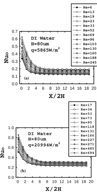
For the DI water flow, the heat transfer characteristics in the micro-scale channel are significantly reduced and are significantly smaller than the case of airflow. It is attributed to occurrence of the electrical double layer (EDL) that stays stagnant in the water flow along the channel wall (Pfhaler et al., 1990, 1991; Mala et al., 1996, 1997, 1998; Yang and Li, 1997, 1998; Yang et al., 1998; Arulanandam and Li, 2000; Qu et al., 2000; Ren and Li, 2001; Ren et al., 2001). The occurrence of EDL can reduce the water flow rate and cause significant reduction in the local Nusselt number, as shown in Figure 8. In the present case of pure DI water the EDL occurred is very thick. Mala et al. (1997) proposed that the EDL is very thick and is about 1 µm for millipore water (MPW) in microchannel. In addition, the present channel is constructed with the nonconductive materials, such as SU-8 photoresist, epoxy resin layer, Pyrex glass substrate and PMMA cover. It can be expected that large amount of electric charges can be generated and collected along the surface of nonconductive wall of the channel to cause a much thicker EDL that can greatly reduce the flow passage and lead to reduction in the local Nusselt number. The present local Nusselt number results in the water channel are greatly smaller than those in the airflow channel. Meanwhile, the normalized Nusselt number Nu/Re0.5 distributions are also compared with the published results (Obot, 2003) and were found much lower due to the occurrence of a very thick EDL in the water flow along the nonconductive wall surface. It is suggested that both two reasons described above cause the large reduction in the local Nusselt number in the present water channel flow. In addition, the normalized entrance length observed for DI water flow with q=5865 W/m2 at Re=6 in the
present channel is estimated and is about 5, as shown in Figure 8, which is also significantly longer than the theoretical normalized entrance length of 0.06 estimated by the previous equation in the large scale channel. However, the onset of transition to turbulent flow was not found in current results of DI water and the curves of the local Nusselt number distributions are very smooth and the oscillations induced by the onset of transition to turbulent flow are not found. This is attributed to the fact that all of the heat transfer data are obtained for the Reynolds numbers less than 1,000
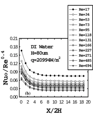
The normalized Nusselt number Nu/Re0.4 distributions are also greatly dependent on the Reynolds number variation, as shown in Figure 9. Hence, the thermal conductivity of water still affects the normalized Nusselt number Nu/Re0.4 distributions for DI water flow in the present channel, and the normalized Nusselt number Nu/Re0.4 distribution increases with decreasing the Reynolds number. In addition, the normalized Nusselt number Nu/Re0.4 distributions forq=5865 W/m2, as shown in Figure 9(a), are smaller than in the cases of q=20994 W/m2, as shown in Figure 9(b), due to a lower thermal conductivity of water in the case with a smaller heating power on the wall. Finally, the average Nusselt number is also very dependent on the Reynolds number and increases with increasing the Reynolds number, as shown in Figure 10. Clearly, it can be found that the average Nusselt number also increases with increasing the heating power along the wall. Especially, the slop of the average Nusselt number becomes smaller when the Reynolds number is greater than about 250. This critical Reynolds number for DI water flow is greatly lower than the case of airflow due to a higher kinetic viscosity and a higher thermal conductivity of DI water.
CONCLUSIONS
In the past, many empirical correlations have been proposed for microchannel heat transfer without verification. In fact, from the present results, we can find that some characteristics of flow and heat transfer in micro-scale channel are different from the large-micro-scale channel. The entrance lengths of air or DI water flow in the present micro-scale channel are longer than the theoretical entrance length in the large-scale channel. In addition, the local Nusselt number measured is much lower than in the large-scale channel due to the micro size effect for the micro channel air or DI water flow, and the EDL effect in the DI water flow. In addition, the normalized Nusselt number Nu/Re0.4 is significantly increased with increasing the heating power and decreasing the Reynolds number due to the increase in the thermal conductivity of both the air and the DI water flow, especially for the airflow. The investigations described above could be used to understand the heat transfer characteristics in the micro-scale flow heated channel.
ACKNOWLEDGMENTS
This research was sponsored by the National Science Council of Taiwan under contract No. NSC 92-2212-E-006-088.
Nomenclature
Dh = hydraulic diameter, 4HW/(H+W) H,W = half channel height, channel width
Re = Reynolds number, VDh/υ where ν is kinetic viscosity V = mean flow velocity in the channel
REFERENCES
[1] B. S. Choondal and V. G. Suresh, “A comparative analysis of studies on heat transfer and fluid flow in microchannels,” Proceedings of the Micro-Scale Heat Transfer Conference, Alberta, CA, 2002, pp. 80-92. [2] C. P. Tso and S. P. Mahulikar, “Laminar convection
behavior in microchannels in conventional thermal entry length and beyond,” IEEE/CPMT Electronics Packaging Technology Conference, 1998, pp.126-132. [3] Linan Jiang, Man Wong and Zohar Yitshak, “Phase change in microchannel heat sinks with integrated temperature sensors,” Journal of MEMS, Vol. 8, No. 4, pp.358-365, 1999.
[4] J. Pfahler, J. Harley, H. Bau and J. N. Zemel, “Liquid transport in micron and submicron channels,” Sens. Actuators 21/23, pp.431-434, 1990.
[5] W. Qu, G. M. Mala and D. Li, “Pressure-driven water flows in trapezoidal silicon microchannels,” Int. J. Heat Mass Transfer, Vol. 43, pp.353-364, 2000. [6] H. R. Chen, C. Gau, B. T. Dai and M. S. Tsai, “A
monolithic fabrication process for a micro-flow heat transfer channel suspended over an air layer with arrays of micro-sensors and heaters,” Sens. Actuators, Vol. A108/1-3, Nov. pp.81-85, 2003.
Air H=80um q=5865W/m2
X/2H
0 2 4 6 8 10 12 14 16 18 20Nu
o/Re
0. 4 0.0 0.4 0.8 1.2 1.6 2.0 2.4 Re=126 Re=211 Re=379 Re=506 Re=716 Re=1010 Re=1221 Re=1431 Re=1642 Re=1810 Re=2021 LargeChannel forH=3cm Gauetal.(1996)Figure 2 Comparisons of the current Nu/Re0.4 distributions
for airflow with the published results for large-scale channel.
Figure 3 The local Nusselt number distributions for airflow at different Reynolds numbers.
Figure 4 Nu/Re0.4 distributions for airflow at different Reynolds numbers.
Figure 5 The local Nusselt number distributions for airflow at different heating powers for (a) Re=127 and (b) Re=1015, respectively.
H=80um
X/2H
0 2 4 6 8 10 12 14 16 18 20Nu
o
0 2 4 6 8 10 12 Re=126 Re=506 Re=716 Re=1010 Re=1221 Re=1431 Re=1642 Re=1810 Re=2021 Air H=80um q=5865W/m2H=80um
X/2H
0 2 4 6 8 10 12 14 16 18 20Nu
o/Re
0. 4 0.0 0.2 0.4 0.6 0.8 1.0 R e= 126 R e= 211 R e= 379 R e= 506 R e= 716 R e= 101 0 R e= 122 1 R e= 143 1 R e= 164 2 R e= 181 0 R e= 202 1 Air H=80um q=5865W/m2Air
Re=127
H=80um
X/2H
0 2 4 6 8 10 12 14 16 18 20Nu
o
0 2 4 6 8 10 12 q=428W/m2 q=1714W/m2 q=3856W/m2 q=6855W/m2 q=10711W/m2(a)
Air
Re=1015
H=80um
X/2H
0 2 4 6 8 10 12 14 16 18 20Nu
o
0 2 4 6 8 10 12 q=1714W/m2 q=3856W/m2 q=6855W/m2 q=10711W/m2 (b) (a) (b) (c) (d)Figure 1 Fabrication process of the micro-flow heated channel.
Air H=80um
X/2H
0 2 4 6 8 10 12 14 16 18 20Nu
o/Re
0.4 0.0 0.2 0.4 0.6 0.8 1.0 1.2 Re=1015,q=1714W/m2 Re=1015,q=3856W/m2 Re=1015,q=6855W/m2 Re=1015,q=10711W/m2 Re=127,q=428W/m2 Re=127,q=1714W/m2 Re=127,q=3856W/m2 Re=127,q=6855W/m2 Re=127,q=10711W/m2Re
0 400 800 1200 1600 2000 2400Nu
av e 0 1 2 3 4 5 Air H=80um q=5865W/m2 (a)Figure 6 Distributions of the dimensionless parameter Nu/Re0.4 for airflow at different heating powers for Re=127 and 1015, respectively.
Figure 7 The average Nusselt number variation for airflow at (a) different Reynolds numbers and (b) different heating powers, respectively.
Figure 8 The local Nusselt number distributions of DI water flow at different Reynolds numbers for (a) q=5865 W/m2 and (b) q=20994 W/m2.
q(W/m
2)
0 2500 5000 7500 10000 12500Nu
av e 0 1 2 3 4 5 Re=127 Re=1015 Air H=80um (b) 0DI Water
H=80um
q=5865W/m
2X/2H
0 2 4 6 8 10 12 14 16 18 20Nu
o
0.0 0.1 0.2 0.3 0.4 0.5 0.6 0.7 Re=6 Re=13 Re=19 Re=23 Re=33 Re=52 Re=69 Re=96 Re=103 Re=130 Re=160 Re=188 Re=245 (a)DI Water
H=80um
q=5865W/m
2X/2H
0 2 4 6 8 10 12 14 16 18 20Nu
o
/Re
0.4 0.00 0.03 0.06 0.09 0.12 0.15 0.18 0.21 Re=6 Re=13 Re=23 Re=33 Re=52 Re=69 Re=103 Re=130 Re=160 Re=188 Re=245 (a)DI Water
H=80um
q=20994W/m
2X/2H
0 2 4 6 8 10 12 14 16 18 20Nu
o
0.0 0.2 0.4 0.6 0.8 1.0 Re=17 Re=34 Re=53 Re=73 Re=95 Re=118 Re=131 Re=166 Re=227 Re=271 Re=485 Re=694 (b)DI water H=80um
Re
0 200 400 600 800Nu
ave 0.0 0.1 0.2 0.3 0.4 0.5 q=5865W/m2 q=20994W/m2Figure 9 Nu/Re0.4 distributions of DI water flow at different Reynolds numbers for (a) q=5865 W/m2 and (b) q=20994 W/m2, respectively.
Figure 10 The average Nusselt number variation of DI water flow at different Reynolds numbers for q=5865 W/m2 and 20994 W/m2, respectively.