行政院國家科學委員會專題研究計畫 成果報告
局部膺復體人工植牙之植入設計與分析(2/2)
計畫類別: 個別型計畫
計畫編號: NSC93-2320-B-006-013-
執行期間: 93 年 08 月 01 日至 94 年 08 月 31 日 執行單位: 國立成功大學醫學工程研究所
計畫主持人: 張志涵 共同主持人: 黃振勳 計畫參與人員: 黃恆立
報告類型: 完整報告
報告附件: 出席國際會議研究心得報告及發表論文 處理方式: 本計畫可公開查詢
中 華 民 國 94 年 12 月 1 日
中文摘要:
本研究的主要目的在於探討局部贋覆體人工植牙在(1)不同植入結構的人工 牙根,包括大直徑之人工牙根與雙人工牙根(以兩根人工牙根支撐單一牙冠,以 模擬雙牙根的結構)、(2)假牙相連與不相連與(3)不同排列方式的植入設計(直線排 列、偏頰測非直線排列與偏舌側非直線排列),其骨質與人工牙根的應力分布,
並找出較佳的植入設計,以降低過度負荷所造成的損害。本研究運用有限元素模
擬分析結合電腦斷層掃描影像與CAD 系統等三維模型建構之技術,所分析的模
型具有精確之解剖幾何外形,並使用非等向性之骨質材料性質與 p-mothod 之收
斂性測試,在兩種負荷模式(齒窩處施加垂直力與齒尖處施加斜向力)下,進行參 數間的比較與分析,此外,本研究亦透過應變規實驗驗證有限元素模擬的合理 性。在結果方面,有限元素模擬與應變規實驗分析在應變數值上雖有差異,但兩
者具有相當高之相關係數(r2=0.97)。在標準直徑、大直徑人工牙根與雙人工牙根
的比較方面,發現在臼齒區種植大直徑人工牙根或雙人工牙根,與標準尺寸的人 工牙根相比,可大幅降低人工牙根周圍骨質的應力,其原因則是大直徑的人工牙 根或雙人工牙根皆有效增加人工牙根與骨質的界面面積。在假牙相連與不相連的 探討方面,結果發現,使用相同直徑之人工牙根的植入,其兩者之應力值並沒有 明顯差異,但是在假牙相連的情況下,並在大臼齒位置種植結構較強的人工牙 根,例如:大直徑的人工牙根或雙人工牙根,卻有助於降低小臼齒位置之周圍骨 質的應力值。在局部臼齒缺牙區進行三根以上的人工牙根植入,使用非直線的種 植方式,雖然可以降低人工牙根本身的應力植,但是在最重要的周圍骨質應力方 面,非直線的人工牙根排列並無法提供降低骨應力值的好處,並會在某些人工牙 根周圍骨質產生高應力,增加人工牙根植入失敗的危險性。
關鍵詞:局部贋覆體之人工植牙、有限元素分析、大直徑人工牙根、雙人工牙根、
相鄰假牙相連、人工牙根的排列(直線排列或非直線排列)。
Abstract:
The aim of this study is to investigate the effects of treatment designs, which various supporting implants (standard, wide and two implants), prosthetic crowns splinted or non-splinted and different placements of treatment (in-line, buccal offset and lingual offset placements) in implant-supported partial prosthesis. Finite element (FE) analysis was used to analyze these design parameters in this study. Combing the technologies of computer tomography (CT) images programs and computer-aided design (CAD) system, the finite element models with an accurate anatomic geometry were created. The anisotropic material properties of bone are assumed, and two loading conditions (vertical and oblique loads) are achieved in the models with p-method convergent test. The experimental strain gauge verification (ESGV) is also performed to validate the finite element simulation. The FE simulation in this study was validated because of a high correlation existed between ESGV and FE simulation.
Comparing the results of wide implant, two implants and prosthetic crown splinted or non-splinted, embedding wide implant or two implants showed the better stress decrease in bone than standard size of implant. The benefit of stress sharing effect only was achieved in the treatment design of splinting crowns with one standard implant and one wide implant (or two implants) because the evidence of the decrease of bone stress was shown around the standard implant. For the comparison results of in-line and offset placements, using offset placements could decrease the implant stresses. However, the offset placements showed no benefit in bone stress decreasing over the in-line placement, and further, it might increase the bone stresses around some implants result in the risk of implant’s instability.
Keywords: implant-supported molar restoration, finite element analysis, wide implant, two implants, splinted crowns, arrangement of implants (in-line and offset placement).
Tables of Contents
Abstract……….…I 中文摘要………..II Table of contents………..III List of tables……….IV List of figures………...V
1. Introduction………..……….………..…...1
1.1 Problems of implant-supported partial prostheses………….……….……..….…1
1.2 Treatment designs of implant-supported partial prostheses………..……….3
1.3 Motivation and objectives………..………5
2. Materials and methods………..………….6
2.1 Finite element modeling.………....6
2.1.1 Imaging processing………..….…...6
2.1.2 Computer aided design (CAD) processing and finite element modeling…...6
2.1.3 Anisotropic materials properties……….………...6
2.1.4 Loading condition and boundary condition………….………..…...7
2.1.5 The convergence criteria……….……….…………..….7
2.1.6 The description and dimensions of models……….7
2.2 Experimental Strain Gauge Verification………..…………..8
3 Results………...……….………..……….13
4. Discussion………...19
5. Conclusion………22
6. References………22
7. 計畫成果自評……….…25
8. 附錄……….…26
List of Tables
Table 1 Material properties of the finite element models………...……9 Table 2 Design parameters of dental implant and prostheses on posterior partial
edentulous (2nd premolar and 1st molar) restoration……….…10 Table 3 Young’s Modulus and Poisson’s ratio of each material of the experimental model was assigned to the validation finite element model……….12 Table 4 The mean microstrains (MS) and standard error (SE) measured form the experimental in-vitro test, which were compared with strains of the validation finite element model………..15 Table 5 The highest maximum principle stress value (MPa) of each implant……….17 Table 6 The maximum von-Mises stress value (MPa) of cortical and trabecular bone around each implant……….18
List of Figures
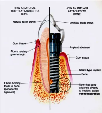
Fig 1 The bio-structure of natural tooth and implant which attaches to bone. (Taylor 1990)……….…2 Fig 2 The use of the standard size of implant to support the prosthetic molar crown, the larger ratio of crown-to-root induces the various direction of the potential bending moment. (Balshi 1996)………...2 Fig 3 Widening the diameter of implant can reduce the ratio of crown-to–root.
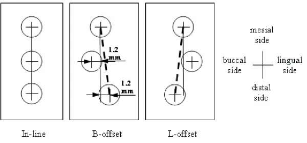
However, this value is further minimized by two implants treatment. (Balshi 1997)…4 Fig 4 The crowns of these implants are modeled as connected and disconnected to mimic (a) the splinted and (b) non-splinted designs………..4 Fig 5 Number of implant, implant position and arrangement of the implant affect the stress levels on the implants. (Rangert 1997)………...5 Fig 6 (a) The CT image of mandible and crown (b) The contours of crown, cortical bone and trabecular bone………..…..9 Fig 7 Illustrations of (a) Model Spl-S, the splinted crown were supported by one standard implants at the 1st molar site and one standard implant at the 2nd premolar site. The oblique loads (100N each) were applied on the buccal functional cusps. (b) Model Spl-T, the splinted crown were supported by two standard implants at the 1st molar site and one standard implant at the 2nd premolar site. (c) Model nSpl-W, the non-splinted crowns were supported by one wide implant at the 1st molar site and one standard implant 2nd at the premolar site……….….10 Fig 8 The placement designs of the ISPP; the distance of offset was set as 1.2mm.
Because of the anatomic limitation about the buccolingual width of mandible on premolar site, the mesial-distal implant position was not shifted in all three models..11 Fig 9 (a) The iso-view and (b) the buccaolingual section of the on-line mode of 3D FE model of the implant-supported posterior prostheses………...…..11 Fig 10 (a) The experimental model was fixed by the aluminum clamping jig with 45 degree of lingual inclination. (b) The self-development of load apply machine….…12 Fig 11 The strain gauges were attached on the lingual side of the experimental mandibular mold. The resistors of each strain gauge were set along the direction of minimum principle strains obtained from the FE model. Arrows indicated the four loading points (dimples) located on the central fossa and functional cusps………....12 Fig 12 The von Mises stress distributions on the crest bone for the models with (a) splinted crowns and (b) non-splinted crowns……….….16 Fig 13 The peak von Mises stress of cortical bone around each implant for (a) the splinted crown and (b) the non-splinted crown. Implant 1 is placed in the 2nd premolar region while Implant 2 and Implant 3 are placed in 1st molar region……….….17 Fig 14 The von-Mises stress distribution of the crestal bone of the ISPP along three
placement designs under the vertical loading condition………..…18 Fig 15 The von-Mises stress distribution of the crestal bone of the ISPP along three placement designs under the oblique loading condition………..…19
1. Introduction
1.1 Problems of Dental Implant-Supported Partial Restoration (ISPP)
The biomechanical behavior of dental implant is quite different from natural teeth. One of the major reasons is a lack of the function of periodontal ligament (Fig 1). Because the material of periodontal ligament is a soft tissue, it could function as an intermediate cushion element (Weinberg 1993) which absorbs the impact force and uniformly transfers the occlusal forces into the surrounding bone. However, the bio-structure of dental implant is directly connected with bone. That would cause the non-uniform stress pattern at bone and might induce the biomechanical overloading failures in implant and bone (Quirynen 1992; Rangert 1995). This overload would cause the microdamage accumulation at bone and results in primary marginal bone loss (Hansson 2003). Then the bacterial invasion might occur in the area of the bone loss and cause the serious progressive bone resorption (Spiekermann 1995). This kind of insufficient bone support is dangerous for losing implant stability and increasing the risk of the implant fracture.
The implant restoration presents a biomechanical challenge in implant-supported partial prostheses (ISPP). That is because most of the ISPP cases used in premolar and molar area, and large chewing forces in the premolar or molar region would induce the bending moments that contribute to potential bending overload on bone and implant. That could be detrimental to the prostheses and alveolar bone (Rangert 1995;
Ishigaki 2003), and generate marginal bone loss, decrease implant stability, and thus imperil the implant and its supra-structures (Brunski 1999; Miyata 2000).
The inappropriateness of the crown-implant ratio was obviously happened in the molar region. On the single, implant-supported molar restoration the dimension of the prosthetic crown are apparently larger than the size of the implant (Fig 2). When bite forces are executed on the crown, the large crown-implant ratio will easily occur the unfavorable bending moment and will increase the possibility of implant failure (Balshi 1996).
Using different implant designs and treatment protocols of implants seems to attribute the better biomechanical performance in the molar restoration. However, what kinds of implant designs and treatment protocols are effective to decrease the overload in implant and bone, especially at the molar region, it seems an issue.
Therefore, the investigation of the biomechanical effect of implant designs and treatment protocols on implant-supported partial prostheses is essential because this information could help implant designers and dentists know of how to decrease
potential overload in both implant and bone and prevent the implant failure.
Fig 1 The bio-structure of natural tooth and implant which attaches to bone. (Taylor 1990)
Fig 2 The use of the standard size of implant to support the prosthetic molar crown, the larger ratio of crown-to-root induces the various direction of the potential bending moment. (Balshi 1996)
1.2 Treatment Designs for Implant-Supported Partial Prostheses
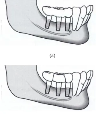
Researches studying the treatment designs for implant-supported partial prostheses in molar area showed quite incompatible results. For single molar restoration, using wider implants (Fig 3) could decrease the percentage of failures (van Steenberghe 1995; Davarpanah 2001) and increase the removal torque (Ivanoff 1997). Likewise, using two implants (Fig) to support a single crown could reduce the rotational moment (Bahat 1996) and decrease implant mobility (Balshi 1996). Either wide implant or two implant has its own advantages. However, the biomechanical criteria for choosing one design over the others have not been defined. It has been stipulated that using large diameter of implants and two implants can increase stiffness of the implant(s) and bone-to-implant contact surfaces (Langer 1993; Balshi 1997). Nevertheless, the use of wide-diameter implants could lead to bone loss when narrow posterior ridges exist (Davarpanah 2001). Higher failure rates for wide implant have been found in clinical reports (Attard 2003, Ivanoff 1999). Furthermore, the stress states in the narrow space of bone between the two implants are unclear.
Splinting the adjacent crowns (Fig 4) is a proposition to decrease peak stresses by load sharing (Wang 2002, Guichet 2002). This is why partial prostheses usually used for implant treatment on the partial edentulous area. Nevertheless, some clinical studies didn’t share this concussion. They found no significant difference between the splinted and non-splinted prosthetic crowns (Herbst 2000) or there are worse results on the splinted prostheses (Naert 2002; Rangert 1995).
Non-straight line placement of implants, which is named the offset placement of implants (Fig 5) have been put in use clinically in partial edentulous of molar restoration for several years. Studies (Rangert 1995; Rangert 1997) indicated that the bending moment at all implants would be diminished if the implants were placed as offset placement. The research of Daellenbach et al.(1996) showed that the forces and moments of all the implants on ISPP were decreased by the offset placement.
However, some articles had apparent disagreements on the effect of offset placement.
These studies found that the offset placement of implants did not always decrease the load in all implants (Weinberg 1996; Sato 2000). Instead, it would induce high stresses in surrounding bone(Itoh 2004; Akca 2001).
Fig 3 Widening the diameter of implant can reduce the ratio of crown-to–root.
However, this value is further minimized by two implants treatment. (Balshi 1997)
Fig 4 The crowns of these implants are modeled as connected and disconnected to mimic (a) the splinted and (b) non-splinted designs.
(b) (a)
1.3 Motivation and objectives
For implant-supported partial prostheses, the implant and treatment designs are commonly used in clinic. However, their clinical outcomes and research reports were discordant. Some of these designs, such as two implants, splinting crowns and spiral thread characteristic, the mechanisms of implant and bone’s stress/strain distribution are still unclear. Besides, some finite element (FE) studies showed the limitations, such as ignoring the real pattern of cortical shell, anisotropic material properties of bone, and the convergent validation all raised the error for result prediction.
The aim of this study, therefore, is to investigate the effects of various implant and treatment designs of implant-supported partial prostheses in molar area. The results of these design parameters are evidenced by anatomic three-dimensional FE analysis and the parameters examined are listed as follows:
(1) Different supporting structures of implants. Standard, wider size of implants and two implants are selected to estimate the benefit of stress decreasing at bone.
(2) Splinted and non-splinted prosthesis. The adjacent crowns are modeled as connected and disconnected on partial molar restoration to assess the contribution of their load sharing effects.
(3) Arrangement of Implant placements. In-line, buccal offset and lingual offset Fig 5 Number of implant, implant position and arrangement of the implant affect the stress levels on the implants. (Rangert 1997)
placements of implants on partial molar restoration are analyzed for their biomechanical effects.
The experimental strain gauge verification (ESGV) is also performed to validate the finite element simulation.
2. Materials and Methods 2.1 Finite element modeling
2.1.1 Imaging processing
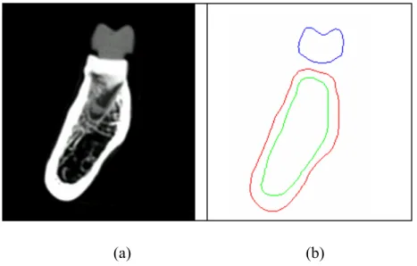
The posterior mandible (distal of the 2nd premolar to the mesial of the 2nd molar) was taken out from a human dry skull and, frontal sections of computer tomography (CT) images (1 mm interval between images) were obtained. From each CT image (Fig 6a), material boundaries were delineated by an in-house imaging program. This program employs various thresholds in CT number and searches for maximum gradient values of the CT number, which can be used to detect the boundary pixels between different materials (Chang 1990). A depth first search algorithm is then used to find the nearest boundary pixels to re-number the pixels and construct the contour of each material (Fig 6b). The stack of these contours are then put into ANSYS (Swanson Analysis Inc., Huston, PA, USA) to generate a three-dimensional solid model of the mandible.
A resin crown of the implant was duplicated from the first molar, which was then scanned by CT. The same procedure mentioned above was then used to create a three-dimensional solid model of the crown.
2.1.2 Solid model processing and the element type
All implant models were cylindrical with the length of 11.5mm. The detail components of abutment were omitted. The solid models of the posterior mandible, the crown, and the implant were arranged by surgical allocation. After all models were combined by overlap of the Boolean operation, 10-node tetrahedral p-elements (ANSYS solid 148) were used to construct the finite element models.
2.1.3 Anisotropic materials properties
The material properties of the cortical and trabecular bone of the six models were applied as transversely isotropic and linearly elastic (O’Mahony 2001). For cortical bone the buccolingual plane was elastic isotropic along the axis of mesiodistal
isotropic along the axis of inferosuperior direction. The materials of the implant and prosthetic crown were assumed to be isotropic and linearly elastic (Sertgoz 1996;
Ciftci 2000). All material properties are listed in Table 1.
2.1.4 Loading condition and boundary condition
The loading condition was distinguished into two loading modes for evaluation.
The vertical loading mode is vertical forces at central fossas, and the oblique loading mode is oblique forces at functional buccal cusps with 45 degree of lingual inclination.
The magnitude of each force was 100 Newton and was applied at each prostheses unit.
The boundary condition was constrained at the bottom surface of the mandibular bone in all directions. In this study, the region of interest was near the ridge of the mandibular, hence the interference caused by the boundary constraint did not existed.
The bone-implant interface and crown-implant interface were rigidly bonded in all models.
2.1.5 The convergence criteria
All models reached convergence based on the changes of global strain energy less than 5%. The p-element method in ANSYS was used for the convergence tests and the p-value was set to be between 2 (the initial value) and 8 until the convergence was achieved. Most models got converged at p = 4.
2.1.6 The description and dimensions of models
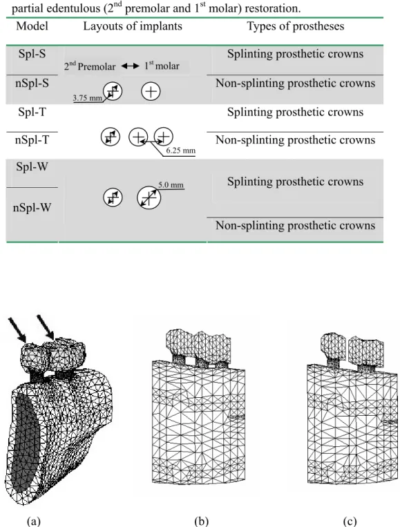
To investigate the effects of crown splinting and various molar implant supports, three implant support conditions (standard implant, wide implant, and two implants) combined with two crown states (splinted and non-splinted crown) were modeled. In total, six finite element models constructed with 10-node tetrahedral p-element (ANSYS solid 148), were generated. To label these models, two sets of symbols were used. The first set of the symbol indicates the splint factor: ‘Spl’ for splinted and
‘nSpl’ for non-splinted. The second set of the symbol represents the implant’s configurations, i.e., S for standard implant (3.75mm in diameter), W for wide implant (5 mm in diameter) and T for two implants (3.75mm in diameter). Table 2 summarizes the notations of these six models. The finite element models of Spl-S, Spl-T and nSpl-W are shown in Fig 7. In these six models, the mandible segment was approximately 32mm mesiodistally, 12 mm buccolingually at the premolar site, and 15 mm buccolingually at the molar site.
In addition, the solid models included a posterior mandible, a splinted crown and three implants (3.75mm in diameter) were arranged along surgical allocation of three kinds of placements (Model In-line, Model B-offset and Model L-offset) as shown in
Fig 8 and Fig 9. Model In-line was defined as insetting implants along a straight line.
Model B-offset and Model L-offset were defined as insetting implants to interlace buccal and lingual offset placements. In these three models, the mandible segment was approximately 38 mm mesiodistally, 11 mm buccolingually at the premolar site, and 16.7 mm buccolingually at the molar site.
2.2 Experimental strain gauge verification (ESGV)
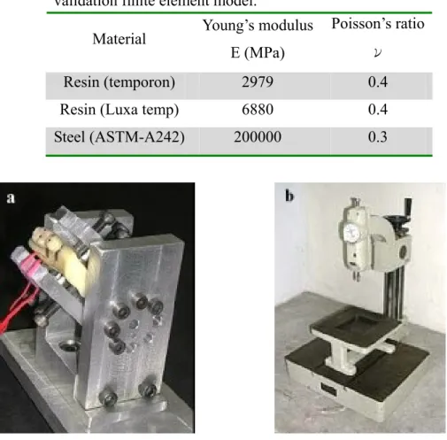
The acrylic resin (Tempron, GC, Kasugai, Japan), a posterior mandibular sample was duplicated from the same mandibular cadaver used in the FE modeling. The splinted second premolar and first molar crown (crown type of Model Spl-S) was also replicated with another acrylic resin (Luxatemp, DMG, Hamburg, Germany). The material properties of these two resins were measured by the uni-axial compressive test on cube specimens which were plastered with bi-axial strain gauges. The Young’s modulus was calculated from the slope of the stress-strain curve within the elastic region. The Poisson’s ratios were obtained from the quotient of the transverse (εt) and axial (εa) strains, that is, ν = εt /εa. These material properties are listed in Table 3 and were used in the validation FE model.
Two stainless steel cylinders (diameter 3.75mm, length 12mm), mimicking the implants, were embedded in the mandibular model with the splinted crown. Two single-axis strain gauges (KFG-1-120-C1-11L1M2R, KYOWA, Tokyo, Japan) were cemented on the lingual side of mandibular model near the implant with cyano-acrylate cement (CC-33A, KYOWA, Tokyo, Japan) (Fig 23), oriented toward the directions of the minimal principal strain obtained from the validation FE model.
In order to evaluate various loading effects, a clamping jig was designed with an adjustable screw-system so that the vertical load could be transferred into an oblique load on the implant/mandible construct (Fig 10). On the premolar crown and the molar crown, a force was applied either at the center fossa with vertical direction or at the buccal cusp with 45 degree buccal inclination, hence in total there were four loading conditions (Fig 11). For each of these four loading cases, two force magnitudes, 100N and 200N, were applied. The strain values were recorded through the data acquisition system (instruNet Hardware, GW instruments, Inc , MA, USA).
Each measurement was repeated three times.
The FE model “Spl-S” was used as the validation FE model for the experimental validation. Therefore, the material properties, loading and boundary conditions of the validation FE model were re-assigned based on the experimental setup. The surface nodes on the lingual mandible near the implant, corresponded to the measured areas
the comparison with principal strains measured in experimental model.
Table 1 Material properties of the finite element models Material
Young’s modulus E (MPa)
Poisson’s ratio ν
Shear modulus G (MPa) Ex 12600 νxy
νyz
0.3
0.253 Gxy 4850 Ey 12600 νxz
νyx
0.253
0.3 Gyz 5700 Cortical
bone
Ez 19400 νzy
νzx
0.39
0.39 Gxz 5700 Ex 1148 νxy
νyz
0.055
0.01 Gxy 68 Ey 210 νxz
νyx
0.322
0.01 Gyz 68 Trabecular
bone
Ez 1148 νzy
νzx
0.055
0.322 Gxz 434 Titanium 110000 0.35
Porcelain 70000 0.19
The vectors of x, y and z indicate the buccolingual, infero-superior and mesiodistal direction, respectively.
Fig 6 (a) The CT image of mandible and crown (b) The contours of crown, cortical bone and trabecular bone.
(a) (b)
Table 2 Design parameters of dental implant and prostheses on posterior partial edentulous (2nd premolar and 1st molar) restoration.
Model Layouts of implants Types of prostheses
Spl-S Splinting prosthetic crowns
nSpl-S Non-splinting prosthetic crowns
Spl-T Splinting prosthetic crowns
nSpl-T Non-splinting prosthetic crowns
Spl-W
Splinting prosthetic crowns nSpl-W
Non-splinting prosthetic crowns
(a) (b) (c)
Fig 7 Illustrations of (a) Model Spl-S, the splinted crown were supported by one standard implants at the 1st molar site and one standard implant at the 2nd premolar site. The oblique loads (100N each) were applied on the buccal functional cusps. (b) Model Spl-T, the splinted crown were supported by two standard implants at the 1st molar site and one standard implant at the 2nd premolar site. (c) Model nSpl-W, the non-splinted crowns were supported by one wide implant at the 1st molar site and
3.75 mm
2nd Premolar 1st molar
6.25 mm
5.0 mm
Fig 9 (a) The iso-view and (b) the buccaolingual section of the on-line mode of 3D FE model of the implant-supported posterior prostheses.
Fig 8 The placement designs of the ISPP; the distance of offset was set as 1.2mm.
Because of the anatomic limitation about the buccolingual width of mandible on premolar site, the mesial-distal implant position was not shifted in all three models.
Table 3 Young’s Modulus and Poisson’s ratio of each material of the experimental model was assigned to the validation finite element model.
Material Young’s modulus E (MPa)
Poisson’s ratio ν
Resin (temporon) 2979 0.4
Resin (Luxa temp) 6880 0.4
Steel (ASTM-A242) 200000 0.3
Fig 10 (a) The experimental model was fixed by the aluminum clamping jig with 45 degree of lingual inclination. (b) The self-development of load apply machine.
Fig 11 The strain gauges were attached on the lingual side of the experimental mandibular mold. The resistors of each strain gauge were set along the direction of minimum principle strains obtained from the FE model. Arrows indicated the four loading points (dimples) located on the central fossa and functional cusps.
3. Results
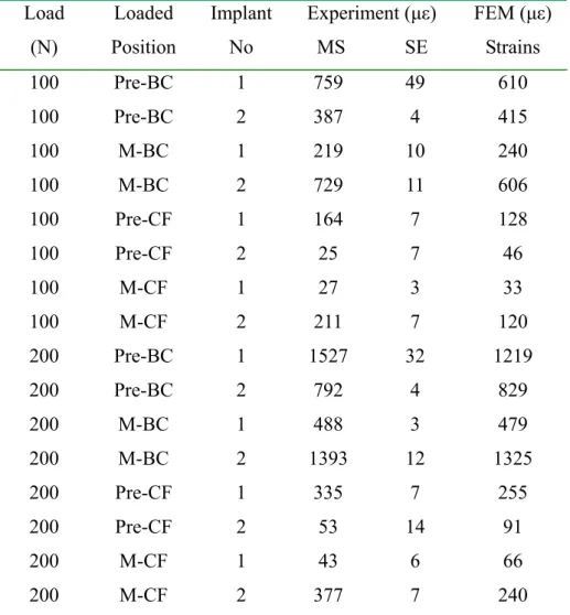
Table 4 shows the minimum (compressive) principal strains in the experimental model and the validation FE model under the four loading conditions. The experimentally measured compressive strains were doubled when the loading increased from 100N to 200N which indicated a linear status of this model. In general, the experimental strains were higher than the simulated strains and the differences were 10% to 50%. However, comparing within all loadings, the experimental and simulated results did show a consistent relationship. This indicated a high correlation between the experimental and the finite element approaches (r2=0.97).
On the results of splinted or non-splinted crowns with standard, wide and two implants
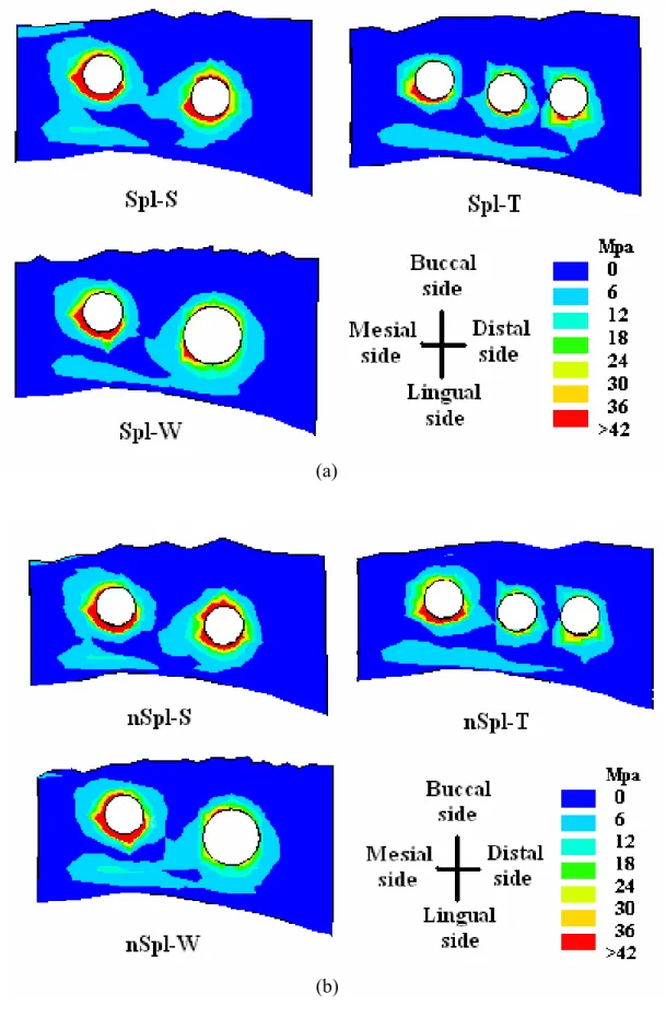
Fig 12 shows the von Mises stress distributions on the cortical bone of the six FE models. High stresses were located at the alveolar crest around the implants, which matched the clinical observations of crestal bone loss (Rangert 1995). In addition, no stress was concentrated at the space between the two implants of two-implant models (Models Spl-T and nSpl-T).
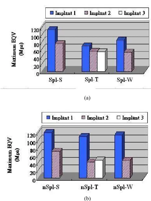
The peak von Mises stresses on the cortical bone around each implant of the six models are shown in Fig 13. With the splinted prosthesis, the peak stresses of bone at the first molar region decreased by 29% in Model Spl-T and 31% in Model Spl-W, respectively, as compared to Model Spl-S. Likewise, with non-splinted prosthetic crowns, the peak stresses of bone at the first molar region were reduced by 37% in Model nSpl-T and 35% in Model nSpl-W, respectively, as compared to Model nSpl-S.
However, the peak stress difference between the wide implant and two implants, for both splinted and non-splinted groups, were not significant.
As for the splinting effect, with a standard implant under molar crown, the differences of peak bone stresses between Model Spl-S and Model nSpl-S were not significant at both premolar and molar regions. However, in two-implant models, the peak stress at premolar region for splinted crown (Model Spl-T) was decreased by 25% as comparing with non-splinted crown (Model nSpl-T). In the wide implant models, the peak stress at premolar region was decreased by 36% as comparing Model Spl-W with Model nSpl-W. This demonstrated that the splinted factor is vital only if the support of the implant at the first molar region is stronger than that at the premolar region.
On the results of in-line, buccal offset and lingual offset placements
To present the simulated results more clearly, the three implants were labeled as implant #1, #2 and #3 from mesial to distal directions, that is for implants placed into
premolar, first molar and second molar regions respectively. For each implant, the peak maximum principal (tensile) stress, the potential fracture index for metal, is located on the implant neck for all three models under both vertical and oblique loading modes. The oblique loading increased the implant stress by at lease 5 times than that of the vertical loading as listed in Table 5. Compared with the In-line placement, only the implant #2 of the L-offset placement under the vertical loading presented a slight peak stress increasing of 1.4%. All the other implants of the buccal and lingual offset placements demonstrated a peak stress decreasing up to 17% and 22% under the vertical and oblique loadings respectively. The largest peak tensile stress among the three implants occurred in implant #1 and the offset placements could provide a 7% of peak stress reduction as compared with the In-line placement on this implant.
The peak von-Mises stress values of cortical and trabecular bones around each implant are shown in Table 6. The peak stresses in cortical bone occurred in the crestal cortex area, and for the trabecular bone the peak stresses occurred near the apex of the implant. Comparing with the In-line placement, under vertical loading, the peak stress of cortical bone was increased by 19% around implant #2 of B-offset placement and by 5.9% around implant #3 of L-offset placement. However, in L-offset placement the peak stress of cortical bone was decreased by 13% around implant #1. The peak stress of trabecular bone around implant #2 was increased by 30% in B-offset placement and by 66% in L-offset placement. In contrast, the peak stress of trabecular bone around implant #1 was decreased by 22% in B-offset placement and by 14% in L-offset placement.
Under oblique loading, the peak stress at cortical bone was increased by 16%
around implant #2 of B-offset placement and by 5.1% around implant #3 of L-offset placement as compared to the In-line placement. However, in the L-offset placement the cortex peak stress was decreased by 9.9% around both implant #1 and #2. In the B-offset placement, the peak stresses of trabecular bone around each implant presented only minor changes. In the L-offset placement, the peak stresses of trabecular bone raised by 14% and 49% around implant #1 and #2 respectively and diminished by 15% around implant #3.
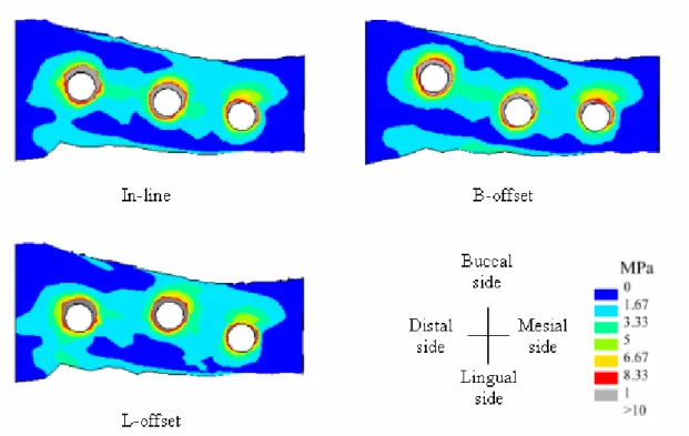
The stress distributions of crestal cortical bone under vertical loading and oblique loading were displayed in Fig 14 and Fig 15. The stress concentration occurred at crestal cortical bone in all models. In addition, comparing the area of gray strips (high stress region) around each implant in Fig 14 and Fig 15, it showed no difference between in-line and offset placements.
Table 4 The mean microstrains (MS) and standard error (SE) measured form the experimental in-vitro test, which were compared with strains of the validation finite element model.
Load (N)
Loaded Position
Implant No
Experiment (με) MS SE
FEM (με) Strains 100 Pre-BC 1 759 49 610
100 Pre-BC 2 387 4 415
100 M-BC 1 219 10 240 100 M-BC 2 729 11 606 100 Pre-CF 1 164 7 128
100 Pre-CF 2 25 7 46
100 M-CF 1 27 3 33
100 M-CF 2 211 7 120 200 Pre-BC 1 1527 32 1219
200 Pre-BC 2 792 4 829
200 M-BC 1 488 3 479 200 M-BC 2 1393 12 1325 200 Pre-CF 1 335 7 255 200 Pre-CF 2 53 14 91
200 M-CF 1 43 6 66
200 M-CF 2 377 7 240 Pre-BC = Buccal cusp of the 2nd premolar; M-BC = Buccal cusp of the1st molar; Pre-CF = Central fossa of the 2nd premolar; M-CF = Central fossa of the 1st molar
Fig 12 The von Mises stress distributions on the crest bone for the models with (a) splinted crowns and (b) non-splinted crowns.
(a)
(b)
Table 5 The highest maximum principle stress value (MPa) of each implant
In-line B-offset L-offset Implant
no. V O V O V O
#1 16.9 141.1 16.35 131.6 16.85 131.04
#2 16.5 104 14.44 87.89 16.73 81.06
#3 14.58 82.25 12.16 77.34 12.03 69.09 The symbolisms of V and O are represented the vertical loading
and oblique loading modes respectively.
(a)
(b)
Fig 13 The peak von Mises stress of cortical bone around each implant for (a) the splinted crown and (b) the non-splinted crown. Implant 1 is placed in the 2nd premolar region while Implant 2 and Implant 3 are placed in 1st molar region.
Table 6 The maximum von-Mises stress value (MPa) of cortical and trabecular bone around each implant.
Cortical bone Trabecular bone
In-line B-offset L-offset In-line B-offset L-offset Implant
no.
V O V O V O V O V O V O
#1 16.47 51.06 17.3 49.96 14.41 46.01 1.26 3.56 0.98 3.68 1.09 4.04
#2 20.42 59.31 24.26 68.72 21.07 56.69 1.19 3.71 1.55 3.62 1.98 5.54
#3 27.46 77.56 27.08 76.75 29.07 81.51 1.57 5.19 1.64 5.27 1.36 4.43 The symbolisms of V and O are represented the vertical loading and oblique loading modes
respectively.
Fig 14 The von-Mises stress distribution of the crestal bone of the ISPP along three placement designs under the vertical loading condition.
4. Discussion
The predicted principal strains by the validation FE model had a trend similar to those measured from ESGV among all loadings. The deviations in strain values between the ESGV and the FE simulation may be attributed to the measuring error in material properties, and the loading locations and directions between two approaches.
Besides, the orientation of the strain gauge, which does not align perfectly with the direction of principal strains, may also contribute to the deviations in strain. However, these deviations were proportionally changed in response to the alternation of biomechanical parameters in the models. For a purpose of comparing different implant designs, the FE simulation in this study was, therefore, verified.
The advantage of the present FE models was assured by the computed tomography images. In general, the simulated results of FE modeling depend considerably on the geometric structures of the models. In previous finite element studies, the mandibular model was either simplified as a rectangular configuration (Stegaroiu 1998; Wang 2002) or constructed by digital laser scanner (Ciftci 2000;
Akca 2001). The latter approach provides accurate surface topography but lacks the Fig 15 The von-Mises stress distribution of the crestal bone of the ISPP along three placement designs under the oblique loading condition.
cortical shell information, which may over/under predict stress/strain distribution of bone around the implant. Further, by introducing the anisotropic model (O’Mahony 2001), the characteristic of bone material was better reflected.
The investigation of splinted or non-splinted crowns with standard, wide and two implants
The use of the wide implant or two implants in the molar region can provide the advantage of reducing stress in the surrounding bone as shown in this study. This is because of the increased structural capacity and the enlarged bone-implant contact area offered by these implants. Balshi et al. (1996) indicated that a molar crown supported by a standard size implant can easily introduce large bending moments to bone because the dimension of the crown is usually greater than the diameter of the implant. Therefore, the wide implant or two implants are suggested for placement at the molar region to reduce the possibility of overload, which may lead to implant failure associated with the marginal bone loss (Rangert 1995). However, whether the wide-diameter implant (D 5.0mm) or two implants (D 3.75mm) is preferred for the edentulous molar restoration is still an issue. Based on the outcomes of this study;
differences between these two treatments are not significant. Therefore, with sufficient posterior mandibular bone width (buccal-lingual direction), the wide implant is suggested to reduce the surrounding bone stress due to the simplicity of its surgical procedures. However, according to the report of the Davarpanah et al. (2001), placing the wide implants in narrow posterior ridges can lead to marginal bone loss that may raise the risk of implant failure. Therefore, in the cases of insufficient posterior mandibular bone width, two implants are preferred because the stress reduction by two implants is about the same as that induced by the wide implant.
Further, the narrow distance (2.5 mm in this study) between the two implants of two-implant treatment would not increase the bone stress. Nevertheless, it is necessary to note that, recent clinic reports (Attard 2003, Ivanoff 1999) showed that using wide implants could result in higher failure rates than that of the standard implant. However, the authors pointed out that the failure might be associated with the surface treatment and shape of the implant and patients’ bone quality rather than the usage of wide implants.
Some scientific data suggested that prosthetic crown splinting had biomechanical advantage and could raise the success rate because occlusal force could be shared through splinted crowns, thus, decreasing the peak-stresses (Guichet 2002; Wang 2002). However, there is insufficient quantitative evidence to support this hypothesis.
Wang et al. (2002) had developed simplified FE models to evaluate this splinting effect and demonstrated that splinting the prosthetic crowns could reduce stresses in bone. Similar observations were presented in the study of Guichet et al. (2002) using photoelastic models. However, in their simulations the implant structures were loaded on the premolar only. When loading is applied to a single crown and, by splinting the crowns, the loading would redistribute itself through the implant under the unloaded crown, and then the peak stress of bone is decreased certainly. In the present research, the bite forces were exerted at both functional cusps of two crowns to mimic full contacts of normal occlusion. The results of the present study showed that there is no significant difference between Model Spl-S and Model nSpl-S; that is, with standard implants for both premolar and molar, the splinting effect is minimal. Our result appears to support clinical observations of Herbst et al. (2000), who showed a similar survival rate for the splinted prosthetic crown and non-splinted prosthetic crowns.
However, we cannot explain why some clinicians observed higher implant failure in the splinted cases than in non-splinted cases (Naert 2002). Further investigations such as crown misfit as proposed by Jemt et al. (1996) may provide some clues and help answer this question.
However, the combination of one wide implant or two implants at the molar region and one standard implant at premolar region provided a notable stress sharing effect when prosthetic crowns were splinted. By sharing, stresses in premolar regions decreased more than 25%, which may protect overload damage if patients have an inadequate bone quality in their premolar ridge. Therefore, the splinted prostheses should only be considered when two crowns are held by different implant supports.
The investigation of inline, buccal offset and lingual offset placements
Higher implant stresses occurred in oblique loading mode was found in this study.
This outcome was similar to other studies(Stegaroiu 1998, Holmgren 1998), which indicated that large bending moments created by oblique loads elevate the force/stress of implants. Further, the use of the offset placement could decrease the forces/moments on the implants as demonstrated in this and other studies(Rangert 1995, Rangert 1997, Daellenbach 1996). However, some of the researches found the offset placement could result in higher force or torque in the implants(Weinberg 1996, Sato 2000). Nevertheless, the quantitative evidences of these studies were insufficient to support this hypothesis. In Sato et al.’s study (2000), only a single force was applied on the first molar cusp instead of multiple forces as the loading condition;
Also, Weinberg et al. (1996) ignored the loading interaction of adjacent crowns due to the missing of splinted factor of the crowns in their analysis. Our study consists of similar observation with Rangert et al.(1995), which illustrated that the loading in
implants could be decreased in offset placements.
Regarding the maximum stress and stress distribution of bone, under both vertical and oblique loading modes, high stress regions were located at the alveolar crest around the implants. These stress-concentrated areas coincided with the regions of alveolar bone loss(Rangert 1995, Donath 1995). According to previous studies (Itoh 2004, Akca 2001), the offset placement would increase the stress value at the surrounding bone. In our analyses, which included the anatomic cortex shell, anisotropic material properties of mandible and p-method convergent test, In our analyses, which included the anatomic cortex shell, anisotropic material properties of mandible and p-method convergent test, the offset placements showed the bone stress decreasing around some implant as comparing with the in-line implant, however, the highest bone stress was also revealed around some implants in offset placement.
These supreme stresses might suffer the bone and raised the risk of implant’s instability. Therefore, based on the outcomes of bone stress, the offset placements provide no obvious mechanical advantage over the in-line placement, and further, it might endanger the bone around some implants.
5. Conclusion
Wide implant or two implants for posterior partial prostheses show a benefit to reduce stresses in bone. The percentage of stress reduction is almost identical for both designs. The narrow space of bone between the two implants of the two-implant treatment does not provoke stress concentration. The selection between these two treatments can be based on the anatomic conditions rather than their biomechanical effects. The advantage of load sharing by the splinted prosthetic crowns is not absolute. It is notable only when the supporting implants of the two crowns have a significant difference in biomechanics, such as using the standard implant on premolar region and the wide or two implants on the molar region.
Even though the offset placements could reduce the implant stress; with regard to the bone stress, the offset placements present no obvious advantage on stress reduction over the in-line placement, and further, they provoke the supreme stress around some implants and might raise the risk of implant failure.
6. References
1. Akca K, Iplikciogiu H. Finite element stress analysis of the influence of staggered versus straight placement of dental implants. International Journal of Oral and Maxillofacial Implants 2001;16:722-730.
2. Attard NJ, Zarb GA. Implant prosthodontic management of partially edentulous patients missing posterior teeth: The Toronto experience. Journal of Prosthetic Dentistry 2003;89: 352-359.
3. Bahat O, Handelsman M. Use of wide implants and two implants in the posterior jaw: A clinical report. International Journal of Oral and Maxillofacial Implants 1996;11: 379-386.
4. Balshi TJ, Hernandez RE, Pryszlak MC, Rangert B. A comparative study of one implant versus two replacing a single molar. International Journal of Oral and Maxillofacial Implants 1996;11:372-378.
5. Balshi TJ, Wolfinger G.J. Two-implant-supported single molar replacement:
interdental space requirements and comparison to alternative options.
International Journal of Periodontics Restorative Dentistry 1997;17: 427-435.
6. Brunski JB. In vivo bone response to biomechanical loading at the bone/dental-implant interface. Advances in Dental Research 1999;13:99-119.
7. Chang CH. Computer aided analysis of femoral stem prosthesis. Ph.D.
Dissertation 1990; Rice University, USA
8. Ciftci Y, Canay S. The effect of veneering materials on stress distribution in implant-supported fixed prosthetic restorations. International Journal of Oral and Maxillofacial Implants 2000;15:571-582.
9. Daellenbach K, Hurley E, Brunski JB. Biomechanics of in-line vs. offset implants supporting a partial prosthesis. Journal of Dental Research 1996;75:183.
10. Davarpanah M, Martines H, Kebir M, Etienne D, Tecucianu JF. Wide-diameter implants: new concepts. International Journal of Periodontics Restorative Dentistry 2001;21: 149-159.
11. Donath K, Hassell T, Jovanovic S, Richter j. Peri-implant pathology. In: Klaus HR, Herbert EW (eds). Color Atlas of Dental Medicine-Implantology, New York:
Thieme Medical Publishers Inc., 1995:p318-319
12. Guichet DL, Yoshinobu D, Caputo AA. Effect of splinting and interproximal contact tightness on load transfer by implant restorations. Journal of Prosthetic Dentistry 2002;87:528-535.
13. Hansson S. A conical implant–abutment interface at the level of the marginal
bone improves the distribution of stresses in the supporting bone. Clinical oral implants research, 2003;14: 286-293.
14. Herbst D, Nel JC, Driessen CH, Becker PJ. Evaluation of impression accuracy for osseointegrated implant-supported superstructure. Journal of Prosthetic Dentistry 2000;83: 555-561.
15. Holmgren EP, Seckinger RJ, Kilgren LM, Mante F. Evaluating parameters of osseointegrated dental implants using finite element analysis- A two-dimensional comparative study examining the effects of implant diameter, implant shape, and load direction. The Journal of Oral Implantology 1998;24:80-88.
16. Ishigaki S, Nakano T, Yamada S, Nakamura T, Takashima F. Biomechanical stress in bone surrounding an implant under simulated chewing. Clinical Oral Implants Research 2003;14:97-102.
17. Itoh H, Caputo AA, Kuroe T, Nakahara H. Biomechanical comparison of straight and staggered implant placement configurations. The International Journal of Periodontics & Restorative Dentistry 2004;24:47-55.
18. Ivanoff CJ, Sennerby L, Johansson C, Rangert B, Lekholm U. Influence of implant diameters on the integration of screw implants. An experimental study in rabbits. International Journal of Oral and Maxillofacial Surgery 1997;26:141-148.
19. Ivanoff CJ, Grondahl K, Sennerby L, Bergstrom C, Lekholm U. Influence of variations in implant diameters: a 3- to 5-year retrospective clinical report.
International Journal of Oral and Maxillofacial Implants 1999;14:173-180.
20. Jemt T, Book K. Prosthesis misfit and marginal bone loss in edentulous implant patients. International Journal of Oral and Maxillofacial Implants 1996;11:620-625.
21. Langer B, Langer L, Herrmann I, Jorneus L. The wide fixture: A solution for special bone and a rescue for the compromised implant. Part 1. International Journal of Oral and Maxillofacial Implants 1993;8:400-408.
22. Miyata T, Kobayashi Y, Araki H. The influence of controlled occlusal overload on peri-implant tissue. Part 3: a histologic study in monkeys. International Journal of Oral and Maxillofacial Implants 2000;15:425-431.
23. Naert I, Koutsikakis G., Duyck J, Quirynen M, Jacobs R, van Steenberghe D.
Biologic outcome of implant-supported restoration in the treatment of partial edentulism. Part 1. A longitudinal clinical evaluation. Clinical Oral Implants Research 2002;13: 381-389.
24. O’Mahony AM, Williams JL, Spencer P. Anisotropic elasticity of cortical and
under oblique loading. Clinical Oral Implants Research 2001;12:648-657.
25. Quirynen M, Naert I, van Steenberghe D. Fixture design and overload influence marginal bone loss and implant success in the Brånemark system. Clinical Oral Implants Research 1992;9:345-360.
26. Rangert B, Krogh PHJ , Langer B, Roekel NV. Bending overload and implant fracture: A retrospective clinical analysis. International Journal of Oral and Maxillofacial Implants 1995;10: 326-334.
27. Rangert B, Sullivan RM, Jemt TM. Load factor control for implants in the posterior partially edentulous segment. International Journal of Oral and Maxillofacial Implants 1997;12:360-379.
28. Rangert B, Sennerby L, Meredith N. Design, Maintenance and biomechanical considerations in implant placement. Implantology 1997;24:416-420.
29. Sato Y, Shindoi N, Hosokawa R, Tsuga K, Akagawa Y. A biomechanical effect of wide implant placement and offset placement of three implants in the posterior partially edentulous region. Journal of Oral Rehabilitation 2000;27:15-21.
30. Sertgoz A, Guvener S. Finite element analysis of the effect of cantilever and implant length on stress distribution in an implant-supported fixed prosthesis.
Journal of Prosthetic Dentistry 1996;76:165-169.
31. Spiekermann H. Peri-implant pathology. In: Rateitschak KH, Wolf HF (eds).
Implantology, New York: Thieme Medical, 1995:p318
32. Stegaroiu R, Sato T, Kusakari H. Influence of restoration type on stress distribution in bone around implants: A three-dimensional finite element analysis.
International Journal of Oral and Maxillofacial Implants 1998;13: 82-90.
33. Taylor TD. What is a dental implant? In: Peppers LG. (eds). Dental implants: Are they for me?, Iowa: Quintessence, 1990:p6-7
34. van Steenberghe D. Outcomes and their measurement in clinical trials of endosseous oral implants. Annuals of Periodontology 1997;2: 291-298.
35. Wang TM, Leu LJ, Wang JS, Lin LD. Effects of prosthesis materials and prosthesis splinting on peri-implant bone stress around implants in poor-quality bone: a numeric analysis. International Journal of Oral and Maxillofacial Implants 2003;17:231-237.
36. Weinberg LA. The biomechanics of force distribution in implant-supported prostheses. International Journal of Oral and Maxillofacial Implants 1993;8:19-31
37. Weinberg LA, Kurger B. An evaluation of torque (moment) on implant/prosthesis with staggered buccal and lingual off-set. International
Journal of Oral and Maxillofacial Implants 1996;16:253-257.
7. 計畫成果自評
本研究所探討的內容分可為三個主題,包括不同支撐結構的人工牙根(標準直 徑人工牙根、大直徑人工牙根與雙人工牙根)、假牙相連與不相連與人工牙根排 列結構(三隻人工牙根直線排列或非直線排列),是否可減輕人工牙根和骨質的應 力值,降低過度負荷所造成的損害。整體研究計畫內容雖然配合實際情形加以調 整,但與原本計畫內容所預期達成的目標與希望獲得的結果,相符程度甚高。對 於人工牙根應用於口腔局部缺牙治療之探討,其分析之設計參數,所提供的結 果,已整理出針對局部贋覆體人工植牙較佳的治療方式,給予牙科醫師具體的治 療建議。此外本研究計畫所獲得之結果,已陸續發表相關著作於國內外知名學術 期刊,至今為止已有一篇國際性英文期刊(SCI)已經被接受並將在近期刊登,
另有一篇國際性英文期刊(SCI)已提交並通過第一次的審查,並兩篇國際研討 會論文。研究結果能被國際期刊所接受並刊登,相信是對此研究的最佳肯定與鼓 勵。因此本研究相信此計畫所得結果應能提供相關局部贋覆體人工植牙之應用參 考。
8. 附錄
以下列出本研究經費所補助之已提交或已接受之國際期刊論文與國際研討會論 文,作為評審的參考
1. Heng-Li Huang, Jehn-Shyun Huang, Ching-Chang Ko, Jui-Ting Hsu, Michael YC Chen, Chin-Han Chang. “Effects of Splinted Prosthesis Supported A Wide Implant or Two-implant: A Three-Dimensional Finite Element Analysis”, Clinical Oral Implants Research, 16(4):466-472, 2005. (SCI)
2. Heng-Li Huang, Chun-Li Lin, Ching-Chang Ko, Chih-Han Chang, Jui-Ting Hsu, Jehn-Shyun Huang. “Stress Analysis of Implant-Supported Partial Prostheses in Anisotropic Mandibular Bone: In-line versus Offset Placements of Implants”, Journal of Oral Rehabilitation, Second review. (SCI)
3. Heng-Li Huang, Chin-Han Chang, Jehn-Shyun Huang, Ching-Chang Ko, Guan-Liang Chang, Jui-Ting Hsu, Michael YC Chen, Chun-Li Lin, Chi-Feng Yen.“Biomechanics of Splinted/Non-splinted Crowns Supported by Various Implant Designs”, 82th General Session of the International and American Associations for Dental Research, Hawaii, USA, 2004.
4. Heng-Li Huang, Chin-Han Chang, Jehn-Shyun Huang, Michael YC Chen, Jui-Ting Hsu, Shou-I Chen. “A Comparision of Experimental Strain Guages Analysis and Finite Element Stimulation for the Implant-supported Mandibular Partial Prostheses”, 13th International Conference on Mechanics in Medicine and Biology, Taiwan, 2003.