行政院國家科學委員會補助專題研究計畫 ■ 成 果 報 告
□期中進度報告
先進固態氧化物燃料電池材料界面反應與匹配性研究 子計畫一:以濺鍍法形成陶金陽極之微結構與型態研究
計畫類別:□ 個別型計畫 ■ 整合型計畫 計畫編號:NSC 93-2218-E-011-097-
NSC 94-2218-E-011-004-
NSC 95-2218-E-011-004-
執行期間: 93 年 11 月 01 日至 96 年 10 月 31 日
計畫主持人:周賢鎧 共同主持人:黃炳照 總計畫主持人:周振嘉
計畫參與人員:葉哲宜、吳姿慧、葉東育、廖勝權、王上瑜
成果報告類型(依經費核定清單規定繳交):□精簡報告 ■完整報告
本成果報告包括以下應繳交之附件:
□赴國外出差或研習心得報告一份
□赴大陸地區出差或研習心得報告一份
□出席國際學術會議心得報告及發表之論文各一份
□國際合作研究計畫國外研究報告書一份
處理方式:除產學合作研究計畫、提升產業技術及人才培育研究計畫、
列管計畫及下列情形者外,得立即公開查詢
■涉及專利或其他智慧財產權,□一年■二年後可公開查詢 執行單位:國立台灣科技大學材料科技研究中心
中 華 民 國 96 年 12 月 31 日
先進固態氧化物燃料電池材料界面反應與匹配性研究
子計畫一:以濺鍍法形成陶金電極之微結構與型態研究成果報告
中文摘要
本計畫研究以薄膜濺鍍技術製作多孔性陶金薄膜,並應用於固態氧化物燃料電池之陽極。
本研究開發了結合共濺鍍法與真空熱還原處理法,用以合成具有數十奈米尺寸微結構的多
孔性鎳‐釔安定型氧化鋯、鎳‐氧化鈰‐釔安定型氧化鋯薄膜,並使用於電解質支撐型固態氧
化物燃料電池。以多孔性陶金薄膜為陽極的固態氧化物燃料電池於單氣室系統中,於約
700°C 以甲烷為燃料,獲得使用多層薄膜之多孔性鎳‐釔安定型氧化鋯陽極的最大功率密度
為 0.76 mW cm-2,高於傳統厚膜參考樣品的 0.51 mW cm-2。於雙氣室量測系統中,於約 800°C
以稀氫氣為燃料,以單層鎳‐氧化鈰‐釔安定型氧化鋯薄膜為陽極的燃料電池的最大功率密
度為 6.5 mW cm-2,高於厚膜鎳‐釔安定型氧化鋯參考樣品的 4.8 mW cm-2。目前進行以電極 為支撐,使用薄膜電解質的燃料電池研究,預期將可以結合本計畫開發的多孔性陶金薄膜,
獲得高發電效率。另一方面,本畫也開發了新的鎳奈米柱製作方法,以及介觀尺寸網狀金 屬的製作方法,未來可以應用於電池的電極與其他領域。
關鍵詞: 固態氧化物燃料電池、陶金陽極、薄膜、濺鍍、鎳、銅、釔安定型氧化鋯、氧化 鈰
Microstructure and Morphology of Cermet Anodes Prepared by Sputter Deposition Abstract
The purpose of this project is to develop porous cermet anodes for solid oxide fuel cells (SOFCs) by using modified thin film techniques. Porous cermets comprising nickel and yttria-stabilized zirconia (Ni-YSZ), and nickel and ceria-doped yttria-stabilized zirconia (Ni-CeO2-YSZ), with pore szies of tens of nanometers, have been produced by a novel approach using co-sputtering and hydrogen-annealing techniques. The porous cermets were employed as anodes for SOFCs.
A maximum power density of 0.76 mW cm-2 was obtained from an SOFC with multi-layers of thin porous Ni-YSZ anode, measured in a single-chamber system at 700°C using methane as the fuel. This power was higher than that of 0.51 mW cm-2using a conventional thick anode film.
In a two-chamber system at 700°C using a dilute hydrogen as the fuel, a SOFC with monolayer of thin porous Ni-CeO2-YSZ generated a maximum power of 6.5 mW cm-2, which is higher than that of 4.8 mW cm-2 obtained from a SOFC with conventional thick anode film. Study of electrolyte-supported SOFC incorporated with the novel porous thin cermet anodes is undergoning and expected to generate high power density. Meanwhile, novel methods were developed to produce nickel nanorods or metallic nets for applications to SOFC and other field of interests.
Keywords: Ceria; cermet anode; copper; nickel; solid oxide fuel cells; thin films; sputter deposition; yttria-stabilized zirconia
目錄
中文摘要………. II 英文摘要………. III 目錄……….……… IV 圖目錄………. V
1. 前言……….. 1
2. 研究目的 ……… 1
3. 文獻探討 ……… 1
4. 研究方法 ……… 2
4.1. Ni-YSZ、Ni-CeO2-YSZ 薄膜陶金電極研製……… 3
4.2.固態氧化物燃料電池 ……… 3
4.3.電極材料分析 ……… 4
5. 結果與討論……… 4
5.1. 多孔性 Ni-YSZ 陶金薄膜製程技術平台開發 ……… 4
5.2. 燃料電池元件製作流程……… 4
5.3. 單氣室式燃料電池量測系統建立……… 5
5.4. 雙氣室式燃料電池量測系統建立……… 5
5.5. 多孔性薄膜 Ni-YSZ 結構控制 ……… 6
5.6. 平面型燃料電池之單氣室量測……… 7
5.7. 平面型燃料電池之雙氣室量測……… 8
5.8. 鎳奈米線成長 ……… 9
5.9. 網狀銅膜……… 9
5.10. 論文發表與專利申請 ……… 9
6. 計畫結果自評……… 10
參考文獻 ……… 11
附件一、 可供推廣之研發成果資料表-1 ……… 12
附件二、 可供推廣之研發成果資料表-2 ……… 13
附件三、 SCI 期刊論文-1 ………. 14
附件四、 SCI 期刊論文-2 ………. 20
圖目錄
圖 3.1、固態氧化物燃料電池的示意圖………..……… 1 圖 3.2、三相界面示意圖……….. 2 圖 4.1、共濺鍍系統示意圖………..……… 3 圖 5.1、陶金薄膜的鍍膜、結晶化、還原流程與較佳製程參數 ……… 4 圖 5.2、電解質支撐以及陶金薄膜陽極的燃料電池製作流程與較佳製程
參數 ……… 4 圖 5.3、電解質支撐以及陶金厚膜陽極的燃料電池製作流程與較佳製程
參數 ……… 5 圖 5.4、陰極支撐的燃料電池製作流程與較佳製程參數 ……… 5 圖 5.5、單氣室式燃料電池量測使用之石英支撐管與載具 ……… 5 圖 5.6、(a)雙氣室式燃料電池量測系統與(b)不銹鋼製電池載具 ……… 5 圖 5.7、NiO-YSZ 膜於(a)鍍膜與(b)結晶化之後的 XRD 圖譜 ………… 6 圖 5.8、真空還原所得陶金薄膜的 XRD 圖譜 ……… 6 圖 5.9、NiO-YSZ 薄膜於(a)鍍膜、(b)結晶化與(c)還原成 Ni-YSZ 的表面
型態……… 7 圖 5.10、以 Ni-YSZ 薄膜(●)與厚膜(▲)為陽極之燃料電池於單氣室與甲
烷燃料的 V-I 與 P-I 分析 ……… 7 圖 5.11、以三層 Ni-YSZ 薄膜為陽極之燃料電池於單氣室與甲烷燃料的
量測所得的最高功率密度與操作溫度及持溫時間關係……… 8 圖 5.12、以 Ni-YSZ 薄膜(●)與厚膜(▲)為陽極之燃料電池於雙氣室與氫
氣燃料的 V-I 與 P-I 分析 ……… 8 圖 5.13、於 NiO-YSZ 薄膜表面形成的 Ni 奈米柱 ……… 9 圖 5.14、(a)以熱氧化形成的 CuO 奈米線與(b)還原後得到的網狀銅結構
的型態 ……… 9
1、前言
隨著文明進展,人類愈需要能源以推動工業生產與民生應用。二十世紀能源主要來源為 石油、煤、天然氣等礦物燃料(fossil fuels),然而由於地球上的礦藏量有限以及人類過渡使用,
已經使得來源逐漸枯竭。人類於數十年前即感受到礦物燃料來源枯竭的嚴重性,因此早已投 入研究替代能源,且由於最近兩年石油價格高漲使得能源成本急劇提高,今年石油價格一度 突破每桶 90 美元,短時間內能源的價格高漲已造成人類生活品質,長期而言,能源潰乏將威 脅人類文明,因此新的能源科技益形重要。
最近幾年能源成本與能源需求急劇提高,燃料電池、太陽能電池、風力等新的能源科技成 為重要替代能源。燃料電池為近來廣受注意的替代能源之一,其原理為採用電化學轉化方式 將氫氣或碳氫化物與氧氣反應,直接以電能輸出,其能源轉化效率比燃燒方式要高。燃料電 池目前已可發展為小型電源以及發電廠級的大型設施,而其使用之材料與材料間搭配組成皆 影響實質能量輸出效率,因而為目前能源材料研究之重要課題。
2、研究目的
本子計畫研究以薄膜技術製做適用於固態氧化物燃料電池之陶金(cermet)陽極,並規劃與 其他計畫整合共同完成燃料電池系統。本計畫先以鎳—釔安定型氧化鋯之陶金組成為標準陽 極材料,研究使用薄膜技術與氫氣還原技術形成具有奈米等級孔隙的電極薄膜,並建立此技 術為後續研究的技術平台。具有奈米等級孔隙的電極薄膜將優於傳統以燒結法形成的,孔隙 尺寸為數微米的電極,因為奈米等級孔隙可以提高單位電極面積之三相界面,降低反應極化 損耗,提高燃料電池輸出效率。依據前述新開發的技術,將所開發出的奈米孔隙鎳—釔安定 型氧化鋯之陶金陽極用於固態氧化物燃料電池,並建立單氣室式量測系統以及雙氣室量測系 統測試,分析薄膜電極用於固態氧化物燃料電池的效能。同時以提高薄膜陶金陽極之可靠度 與發電效率為出發點,本計畫研究以鎳—銅—氧化鋯—氧化鈰組合為陶金材料,以期適用於 碳氫燃料環境的高效率且抗碳化陽極。本計畫開發多孔性薄膜陶金陽極,預期未來可以與薄 膜電解質結合,做為低阻抗-高能源轉換效率的燃料電池。
3、文獻探討
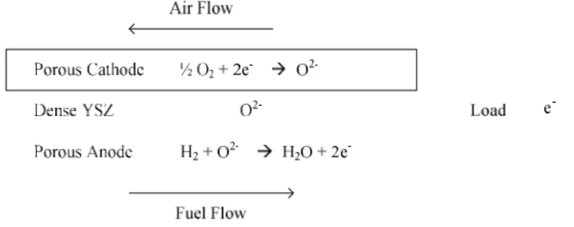
固態氧化物燃料電池(SOFC, solid oxide fuel cell)使用具有氧離子穿透能力的氧化物為固 態電解質,兩側電極分別曝露於燃料氣氛與氧氣氣氛,使氧氣於陰極還原為氧離子並進入電 解質,接著氧離子擴散穿過電解質,最後在電解質與陽極界面氧與燃料於進行電化學氧化,
據以將化學能轉化成電能[1]。
圖 3.1、固態氧化物燃料電池的示意圖
固態氧化物燃料電池的電解質為一種具有高的氧離子穿透率的材料,氧離子經由氧化物
內部的格隙(vacancy)傳遞,因此材料具有離子導電性。固態氧化物燃料電池的構造與氧氣感 測器相似,如圖 3.1 為一個以氫氣為燃料的固態氧化物燃料電池的結構示意圖,以及各部位 進行的反應,於陰極與電解質的界面氧氣分子(O2)取得電子而還原成氧離子(O2-),氧離子(O2-) 穿透過電解質之後於陽極與電解質的界面進行氧化反應,並依據陽極的氣氛形成氧氣分子 (O2)、水(H2O)或二氧化碳(CO2)。
燃料電池於陰極與陽極間產生之電位差(E)可依據 Nernst 方程式得到理論值,當使用氫 氣為燃料時可以式(3.1)表示:
E = E
0+
* 2F
RT ln { P(H
2 anode)*P(O
2 cathode)
1/2/ P(H
2O
anode) }
(3.1)其中 E0為整體反應自由能與標準自由能之差值,R 為氣體常數,T 為系統溫度,F*為法
拉第常數,P 為各項氣體分壓 [1]。
然而實際可以使用的電壓低於理論電壓值,這是由於燃料電池於數個部位產生阻抗造成的 結果。燃料電池實際產生之電壓如同式(3.2):
E = E
eq–E
L– η
act–η
iR- η
diff (3.2)其中 Eeq為理論電壓、EL為電解質漏電損耗、ηact為於電極界面活化反應速度限制損耗、
η
iR為電池電阻、ηdiff為氣體擴散限制損耗。上述各項損耗都會降低電池效能,需要針對成因一一改善。本子計畫研究的陽極部分於此處需要具有高的界面活化反應以便減少
η
act、良好的透氣率以減少
η
diff、並具有低電極電阻與低接觸電阻,因而計畫中陶金電極之組成與微結構與需能提供這些特性。
由於氧氣、燃料與產物氣體都需要在界面參與電化學反應,將燃料與氧氣流體傳輸至反應 界面,以及將產物氣體輸送離開反應界面的流體輸送行為會影響燃料電池的有效反應物濃度,
如果受到傳輸限制造成了高的濃度極化電阻(concentration polarization resistance),將進而影響 輸出功率。為了使上述流體的輸送不受阻礙,電極必須具有孔隙結構,因此電極的製程必須能 保留孔隙。如圖 3.2 為多孔性鎳-釔安定型氧化鋯(Ni-YSZ)電極與釔安定型氧化鋯電解質局部 放大的示意圖,氣隙-電極-電解質三相界面提供電化學氧化反應,以及氧離子、電子、氫氣與 水氣傳輸路徑。純金屬鉑(Pt)、鎳(Ni)等廣用於燃料電池的電極,為了形成多孔性結構發展了 數種製造技術。鉑電極可以以鉑膠為原料,將它塗佈於電解質表面,經由高溫處理將有機物氧 化分解,留下具孔隙結構的金屬電極。多孔性鎳電極製作以含有氧化鎳(NiO)的粉末為原料,
經由塗佈於電解質表面以及高溫燒結,並予以於還原環境形成金屬狀態。通常鎳電極並不單獨 使用,而是與安定型氧化鋯混合形成多孔性陶金電極,氧化鋯粉末的混摻除了應用其電化學特 性之外,還提供骨架以維持電極的多孔性結構。
YSZ H2 Ni
H2O
e’
O2-
圖 3.2、三相界面示意圖
陶金為由金屬相與陶瓷相混合的複合材料,而於燃料電池中的陶金電極需尚需提供三項功 能(1)相連續的金屬相以便導通電子,(2)其與電解質間需形成三相界面以便參與反應的三種粒 子相接觸,(3)金屬相與陶瓷相混合以提供金屬相於高溫之穩定度[2]。傳統電極金屬使用具有 高電化學氧化還原活性的鉑(Pt) [2],於高溫環境操做的燃料電池可使用鎳(Ni)為陽極電極的金 屬相 [2,3-7]。由於需要三相界面與透氣性,傳統電極使用厚膜印刷再加以燒結形成,所以耗 用貴金屬材料多。另一方面,未來元件微小化將需求新的材料組成與微結構搭配,而微小化過
程中可能遇到因電極減薄造成有效三相界面減少的問題,使電池極化損耗變高[8]。跟據文獻 [9,10]的研究,如果增加單位區域三相界面,將可補償因厚度減少造成的極化損耗。本實驗室 先前於研究氧氣感測器時開發了以薄膜技術製做多孔性鉑電極的技術[11],可以形成具有奈米 孔隙純金屬薄膜,本計畫則進一步將此技術應用於製成多孔性陶金電極,並製成固態氧化物燃 料電池與量測特性,並與傳統厚膜技術製作的電極比較。
4、研究方法
4.1. Ni-YSZ、Ni-CeO2-YSZ 薄膜陶金電極研製
本計畫使用反應式共濺鍍與熱還原程序形成多孔性 Ni-YSZ 或是 Ni-CeO2-YSZ 陶金陽極。
共濺鍍系統如圖 4.1 [12]所示:以兩支陰極分別濺鍍鎳靶材與鋯釔混合靶,或是鎳靶材與鋯釔 鈰混合靶,濺鍍過程中通入氬氣與氧氣以形成複合氧化物膜,基座並加以旋轉以便形成均勻 成份與厚度的膜,以及將基材座加熱以增加膜與基材界面的附著力。
Rotation
Gas in To pump
DC RF
M YSZ
圖 4.1. 共濺鍍系統示意圖[12]
再將濺鍍所得之複合氧化物薄膜置於石英管爐中,於真空環境中熱還原或是於稀氫氣氛中熱 還原,使複合氧化物薄膜中的氧化鎳還原成鎳,但保持釔安定型氧化鋯或是鈰摻雜釔安定型 氧化鋯為氧化物狀態。
4.2. 固態氧化物燃料電池
燃料電池元件採用陰極-電解質-陽極的三明治式結構,於 8YSZ 碟型基材兩側分別鍍上陽 極與陰極,再濺鍍薄的白金網罩以提高電子流分散與收集能力。陰極製作方式為將錳酸鍶鑭 (La0.7Sr0.3MnO3) 以網印方式塗佈至 8YSZ 基材上,再予以燒結形成;陽極則採用段落 4.1 之 反應式共濺鍍再加熱還原程序製做多孔性 Ni-YSZ 或是 Ni-CeO2-YSZ 陶金。本計畫也製備使 用厚膜 Ni-YSZ 陽極之燃料電池參考品,以及製作三層薄膜陽極的試片以進行燃料電池效率 比較。
形成燃料電池所需之碟型釔安定型氧化鋯電解質採用陶瓷燒結製作,選用含 8 mol%Y2O3
的 ZrO2(8YSZ)為電解質成份,將採購來之粉末置於不銹鋼模具並以萬能試驗機施壓成碟型基
材,再置於高溫爐中於 1500°C 燒結三小時,待爐冷至室溫後取出。
本計畫建立單氣室式系統與雙氣室系統量測電池之極化曲線,於 700°C 至 800°C 間採用混 合氣(CH4:Air=29.4:70.6)外加約 3%水氣量測,或是以氫氣為燃料,量測並分析電池的最大輸 出功率。
4.3.電極材料分析
電極材料結構以 X 光繞射儀(XRD)分析,表面型態以掃瞄式電子顯微鏡(SEM)觀察,厚度 以表面輪廓儀掃瞄獲得。
5. 結果與討論
本計畫執行期間先以 Ni-YSZ/YSZ/LSMO 固態氧化物燃料電池為基礎,建立多孔性薄膜電極
以及燃料電池元件製程技術平台,並使用於 Ni-CeO2-YSZ/YSZ/LSMO 固態氧化物燃料電池,
以及嘗試製作 Ni-Cu-CeO2-YSZ 電極。本計畫之燃料電池量測方式依序建立單氣室式量測系
統,以及單氣室式量測系統兩項實驗相關技術,並據以量測平面型固態氧化物燃料電池元件,
以及本子計畫發展的多孔性陶金薄膜應用於陽極固態氧化物燃料電池之特性。
5.1. 多孔性 Ni-YSZ 陶金薄膜製程技術平台開發
本研究應用薄膜技術形成具有奈米尺度結構的金屬—陶瓷—孔隙混合結構體,且各別成 份都為連續網狀結構,以便提高電極—電解質—氣體相交之三相界面。多孔性 Ni-YSZ 陶金 薄膜的製作流程設計為鍍膜、結晶化、還原暨孔隙化三個步驟,經由實驗結果得到較佳化參 數,製程技術平台以及較佳參數如圖 5.1,此開發技術使用於本計畫之 Ni-YSZ 與 Ni-CeO2-YSZ 系列陶金薄膜製作。
NiO-YSZ 共濺鍍
NiO-YSZ 結晶化
Ni-YSZ 成型
900°C, 空氣, 1.5 h 800°C, 真空, 1.5 h 350°C, 3 rpm
圖 5.1、陶金薄膜的鍍膜、結晶化、還原流程與較佳製程參數
5.2. 燃料電池元件製作流程
本計畫發展適用於燃料電池的多孔性陶金薄膜,因此需製作完整的燃料電池元件以測試 發電功能。本計畫以量測電池的電壓—電流曲線驗證燃料的電極效能,並於計畫進行中分數 個階段逐步獲得適用的多孔性陶金薄膜,並與傳統厚膜陽極比較,未來將再搭配薄膜電解質 以便得到高輸出功率的燃料電池。由於燃料電池為由三層物質構成,製作過程需考慮製程與 材料整合,而於電極支撐型與電解質支撐型的燃料電池需發展個別的整合製程。圖 5.2 為以 YSZ 電解質為支撐基材,於其兩面依序製備厚膜 LSMO 陰極以及薄膜 Ni-YSZ 陽極的製作流 程與較佳參數,其中各步驟溫度由設計高至低,以維持各個材料於製程步驟中的高溫度仍具 有穩定性,最低溫度(800~900 °C)與最後步驟製程為 Ni-YSZ 薄膜的結晶化與還原孔隙化。而 於製做厚膜陽極的燃料電池參考樣品時,由於 NiO-YSZ 厚膜需要高溫燒結,因此改採取如圖 5.3 的流程,先製作 NiO-YSZ 然後製作 LSMO,於最後步驟才將 NiO-YSZ 以稀氫氣還原成為 Ni-YSZ。
YSZ disc 製作
LSMO 陰極厚膜
LSMO 燒結
NiO-YSZ 薄膜
Ni-YSZ 成型 1500°C
空氣 ,3hr
1100°C 空氣 ,2hr
900°C,空氣 ,1.5hr 800°C,真空 ,2hr 圖 5.2、電解質支撐以及陶金薄膜陽極的燃料電池製作流程與較佳製程參數
YSZ disc 製作
LSMO 陰極厚膜
LSMO 燒結 NiO-YSZ
厚膜
Ni-YSZ 成型 1500°C
空氣 ,3hr
1100°C 空氣 ,2hr
800°C 稀氫氣 ,2hr NiO-YSZ
燒結 1350°C 空氣 ,2hr
圖 5.3、電解質支撐以及陶金厚膜陽極的燃料電池製作流程與較佳製程參數
於電極支撐的燃料電池部分目前研究陰極支撐型,採用 YSZ 與 LSMO 混合基材,於較 低溫度製程以避免兩個材料反應形成高阻抗相,其整合製程流程如圖 5.4,依序於陰極基材上 沉積 YSZ 電解質薄膜與 NiO-YSZ 薄膜,最後形成燃料電池元件。
LSMO-YSZ disc製作
YSZ 濺鍍薄膜 LSMO-YSZ
燒結
NiO-YSZ 濺鍍薄膜
Ni-YSZ 成型 1100°C
空氣 ,2hr
900°C 空氣 ,1.5hr
800°C 稀氫氣 ,2hr NiO-YSZ
結晶化 350°C
3 rpm
350°C 3 rpm
圖 5.4、陰極支撐的燃料電池製作流程與較佳製程參數
5.3. 單氣室式燃料電池量測系統建立
本子計畫為了測試所發展的多孔性陶金薄膜用於燃料電池的性能,乃做成平面碟型的燃 料電池,並以掃瞄電流量測電壓的方式分析燃料電池。雖然高效率的燃料電池採雙氣室式量 測,但由於所需的高溫封合技術不易,因此本研究乃以先以單氣室式量測。單氣室式量測乃 將燃料電池置放於一個混合燃料與空氣的氣氛中,並控制於穩定的高溫環境操作,因此我們 將所製成的燃料電池置於如圖 5.5 的石英載具,再放置於石英管爐中操作。燃料電池的陰極 與陽極分別於兩個面,並以金導線連接至真空電極連接頭(Vacuum feedthrough),再經空氣端 接頭連接至電源電表,為了固定導線並避免短路,乃以中間設計好開口之 S310 不銹鋼製具以 及雲母片固定碟型燃料電池。整組石英載具連同導線接頭設計為獨立組件,可以由管爐側面 接頭伸入爐體中央進行恆溫與變溫之電流量-電壓量測。
圖 5.5、單氣室式燃料電池量測使用之石英支撐管與載具
5.4. 雙氣室式燃料電池量測系統建立
圖 5.6、(a)雙氣室式燃料電池量測系統與(b)不銹鋼製電池載具
本計畫進行於第三年度自行裝設了雙氣室式燃料電池量測系統,以便研究所開發之多孔性
Ni-YSZ 陶金薄膜用於以氫氣為燃料的燃料電池。圖 5.6(a)為一個小型雙氣室式燃料電池量測
系統,使用圓柱型不銹鋼為腔體,一端通入 Ar-20%H2 氣體為燃料,另一端直接接觸空氣,
整個不銹鋼載具置入小型高溫爐體中以保持恆溫之量測條件。碟型燃料電池需固定於如圖 5.6(b)的不銹鋼載具中,為了避免陰極與陽極經由固定不銹鋼載具的螺絲相連通而使電池短 路,固定碟型燃料電池時還需要以中間保留開口的雲母片隔開燃料電池任一個電極與不銹鋼 載具底面。
5.5. 多孔性薄膜 Ni-YSZ 結構控制
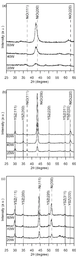
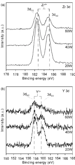
本研究開發以共濺鍍法與後續熱處理方式形成多孔性陶金薄膜,首先以 Ni-YSZ 為材料 系統測試製程平台,於個別步驟時薄膜的組成與表面型態如以下的 XRD 與 SEM 圖。圖 5.7(a) 為於混合氬氣與氧氣氛下以 RF 100 watts 濺鍍 Zr-Y 靶,以及以 DC 20~60 watts 濺鍍 Ni 靶所 得到薄膜的 XRD 分析,其中 NiO 為結晶相,但無法鑑別 YSZ 成份。試片經過 900°C 空氣中 退火之後的 XRD 分析如圖 5.7(b)所示,此時除了 NiO 的結晶相之外,也可見到 8YSZ 形成結 晶相。因此剛濺鍍出來的薄膜中雖然為由結晶狀態 NiO 與非結晶狀態的 YSZ 混合組成,這種 結晶相與分結晶相混合的原因仍未知,但由於陶金電極中的 8YSZ 需為結晶狀態以促進離子 傳導性,因此本計畫試片皆經過此道 900°C 空氣中退火步驟來促進 8YSZ 形成結晶,以便提 高 Ni-YSZ 陽極性能。
圖 5.7、NiO-YSZ 膜於(a)鍍膜與(b)結晶化之後的 XRD 圖譜
經過空氣中退火的 NiO-YSZ 薄膜再於真空環境以 800°C 還原後的 XRD 分析如圖 5.8 所 示,其中 YSZ 仍保持為氧化物結晶相,但 NiO 相消失且轉變成為純 Ni 結晶相。由以上分析 可知經由規劃的兩道熱處理步驟,NiO-YSZ 薄膜已經轉變成為 Ni-YSZ 陶金薄膜。
圖 5.8、真空還原所得陶金薄膜的 XRD 圖譜
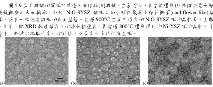
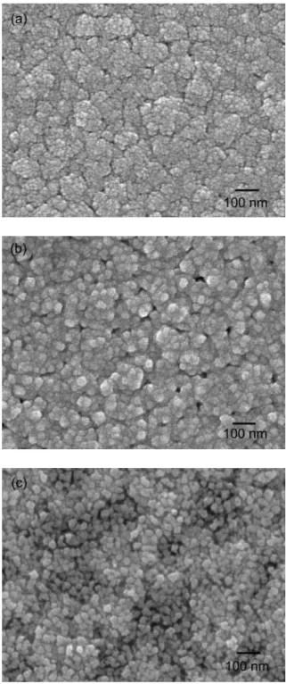
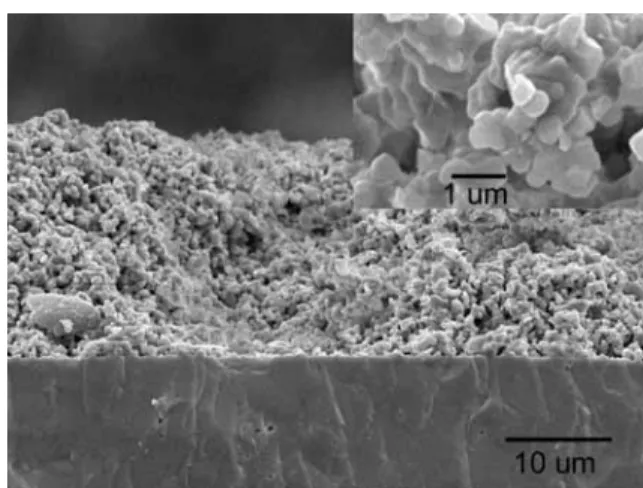
圖 5.9 為共濺鍍的薄膜於前述三個階段(剛濺鍍、空氣退火、真空熱還原)以掃瞄式電子顯 微鏡觀察之表面輪廓,初始 NiO-8YSZ 鍍膜為細小顆粒聚集成類花椰菜(cauliflower-like)結 構,符合一般低溫鍍膜的表面型態。經過 900°C 空氣中退火的 NiO-8YSZ 膜的晶粒長大至數 十奈米,與 XRD 較佳結晶化的結果相穩合。再經過 800°C 還原得到的 Ni-YSZ 膜的晶粒尺寸 縮小,同時出現數十奈米的孔隙,成為奈米多孔性陶金膜。
(a) (b) (c)
圖 5.9、NiO-YSZ 薄膜於(a)鍍膜、(b)結晶化與(c)還原成 Ni-YSZ 的表面型態
經由圖 5.8 的 XRD 分析與圖 5.9 的表面型態分析,我們可以由所規劃的材製料程獲得具 有奈米尺度孔隙的 Ni-YSZ 陶金薄膜,並可以於計畫中用於燃料電池的陽極。因此我們已建
立奈米尺度多孔性陶金薄膜的製程平台,此製作方式也用於開發未來將延續至 Ni-YSZ-CeO2
奈米多孔性陶金膜,應用於燃料電池的陽極。
5.6. 平面型燃料電池之單氣室量測
本計畫以開發薄膜陽極為目標,並將薄膜陽極用於 Ni-YSZ/YSZ/LSMO 燃料電池元件測 試,同時另以使用厚膜 Ni-YSZ 陽極的燃料電池為參考樣品,將兩個樣品以相同量測條件比 較。圖 5.10 為兩個燃料電池的 V-I 與 P-I 曲線,樣品於單氣室式系統通入 29.4 sccm CH4與 70.6 sccm Air 以及約 3%水氣量測,量測溫度介於 600°C 與 800°C 之間,而此處比較的數據為於 700°C 量測的樣品。本研究中以單層薄膜 Ni-YSZ 為陽極的燃料電池之最大輸出功率為 0.38 mW cm-2,而以厚膜 Ni-YSZ 為陽極的參考樣品為 0.76 mW cm-2。初步得到的結果驗證以本計 畫規劃的薄膜陶金陽極可進行電化學氧氣還原反應,且應用於單氣室式量測環境中具有觸媒 選擇性,可促成 CH4與 H2O 重組為 CO 與 H2燃料,並進行電化學氧化反應,促成燃料電池 輸出電力。另一方面,單層薄膜 Ni-YSZ 比厚膜 Ni-YSZ 電極的輸出功率低,其原因仍待探討。
圖 5.10、以 Ni-YSZ 薄膜(●)與厚膜(▲)為陽極之燃料電池於單氣室與甲烷燃料的 V-I 與 P-I 分析
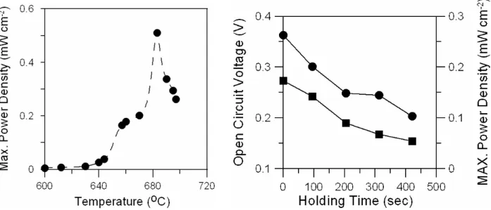
本計畫另以一個三層薄膜陽極的燃料電池試片進行溫度與時間變化對電池效能之影響,
結果如圖 5.11。於 600°C 至 800°C 區間量測電池之 V-I 曲線,再經計算所得的 P-I 曲線中所求 得最大功率密度隨溫度變化的情形,約於 680°C 達到最高的 0.51 mW cm-2,升高溫度則造成
功率密度下降。再升高至 700 °C 持溫量測時,最大功率密度與開環電壓皆隨時間進行而迅速 降低,功率密度於 7 分鐘內由 0.26 mW cm-2降至 0.1 mW cm-2,開環電壓由 0.27 V 降至 0.15 V。
因此可知單氣室式量測系統的參數範圍非常窄,且接近 700 °C 將會因為陽極可能表面碳化阻 礙電池作用。另一方面,經由調整水氣比例於長時間操作燃料電池試片,發現三層薄膜陽極 試片最高輸出可達 1.4 mW cm-2,但是輸出功率於 0.6 mW cm-2與 1.1 mW cm-2之間來回振盪。
由於 Ni 於 700 °C 以上為極佳的碳化觸媒,因此未來可以添加 Cu 與 CeO2來防止碳化反應,
並搭配已發展的多孔性陶金薄膜技術,以及將電解質薄膜化來共同研發高效率燃料電池。
圖 5.11、以三層 Ni-YSZ 薄膜為陽極之燃料電池於單氣室與甲烷燃料的量測所得的最高功率密度與操作溫度及 持溫時間關係
5.7. 平面型燃料電池之雙氣室量測
本研究於第三年度建立雙氣室量測系統,同時也以比較穩定的 Ni-YSZ-CeO2奈米多孔性
陶金薄膜為陽極。,圖 5.12 為電解質支撐型的 Ni-CeO2-YSZ/YSZ/LSMO 燃料電池元件於雙 氣室量測系統,於 800 °C 持溫量測得到的 V-I 與 P-I 曲線,其最大輸出功率約為 6.6 mW cm-2, 大於以 Ni-YSZ 厚膜為陽極的參考燃料電池(~5.0 mW cm-2)。由於薄膜陽極的厚度小於 1μm,
遠小於厚膜陽極約 25 μm的厚度,未來以本研究開發的奈米多孔性陶金薄膜將可以以經濟性
及較高效率的方式,應用於固態氧化物燃料電池。
0 10 20 30
Current Denisty (mA/cm2) 0
0.4 0.8 1.2
Voltage(V)
0 2 4 6 8
PowerDensity(mW/cm2) Thin Anode Thick Anode
圖 5.12、以 Ni-YSZ 薄膜(●)與厚膜(▓)為陽極之燃料電池於雙氣室與氫氣燃料的 V-I 與 P-I 分析
5.8. 鎳奈米線成長
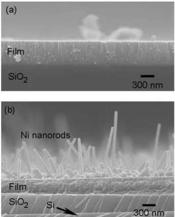
圖 5.13、於 NiO-YSZ 薄膜表面形成的 Ni 奈米柱
本計畫進行中一方面尋求簡化製程,一方面開發新穎的電極微結構,過程中得到如圖 5.13 的鎳奈米線。此處使用類似圖 5.1 的技術平台,首先以共濺鍍法製作 NiO-YSZ 混合氧化物薄
膜,接著於 Ar-20% H2氣份中熱處理,結果於薄膜表層成長出鎳奈米線。此處的鎳奈米線可
能尚無法直接應用於燃料電池的電極,但是預期與總計畫主持人周振嘉教授發展的 YSZ 奈米 線整合之後,便可以做為高效率燃料電池的陽極。
5.9. 網狀銅膜
圖 5.14、(a)以熱氧化形成的 CuO 奈米線與(b)還原後得到的網狀銅結構的型態
本計畫尚無法將銅以如圖 5.1 的技術平台製作成多孔性 Cu-CeO2-YSZ 陶金膜,因此構思
其他方式製作銅基的多孔性陶金薄膜。圖 5.14 的掃瞄式電子顯微鏡影像為本計畫開發的另一 種技術平台,以奈米氧化物為原料,再於轉化形成網狀金屬。將來我們將使用此網狀銅金屬 製作銅基的多孔性陶金,並用於燃料電池的陽極。
5.10. 論文發表與專利申請
本計畫部分成果已整理並撰寫為學術論文並投稿與發表於國際學術期刊,參與學生也完 成三份碩士論文以及發表於國內研討會。目前仍有一位同學將再完成投稿國際論文與完成碩 士論文。另一方面,本計畫的部分成果具有潛力提供工業應用,因此目前申請兩篇國內專利,
以及一篇美國專利。上述論文與專利資訊如下:
5.10.1. 專利申請
1. Shyankay Jou, and Dong-Yu Yeh, “Method of Fabricating One-dimensional Metallic Nanostructure”, US Patent Application No. 11939341. [附件一]
2. 周賢鎧,葉東育,「一維金屬奈米級結構的製造方法」,中華民國專利,國立臺灣科技
大學專利申請字號 0960041TW。[附件一]
3. 周賢鎧,廖勝權,「多孔性網狀金屬的製造方法」,中華民國專利,國立臺灣科技大學專 利申請字號 0960072TW。[附件二]
5.10.2. SCI 期刊論文
1. Shyankay Jou(周賢鎧), Dong-Yu Yeh(葉東育), and Ampere Tseng(曾安培), “Nickel Nanorods Produced by Annealing Composite Oxide Films”,
Journal of Nanoscience and Nanotechnology 8 (2008) 1-3. [附件三]
1. Tzu-Hui Wu(吳姿慧) and Shyankay Jou(周賢鎧),“Thin porous Ni-YSZ films as anode for solid oxidefuelcell”, Journal of Physics and Chemistry of Solids (submitted) [附件四]
5.10.3. 研討會論文
1. 吳姿慧,周賢鎧,2005,「以共濺鍍法製備固態氧化物燃料電池之陽極薄膜研究」,中國
材料科學學會,公元 2005 年材料年會論文。
2. 葉東育、吳姿慧、周賢鎧,「以共濺鍍法製備固態氧化物燃料電池之陽極薄膜研究」,論
文編號 TP01043,中國材料科學學會,公元 2006 材料年會論文。
3. 葉東育,王上瑜,周賢鎧,2007,「以共濺鍍法製備固態氧化物燃料電池之鎳-氧化鈰-氧
化鋯複合薄膜之研究」,中國材料科學學會,公元 2007 年材料年會論文。
5.10.4. 碩士論文
1. 吳姿慧,「以共濺鍍法製備固態氧化物燃料電池之陽極薄膜研究」,台灣科技大學碩士論
文,民國 95 年 5 月。
2. 葉東育,「以共濺鍍法製備固態氧化物燃料電池之銅-氧化鈰-氧化鋯與鎳-氧化鈰-氧化鋯
複合薄膜陽極研究」,台灣科技大學碩士論文,民國 96 年 7 月。
3. 廖勝權,「形成多孔性銅之研究」,台灣科技大學碩士論文,民國 97 年 1 月。
6. 計畫成果自評
本計畫目標為研究以薄膜技術製做多孔性陶金材料,以便做為燃料電池之陽極,使用薄膜 技術取代傳統厚膜技術,因此選擇 Ni-YSZ 為電極材料,以便與傳統厚膜電極之性質比較。
本計畫依據計畫內容主要完成項目包含:
1. 開發以薄膜技術與熱處理製做多孔性鎳陽極薄膜(porous Ni)。
2. 以反應式共濺鍍法與熱處理製做奈米晶粒之鎳-安定性氧化鋯(Ni-8YSZ)多孔性薄膜,
並建立為多孔性陶金薄膜技術平台。
3. 以奈米孔隙之 Ni-8YSZ 陽極用於 Ni-YSZ/YSZ/LSMO 燃料電池元件,以單氣室系統以 及以甲烷為燃料進行電池量測,結果驗證本計畫開發之薄膜電極於適當厚度下,電池 輸出之最大功率高於傳統厚膜之 Ni-8YSZ 陽極。
4. 以奈米孔隙之 Ni- CeO2-8YSZ 陽極用於 Ni- CeO2-YSZ/YSZ/LSMO 燃料電池元件,以 雙氣室系統以及以稀氫氣為燃料進行電池量測,結果驗證本計畫開發之薄膜電極之電 池輸出之最大功率高於傳統厚膜之 Ni-8YSZ 陽極。
5. 本計畫也開發鎳奈米柱與網狀銅膜技術,未來將可以應用於燃料電池。
本計畫於 Ni-Cu-CeO2-YSZ 材料系統開發仍然面臨銅材料穩定性的問題,因此未來於銅
基的多孔性陶金膜將以網狀銅膜技術為基礎。
本計畫已建立多孔性陶金薄膜技術平台,目前驗證用於電解質支撐型燃料電池時優於傳 統厚膜陶金陽極。由於燃料電池的效能受到電解質厚度影響,因此未來將發展薄膜之電解質,
結合本計畫開發之多孔性陶金薄膜技術,獲得高發電效率的薄膜型固態電解質燃料電池。
參考文獻
[1] S. H. Haile, “Fuel cell materials and component,”Acta Mater. 51 (2003) 5981.
[2] W. Z. Zhu and S. C. Deevi, “A review on the anode materials for solid oxide fuel cells,”Mater.
Sci. Eng. A 362 (2003) 228.
[3] F. H. Wang, R. S. Guo, Q. T. Wei, Y. Zhou, H. L. Li and S. L. Li, “Preparation of Ni/YSZ anode by coating procipitation method,”Mater. Lett. 58 (2004) 3079.
[4] X. Huang, Z. Liu, Z. Lu, L. Pei, R. Zhu, Y. Liu, J. Miao, Z. Zhang and W. Su, “A Ni/YSZ composite containing Ce0.9Ca0.1O2-δparticles as an anode for SOFCs,”J. Phys. Chem. Solids 64 (2003) 2379.
[5] D. Rotureau, J.-P. Vircelle, C. Pijolat, N. Caillol and M. Pijolat, J. Eur. Ceram. Soc. 25 (2005) 2633.
[6] T. Hibino, A. Hashimoto, T. Inoue, J.-I. Tokuno, S.-I. Yoshida and M. Sano, Science 288 (2031.
[7] D. Kek, P. Panjan, E. Wanzenberg and J. Jamnik, “Electrical and microstructural investigation of cermet anode/YSZ thin film system,”J. Eur. Ceram. Soc. 21 (2001) 1861.
[8] J. L. Hertz and H. L. Tuller, J. Electroceram. 13 (2004) 663.
[9] A. Bieberle, L. P. Meier and L. G. Gauckler, J. Electrochem. Soc. 1486 (2001) A646.
[10] P. Costamagna, P. Costa and V. Antonucci, Electrochim. Acta 43 (1998) 375.
[11] S.Jou and K.C.Hsu,“MesoporousPtElectrodePreparation Using SputterDeposition and Reduction Treatment,”J. Appl. Electrochem., (in revision)
[12] 王貞芮,「添加銅之二氧化矽複合薄膜之研究」,國立台灣科技大學碩士論文 (2005)。
可供推廣之研發成果資料表
■ 可申請專利 □ 可技術移轉 日期:96 年 12 月 31 日
國科會補助計畫
計畫名稱:先進固態氧化物燃料電池材料界面反應與匹配性研究—
子計畫一:以濺鍍法形成陶金電極之微結構與型態研究
計畫主持人: 周賢鎧
計畫編號:NSC 93-2218-E-011-097 NSC 94-2218-E-011-004
NSC 95-2218-E-011-004 學門領域:材料
技術/創作名稱 一維金屬奈米級結構的製造方法 發明人/創作人 周賢鎧,葉東育
中文:
本方法用於形成奈米等級寬度的金屬線,先製作或取得均勻混合的 兩種氧化物,將該混合氧化物於含氫氣氣氛中加熱,使其中一種氧 化物還原成金屬狀態,並具有奈米等級寬度。
技術說明 英文:
Provided is a method to generate metals nanowires. A mixture of oxides is employed as precursor that is heated in a hydrogen-containing atmosphere. One of the oxides in the mixture is reduced to its metal form with a lateral dimension of nanometers.
可利用之產業 及 可開發之產品
燃料電池電極、自旋電子產品、巨磁阻產品、電磁波遮蔽產品、奈 米電子產品、觸媒、感測器
技術特點 奈米結構、整合製程
推廣及運用的價值燃料電池、氣體感測器、觸媒
※ 1.每項研發成果請填寫一式二份,一份隨成果報告送繳本會,一份送 貴單位研
發成果推廣單位(如技術移轉中心)。
※ 2.本項研發成果若尚未申請專利,請勿揭露可申請專利之主要內容。
※ 3.本表若不敷使用,請自行影印使用。
附件一
可供推廣之研發成果資料表
■ 可申請專利 □ 可技術移轉 日期:96 年 12 月 31 日
國科會補助計畫
計畫名稱:先進固態氧化物燃料電池材料界面反應與匹配性研究—
子計畫一:以濺鍍法形成陶金電極之微結構與型態研究
計畫主持人: 周賢鎧
計畫編號:NSC 93-2218-E-011-097 NSC 94-2218-E-011-004
NSC 95-2218-E-011-004 學門領域:材料
技術/創作名稱 多孔性網狀金屬的製造方法 發明人/創作人 周賢鎧,廖勝權
中文:
本發明使用金屬氧化物線或是多孔性金屬氧化物粉末為原料,於含 氫氣氣氛中進行熱處理,形成交聯網狀金屬構造,並具有相連通的 孔隙。
技術說明 英文:
Provided is a fabrication method, which uses oxide wires of few nanometers to hundreds of nanometers in lateral size or porous oxide powders with pores of tens of nanometers as raw materials, to generate interconnected metal networks with continuous pores, after the oxide wires or powders were annealed in an atmosphere containing
hydrogen.
可利用之產業 及 可開發之產品
生物感測器、化學感測器、氣體感測器、藥物釋放載體、氣體吸附 材料之載體、觸媒或觸媒載體、燃料電池電極、散熱基板、太陽能 電池、超級電容
技術特點 奈米結構、整合製程
推廣及運用的價值燃料電池、氣體感測器、觸媒
※ 1.每項研發成果請填寫一式二份,一份隨成果報告送繳本會,一份送 貴單位研
發成果推廣單位(如技術移轉中心)。
※ 2.本項研發成果若尚未申請專利,請勿揭露可申請專利之主要內容。
※ 3.本表若不敷使用,請自行影印使用。
附件二
Nickel Nanorods Produced by Annealing Composite Oxide Films Shyankay Jou1, Dong-Yu Yeh1, and Ampere A. Tseng1,2 *†
1Graduate Institute of Materials Science and Technology, National Taiwan University of Science and Technology, Taipei, Taiwan 10672 ROC
2Department of Mechanical and Aerospace Engineering, Arizona State University, Tempe, Arizona 85287-6106 USA.
Received 20 June 2007; accepted 17 December 2007 __
*Author to whom correspondence should be addressed: E-mail: [email protected]; Fax: (480) 965-1384.
†On sabbatical leave from Arizona State University, Tempe, Arizona, 85287
ABSTRACT
Nickel nanorods have been produced by annealing a dense composite film. The nanorods of 45-140 nm in lateral dimensions and 230-1400 nm in longitudinal dimensions were obtained by annealing NiO-YSZ composite films in H2at 800 °C for one hour. The axis of the nanorods at the
<220> direction was observed. The dense NiO-YSZ composite film was originally created by co-sputtering Ni and Zr-Y-Ce targets in Ar and O2environment at 350C. Reduction of NiOxto Ni nuclei takes place on the surface of the film. The low crystallinity of the original composite film is believed to facilitate the NiO to grow into Ni nanorods on the discrete Ni seeds by diffusion.
Keywords: Nickel; nanorods; nanowire; oxide film; reduction 附件三
1. INTRODUCTION
One-dimensional nanostructures, including nanotubes, nanowires, nanorods and nanocones of diverse materials, have been receiving extensive interest due to their unique properties.1,2 A great many of techniques have been developed to produce a wide range of nano-scaled structures, from carbon nanotubes to oxides and to metallic and semiconductor nanostructures.1-4 Several processes have been developed on producing metallic nanowires and nanorods.1,2 However, these processes involve multiple steps and require many facilities. This paper provides a simple but versatile approach to generate metallic nanorods.
The processes used for producing metallic nanowires or nanorods include using nanoporous materials or carbon nanotubes as templates for growing metallic nanowires,1,2 using a polyol or a micellar medium for forming one-dimensional precursors and then reducing the precursors for making metallic nanowires, using chemical and hydrothermal reduction of precursors in solutions, and using H2 reduction of dry precursors.2 Also, metallic nanowires, especially Zn nanowires, were generated by condensing vapor to solid (VS),5,6 while direct deposition of Ag nanorods was achieved by employing an oblique angle deposition of Ag with self-shadowed effect.7 Furthermore, metal nanowires have been generated by surface treatment of bulk metal. Lee et al.8 treated a W film in a mixture of H2 and Ar at 850 °C to generate W nanowires by means of a self-catalyzed reaction, while trace of O2 would help forming W nanowires, but oxide nanowires would be generated in the presence of O2 gas.9,10 W nanowires were also generated by depositing tungsten oxide above oxide’s decomposition temperature.11
In this paper, as an alternative, we present a simple method in the generation of nickel nanorods without a template or an intermediate step as compared to those techniques discussed above in the forming of metallic nanorods. The Ni nanorods were directly obtained by annealing the NiO-YSZ composite films in H2 at 800 °C. This method is expected to be used to prepare other metallic nanorods, facilitating a variety of applications.
2. EXPERIMENT
The original NiO-YSZ composite film was created by a mixture of NiO and CeO2-doped YSZ, which were deposited on thermal-oxide-coated Si(100) substrates by using reactive co-sputtering of a Ni and a Zr-Y-Ce targets in a gas mixture of argon (10 sccm) and oxygen (10 sccm). Working and base pressures for the sputtering process were 2.4 Pa and 6.7×10⁻⁴Pa, respectively. The composite oxide film was then annealed in 20 vol.% H2-80 vol.% Ar in a quartz tube furnace at 800 °C for 1 h.
H2reduction was employed to convert NiO-YSZ to Ni-YSZ. However, Ni nanorods were produced on surface of the films.
3. RESULTS AND DISCUSSIONS
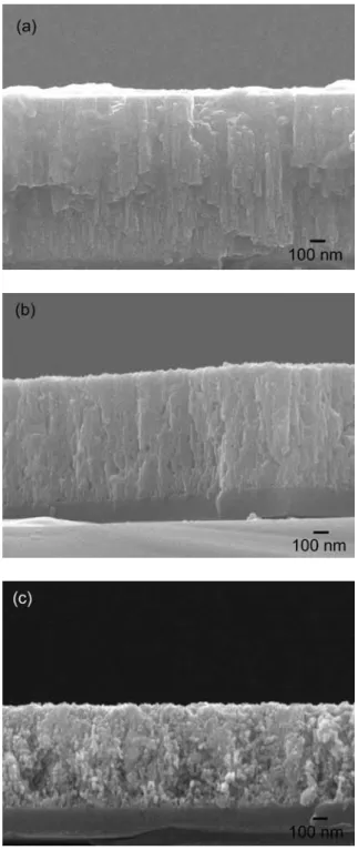
Morphology and structure of the as-deposited (Fig. 1a) and annealed films (Fig. 1b) were first inspected using scanning electron microscopy (SEM). As-deposited composite oxide film has dense columnar structure, as shown in Fig. 1(a), while Fig. 1(b) shows nanorods are grown on the top of a porous film after annealing. These nanorods are 45 to 140 nm in width and 230 nm to 1.4
m in length. Grains of 60 to 200 nm in size are also present on surface of the porous film.
X-ray diffraction (XRD) was also used to study the composition and crystal structure of the nanostructures after and before annealing. XRD spectra were taken at a glancing angle of 5°. As shown in the upper XRD spectra in Fig. 2, the nanorod-containing film is composed of Ni and YSZ phases, while the lower one is the XRD spectra of the as-deposited films. The as-deposited oxide film has low crystallinity, and two broad peaks should represent NiO (111) and (200) reflections in a stressed state. According to the XRD spectra, NiO in the composite oxide film is reduced to form Ni crystals, while the YSZ remains as oxide, after the H2-annealing. Ni nanorods on the surface of
the film are obtained from the oxide film with a relatively low crystallinity
Figure 3(a) presents a TEM image of straight nanorods obtained from above specimen. Figure 3(b) is an enlarged image of a nanorod. Inset in Fig. 3(b) shows an electron diffraction pattern of this nanorod. The diffraction pattern represents [
1 1 2
] zone of Ni cubic crystal with a lattice constant of 0.35 nm. Direction of the [220] (the arrow direction shown in the insert) is parallel to the axis of this nanorod. As a result, nanorods of Ni crystal are produced by annealing aNiO-containing oxide mixture in a H2atmosphere. Reducing NiO to Ni should take place on surface where NiO and H2meet. Ni nuclei are formed on the surface of the film, facilitating subsequent growth of the Ni crystal. Both NiO and Ni clusters are not soluble in YSZ, thus phase separation will occur and NiOxor Ni species will migrate. The as-deposited composite oxide film is uniform and without pore. Reduction would take place when Ni or NiOxdiffuses from inner to free surface of the oxide film.
These largely single-crystal Ni nanorods produced by the present one-step annealing process should have relative low resistivities, less than 10- cm and remarkably high failure density, larger than 108Acm-2.12These Ni nanorods should be an ideal electrode providing necessary electric contact to many different nanodevices for the critic first step towards integration of these
nanodevices. These nanorods should also possess anisotropic magnetoresistance, field emission, quantized conduction and optical limiting properties as those metal nanowires prepared from other processes.2,13-15 Quantification of these material properties is currently under investigation. The effects of the composition of the NiO-YSZ composite films on the geometry, sizes and density of nanorods will also be examined.
4. CONCLUSION
Using an annealing process in a H2atmosphere, Ni nanorods were produced from a NiO-containing oxide mixture. The Ni nanorod is single crystal with growth direction along [220]. It is
believed that reducing NiO to Ni takes place on the surface of oxide mixture and facilitates growth of Ni nanorods. This method should be able to be applied for creating other metallic nanorods and facilitating a variety of applications.
ACKNOWLEDGEMENTS:
This work was supported by the ROC National Science Council through Grant No.
95-2218-E-011-004. National Taiwan University of Science and Technology is acknowledged for providing the University Chair Professorship to the third author during preparing this article. The authors also thank Mr. S. C. Liao for his technical support on transmission electron microscopy.
REFERENCES
1. Y. Xia, P. Yang, Y. Sun, Y. Wu, B. Mayers, B. Gates, Y. Yin, F. Kim, and H. Yan, Adv. Mater. 15, 353 (2003).
2. C. N. R. Rao, F. L. Deepak, G. Gundiah, and A. Govindaraj, Prog. Solid State Chem. 31, 5 (2003).
3. H. J. Fan, P. Werner, and M. Zacharias, Small 2, 700 (2006).
4. A. A. Tseng and A. Notargiacomo, J. Nanoscience Nanotech, 5, 683 (2005).
5. A. Khan, and M. E. Kordesch, Physica E 33, 88 (2006).
6. Y. J. Chen, B. Chi, H. Z. Zhang, H. Chen, and Y. Chen, Mater. Lett. 61, 144 (2007).
7. Y.-P. Zhao, S. B. Chaney, and Z.-Y. Zhang, J. Appl. Phys. 100, 063527 (2006).
8. Y.-H. Lee, C.-H. Choi, Y.-T. Jang, E.-K. Kim, B.-K. Ju, N.-K. Min, and J.-H. Ahn, Appl. Phys.
Lett. 81, 745 (2002).
9. Y. Li, Y. Bando, and D. Golberg, Adv. Mater. 15, 1294 (2003).
10. P. M. Parthangal, R. E. Cavicchi, C. B. Montgomery, S. Turner, and M. R. Zachariah, J. Mater.
Res. 20, 2889 (2005).
11. S. Vaddiraju, H. Chandrasekaran, and M. K. Sunkara, J. Am. Chem. Soc. 125, 10792 (2003).
12. Y. Wu, J. Xiang, C. Yang, W. Lu, and C. M. Lieber, Nature 430, 61 (2004).
13. B. Hausmanns, T. P. Krome, G. Dunpich, E. F. Wassermann, D. Hinzke, U. Nowak, and K. D.
Usadel, J. Magn. Magn. Mater. 240, 297 (2002).
14. K. Nielsch, R. B. Wehrspoon, R. Barthel, J. Kirschner, U. Gösele, S. F. Fischer, and H.
Kronmüller, Appl. Phys. Lett. 79, 1360 (2001).
15. H. Pan, W. Chen, Y. P. Feng, W. Ji, and J. Lin, Appl. Phys. Lett. 88, 223106 (2006).
Fig. 1. Cross-sectional SEM images of NiO-YSZ films (a) before and (b) after annealed in a mixture of H2and Ar at 800 °C for 1 h.
Fig. 2. XRD spectra of mixtures of NiO and YSZ (lower spectra).: the upper spectra are XRD spectra of mixtures of Ni and YSZ obtained after H2annealing.
Fig. 3. TEM images of Ni nanorods.: (a) low magnification; (b) high magnification. Inset in (b) is the diffraction pattern of the Ni nanorod showing [
1 1 2
] zone.Thin porous Ni-YSZ films as anode for solid oxide fuel cell Shyankay Jou* and Tzu-Hui Wu
Graduate Institute of Materials Science and Technology, National Taiwan University of Science and Technology, Taipei 10672, Taiwan, R. O. C.
Abstract
Porous Ni-YSZ films were fabricated by reactive co-sputtering of a Ni and a Zr-Y target followed by sequentially annealing in air at 900 °C and in a vacuum at 800 °C. The Ni-YSZ films
comprised small grains and pores that were tens of nanometers in sizes. The porous Ni-YSZ films were used as the anode on one side of an YSZ electrolyte disc and a La0.7Sr0.3MnO3thick film was used as the cathode on the other side of the disc to form solid oxide fuel cells (SOFCs). The voltage-current curves of the SOFCs with single- and a triple-layered porous anodes were measured in a single chamber configuration, in a mixture of CH4and air (CH4: O2volume ratio = 2:1). The maximum power density of the SOFC using the single-layered porous Ni-YSZ thin films as the anode was 0.38 mW cm-2, which was lower than that of 0.76 mW cm-2, obtained using a
screen-printed Ni-YSZ thick anode. The maximum power density of the SOFC with a thin anode was increased, but fluctuated between 0.6 and 1.14 mW cm-2when a triple-layered porous Ni-YSZ anode was used.
Keywords: Annealing; electrochemical properties; microporous materials; sputtering
*Corresponding author. Tel: +886-2-27376665; fax: +886-2-27301265 E-mail address: [email protected] (S. Jou)
附件四
1. Introduction
Planar solid oxide fuel cells (SOFCs) have been developed for potential use in portable power devices [1-5]. SOFCs have a sandwiched cathode/electrolyte/anode structure. The power
efficiency of fuel cells depends on the resistive and polarization losses that generally are incurred in the fuel cells. Reducing the thickness of the electrolyte increases the power efficiency and reduces the operating temperature of the SOFCs because of the reduction of the resistive loss across the electrolyte [1]. Using a porous cermet electrode with a large three-phase-boundary (TPB) can reduce the loss of activation polarization and improve cell performance [6]. The porous structure of the cermet electrodes facilitates electrochemical reactions at the TPB where the gases, electrolyte and the electrode meet [7]. Conventional SOFCs use dense yttria-stabilized zirconia (YSZ) as the electrolyte, porous nickel (Ni)-YSZ cermet as the anode, and porous strontium-doped lanthanum manganite (LSM) as the cathode [1]. Two stack structures are used in the planar SOFCs [8].
One is that of the electrolyte-supported SOFC and comprises an electrolyte disc of thickness of 50 to 150 μm, with the two sides coated separately with anode and cathode films. The other is that of the electrode-supported SOFC comprising a thick anode or cathode disc with a thickness of a few hundred micrometers, and an electrolyte film with a thickness of 5 to 20 μm.
In electrolyte-supported SOFCs, the thick porous Ni-YSZ anodes are fabricated by the screen printing, tape casting or spray coating of mixtures of NiO and YSZ powders, followed by sintering in air and further reduction in diluted hydrogen [2,4,8,9]. Large YSZ powders are used in the NiO-YSZ ink or slurry to produce a rigid porous microstructure of the Ni-YSZ anode with large grains following sintering. The size of the pores thus produced in the Ni-YSZ anode is in the micrometer range, allowing gases to diffuse through. Yet the Ni-YSZ anode with large YSZ grains reduces the TPB length and causes a loss of electrochemical activity because of the agglomeration of Ni particles at high temperatures [10-12]. The issue of the Ni agglomeration can be minimized by introducing fine YSZ particles in the Ni-YSZ anode [13]. A stable, high-performance porous Ni-YSZ anode has been produced using a mixture of coarse (tens of micrometers) and fine (below one micrometer) particles, to form an entangled YSZ frame and Ni network with large TPB [14].
Various approaches have been employed to increase the TPB and to improve the performance of SOFCs by modifying the porous microstructure with nano-sized substances [15-21]. For instance, cermet anodes can be produced by impregnating a porous Ni frame with ceramic precursors or nano-sized suspensions, or by impregnating a porous YSZ frame with precursors of metal salts, followed by post-annealing [15-17]. A high-efficiency cermet anode with a nano-sized
microstructure can also be obtained by sintering NiO-YSZ core-shell powders [18] or nano-sized composite powders [19-21].
In anode-supported SOFCs, a thick porous Ni-YSZ cermet is employed to provide the mechanical strength for the cell. Slow gas flow through thick Ni-YSZ may cause concentration polarization if the electrode comprises small grains and pores. Multi-layered Ni-YSZ anodes with gradients of composition and microstructure have been used in SOFCs to provide a supporting substrate layer with large grains and pores, and a functional layer with small grains and pores [22-25]. The thin anode functional layer (AFL) comes into contact with the electrolyte and provides abundant TPB. The thick anode substrate layer (ASL) provides high porosity for gas diffusion, thus reducing the concentration polarization. Meanwhile, the ASL contains many large Ni particles to ensure good electrical contact [24]. Anode-supported SOFCs use a thinner
electrolyte than electrolyte-supported SOFCs, which electrolyte has lower resistive loss. Basu et al. [23] studied anode-supported SOFCs with a thin Ni-YSZ AFL of about 5 μm thick and a thick ASL of about 1.5 mm thick. The SOFCs could be operated at an intermediate temperature of under 800 °C by using a 5 μm-thick YSZ electrolyte and a 50 μm-thick LSM cathode on top of the supporting anode.
Dense YSZ electrolyte films with a thickness of under 5 μm have been used in SOFCs, using colloidal spray [26] and various vacuum deposition approaches [27], such as e-beam evaporation [28], sputtering [29-33], pulsed laser deposition (PLD) [5] and polarized electrochemical vapor