A Test-Per-Clock LFSR Reseeding Algorithm for Concurrent Reduction on Test Sequence Length and Test Data Volume
Wei-Cheng Lien and Kuen-Jong Lee
Department of Electrical Engineering National Cheng Kung University, TaiwanTong-Yu Hsieh
Department of Electrical Engineering National Sun Yat-sen University, Taiwan
Abstract
This paper proposes a new test-per-clock BIST method that attempts to minimize the test sequence length and the test data volume simultaneously. An efficient LFSR reseeding algorithm is developed by which each determined seed together with its derived patterns can detect the maximum number of so far undetected faults. During the seed determination process an adaptive X-filling process is first employed to generate a set of candidate patterns for pattern embedding. The process then derives a seed solution that can embed multiple candidate patterns at one time so as to minimize the number of seeds. To shorten the test sequence, the pattern embedding process begins with a small initial set of pseudo-random patterns and will incrementally add more patterns only when necessary. Experimental results show that compared with the previous test-per-clock techniques based on the LFSR- and twisted-ring-counter-reseeding methods, our method can reduce the test sequence length by over 60%
with generally smaller numbers of storage bits. When compared with the mapping-logic-based BIST methods, our method can reduce the test sequence length by over 50% with a comparable area overhead.
1. Introduction
The rapid advances in semiconductor manufacturing technology enable integration of trillions of transistors into a single chip. However, the high chip density also results in large test data volume and long test application time. This can lead to significant increase on the required test cost, especially for the traditional external-tester-based test method [1].
Built-in self-test (BIST) technology that embeds some specific test infra-structure into a circuit-under-test (CUT) is widely adopted to reduce the total test cost.
Most BIST techniques are based on pseudo random testing in which a set of pseudo random test patterns are generated by a linear feedback shift register (LFSR). To overcome the inefficiency problem of pseudo random patterns in detecting random-pattern-resistant (r.p.r) faults, various BIST methods that are capable of applying additional deterministic patterns [2-15] or generate only deterministic patterns [16-18] are proposed. These deterministic patterns can be generated via reseeding [2-5, 10-13, 16-18] or through some additional specific logic such as mapping logic [14-15]. Each seed is then used to derive a sequence of test patterns via LSFR or twisted-ring-counter (TRC) [16-18] operations to cover other faults.
These BIST methods can generally be classified into test-per-scan [2-10] and test-per-clock [11-18] methods according to their test application schemes. The test-per-scan method serially loads one test pattern into scan chains bit-by-bit. The resulting test responses are captured into the scan chains and scanned out for examination. The test-per-clock method applies one test pattern in one test cycle.
All output responses are captured and loaded to a parallel response monitor at each test cycle. Though the area overhead required for the response monitor may be larger, the test-per-clock schemes do have the advantage of much shorter test time since one test pattern can be applied for each clock cycle. In this paper we focus on the test-per-clock BIST method.
Previous reseeding algorithms for the test-per-clock method mainly comprise three steps: seed selection, test sequence generation and test set embedding. The seed selection step usually selects a pattern from a predefined partially-specified test set as an initial seed according to some criterion (e.g., the number of unspecified bits). Then the test sequence generation step derives a sequence of pseudo random or TRC patterns based on the selected seed. The length of the derived test sequence is usually specified as an input parameter for the LFSR-based algorithms and is a fixed value for a TRC-based scheme. The test set embedding step then examines the patterns in the test set one by one to see if each of them can be embedded to one of the generated pseudo random (or TRC) patterns. All patterns that can be embedded are dropped from the test set and all derived pseudo random (or TRC) patterns including the seed are updated. The algorithm is iteratively executed to determine seeds and associated test sequences until all required test patterns are embedded. After determining all seeds, some test-sequence reduction techniques [7-8, 13, 18] can be further employed to reduce the number of generated patterns.
In this paper a new LFSR reseeding algorithm for the test-per-clock method is proposed that attempts to simultaneously minimize both the total number of seeds (test data storage volume) and test sequence length (test application time). Compared with previous test-per-clock methods [11-18], our reseeding technique has the following distinguishing features.
1) Instead of selecting a seed from a predefined test set, our algorithm will determine each seed by starting with a fully unspecified pattern. We will keep as many unspecified bits as possible and will generate a set of candidate patterns for pattern embedding. The seed to generate the pseudo
random sequence will be determined concurrently when all the patterns to be embedded to the seed are determined.
With this method, the determined seeds can generally embed more efficient test patterns.
2) Most previous methods are pattern-count oriented, i.e., during the pattern embedded process, the objective is to embed as many patterns in the original test set as possible.
Our proposed reseeding algorithm is carried out using a fault-count oriented manner, i.e., we will select a set of candidates that are compatible to each other (i.e., can be derived by the same seed) and they together can detect the largest number of undetected faults for each seed. We find that this manner can greatly reduce the number of seeds.
3) Instead of embedding patterns one by one, the proposed pattern embedding procedure attempts to deal with multiple candidate patterns at one time. This can also lead to a significant reduction on the total number of required seeds.
4) Rather than generating a large number of pseudo random patterns at one time for each seed before test embedding process, the proposed algorithm incrementally increases the test sequence length only when necessary such that each seed can be used more efficiently and the test sequence length can be as small as possible.
The experimental results on ISCAS benchmarks show that an average of over 70% reduction on test sequence length can be achieved by our method when compared with other test-per-clock methods using LFSR-based reseeding techniques [12-13]. Also our method requires smaller storage data volume for most large circuits. The comparisons with test-per-clock methods using the mapping logic [14-15]
indicate that our method can save over 50% of test time with a comparable area overhead. We also compare our results with the TRC-based reseeding methods [16-18], and find that 60~99% test sequences reduction can be achieved with smaller storage data volume in most cases.
The rest of this paper is organized as follows. In Section 2 we give some background knowledge for LFSR-based reseeding techniques. The proposed reseeding algorithm to determine the required seeds and test sequences is presented in Section 3. Experimental results are shown and compared with previous work in Section 4. Finally this paper is concluded in Section 5.
2. Preliminaries
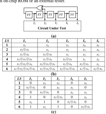
In a test-per-clock BIST scheme, an LFSR is commonly employed as the test pattern generator for the CUT. For each test cycle one pattern is generated, which can be regarded as a state of the LFSR. Consider a CUT that has five input ports I1, I2,…, I5. Fig. 1(a) illustrates an external LFSR with a characteristic polynomial of 1 + x2 + x5. Based on this pre-defined polynomial function, each state and its associated linear equations for each output of the LFSR can be derived [1]. In Fig. 1(b) the equations of the first six states are illustrated. Note that the first state of the LFSR is regarded as the seed. All the required seeds for reseeding can be stored in
an on-chip ROM or an external tester.
(a)
LS I1 I2 I3 I4 I5
1 x1 x2 x3 x4 x5
2 x2⊕x5 x1 x2 x3 x4
3 x1⊕x4 x2⊕x5 x1 x2 x3
4 x2⊕x3⊕x5 x1⊕x4 x2⊕x5 x1 x2 5 x1⊕x2⊕x4 x2⊕x3⊕x5 x1⊕x4 x2⊕x5 x1 6 x1⊕x2⊕x3⊕x5 x1⊕x2⊕x4 x2⊕x3⊕x5 x1⊕x4 x2⊕x5
(b)
LS I1 I2 I3 I4 I5
1 0 x2 x3 0 x5
2 x2⊕x5 0 x2 x3 0
3 0 x2⊕x5 0 x2 x3
4 1 0 x2⊕x5 0 x2
5 x2 1 0 x2⊕x5 0 6 1 x2 1 0 x2⊕x5
(c)
Fig. 1. An example of (a) a five-stage external LFSR with a characteristic polynomial of 1 + x2 + x5, the linear equations associated with each output port of the first six
LFSR states (b) before and (c) after updating To embed a partially-specified test cube Pi into the j-th LFSR state LSj, the compatibility of the pattern pair (Pi, LSj) must be checked to see if a feasible solution to the corresponding set of linear equations can be identified. For example, to embed a test cube P1 (10x0x) to the fourth state LS4, the compatibility of P1 to LS4 is checked by solving the following linear equations.
x2⊕x3⊕x5 = 1, x1⊕x4 = 0, and x1 = 0
Since a solution {x1 = 0, x4 = 0 and x2⊕x3⊕x5 = 1} can be identified, the pattern pair (P1, LS4) is said to be compatible, meaning that P1 can be embedded to LS4. When P1 is indeed embedded to LS4, all the LFSR states should be updated based on the solution for the pair (P1, LS4). Fig. 1(c) shows the results after the update, which can then be further checked to see if more pattern can be embedded. If no solution to the linear equations can be identified, the pattern pair (Pi, LSj) is said to be incompatible.
The main objective of our LFSR reseeding algorithm is to determine an appropriate seed for which a short test sequence can be generated to detect a large number of undetected faults.
The proposed reseeding algorithm is described next.
3. Proposed Concurrent Multiple Pattern Embedding Procedure
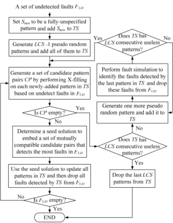
The proposed LFSR reseeding algorithm is outlined in Fig.
2. The input is a testable fault list FT determined from ATPG.
At first, we apply a set of random patterns to identify the set of hard-to-detect faults (or r.p.r. faults) from FT. The identified
faults are recorded in a hard-to-detect fault list FHD.
Fig. 2. Proposed Concurrent Multiple Pattern Embedding Procedure for LFSR Reseeding
We then carry out a seed determination process to generate one seed and derive its corresponding test sequence.
In this process a set of deterministic test cubes will be generated to detect as many faults in FHD as possible. During this process, the compatibility between the test cubes are examined to facilitate the embedding of multiple test cubes into a pseudo-random test sequence at a time. The seed to generate the pseudo random sequence will be determined concurrently when generating these test cubes. Details of this process will be described in the following sub-section. The generated seed is then added to a seed set S and all the detected faults by the derived test sequence are removed from FHD. This process will be executed iteratively until all faults in FHD are detected. Then a seed reusing process is employed to reuse the generated seeds in S to drop detectable faults from FT. In the case that some faults in FT are still undetected after the seed reusing process, some new seeds are generated by the seed determination process again so as to detect all the remaining faults in FT. The pattern embedding procedure shown in Fig.2 will terminate when all testable faults are detected. In the following we give details of the proposed algorithm.
3.1. Seed Determination Process
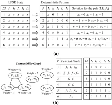
Fig. 3 gives the flowchart of the seed determination process. Based on the undetected fault list FUD, this process generates one seed Snew and its corresponding test sequence TS
aiming to detect as many undetected faults as possible.
Fig. 3. Seed determination process
At first Snew is initialized as a fully-unspecified pattern and is added to TS. Based on Snew we then generate a number of pseudo random patterns and add these patterns to TS. To avoid generating a large number of pseudo random patterns that detect no new faults, a user-defined input parameter LCS (Limit on the number of consecutive redundant patterns) is provided to limit this number. For the first iteration LCS – 1 pseudo random patterns are generated from Snew and TS will contain LCS fully-unspecified patterns. For the following iterations, more pseudo random patterns generated based on the current state of the LFSR are incrementally (i.e., one at a time) added to TS. Each of these patterns will be examined to see if it can detect any new fault. The addition of patterns to TS continues until TS contains LCS consecutive patterns that do not detect any new faults.
When entering the loop on the left-hand-side of Fig. 3, an X-filling process is applied to each newly-added pattern LSi to generate a deterministic pattern Pi. This is done via an ATPG tool by filling some unspecified bits of LSi so as to detect more undetected faults stored in FUD. We then check the compatibility of the pattern pair (Pi, LSi) by solving the corresponding set of linear equations as mentioned in Section 2. If Pi and LSi are compatible, the pattern pair is added to a set of candidate pattern pairs CP. Note that the X-filling process will only consider those faults in FUD that are not detected by the pattern pairs already in CP.
Fig. 4 gives an example to illustrate the seed determination process. Assume LCS is set to 6. Initially a fully-unspecified seed LS1 (x1 x2 x3 x4 x5) and the following five pseudo random patterns LS2, LS3,…, LS6, all also being fully-unspecified at present, are derived. After performing X-filling for each pseudo random pattern to detect some undetected faults, a set of deterministic patterns can be generated as shown in the right-hand-side of Fig. 4(a). We then check the compatibility of each pattern pair and keep the compatible ones as candidate pattern pairs.
For all candidate pattern pairs in CP we then build a compatibility graph as shown in Fig. 4(b). Each node in the graph represents a candidate pattern pair, and a connection line between two nodes represents that the seed solutions associated with the corresponding two candidate pattern pairs are compatible, i.e., a solution exists simultaneously for both candidate pattern pairs. For example, the seed solutions for the pattern pair (P2, LS2) and (P5, LS5) shown in Fig. 4(a) are compatible and can be merged as {x1=1, x2=0, x3=0, x4=0 and x5=1}. This indicates that both test cube P2 and P5 can be successfully embedded to the LFSR states by using the same seed (10001).
Based on the compatibility graph, we determine an optimal seed solution by selecting a set of candidate pattern pairs that can detect the most undetected faults and the seed solutions of these pattern pairs are mutually compatible. To facilitate the pattern pair selection process, we assign a weight to each node (Pi, LSi), which is calculated by summing the number of the new faults detected by Pi and the average number of the new faults detected by the adjacent nodes of (Pi, LSi), i.e., the nodes with a connection line to (Pi, LSi). The middle part of Fig. 4(b) lists the detected faults by each pattern pair in the considered example. It can be seen that the weight of (P1, LS1) is 3 (the number of faults detected by P1) + (2+1)/2 (the average number of detected faults by the two adjacent nodes) = 4.5.
After calculating the weight of each pattern pair, we then select the pattern pair that has the largest weight value and use its seed solution to update the LFSR states. Accordingly the compatible graph can be updated by removing the nodes that becomes incompatible. For the example shown in Fig. 4, we will first select the node (P2, LS2) and update the seed solution to {x1=1, x2=0, x3=0 and x4=0}, which can result in some conflicts between the updated seed solutions and those for the pattern pairs (P1, LS1), (P3, LS3), (P4, LS4) and (P6, LS6). Thus these patterns pairs are removed from the graph. If there are still some unselected nodes in the updated graph, the weight of all remaining nodes will be recalculated by removing those faults which are detected by the selected nodes. For our example, only (P5, LS5) is retained and its weight will be updated to 3. Then, the node with the largest weight will be selected and the current seed solution is again checked and updated accordingly. This step continues until each node in the graph has been selected. In our example, (P5, LS5) can be selected successively and the seed solution of {x1=1, x2=0, x3=0, x4=0 and x5=1} are finally obtained.
(a)
(b)
Fig. 4. An example of the seed determination process to (a) generate a set of candidate pattern pairs, (b) build a compatibility graph of the candidate pattern pairs and
update both the seed and the test sequence
Based on the determined seed solution, the test sequence TS is updated as illustrated in right-hand-side of Fig. 4(b) and all faults detected by the current TS are dropped from FUD. If now FUD becomes empty, the process is terminated. Otherwise a new set of candidate pattern pairs CP is generated via X-filling based on the updated TS and FUD. In the case that no candidate pattern pair can be generated, i.e., CP is empty; we check whether there exist LCS consecutive patterns in TS that do not detect any new faults. If yes, the last LCS redundant patterns in TS are dropped from TS and the process is terminated. Otherwise we incrementally generate more pseudo random patterns based on the last pattern in TS and add them to TS until LCS patterns that do not detect any new faults are in TS. For example using Fig. 4, if the last pattern which can detect faults in the current TS is LS5, 5 new patterns from LS7 to LS11 will be generated and added to TS for candidate pair identification as described before. We then enter the next iteration. Note that only those newly-added patterns in TS, i.e.
LS7 to LS11, will be used for the next iteration.
3.2. Seed Reusing Process
In the seed reusing process we first drop faults in FT (note that FT is different from FUD) that are detected by the test sequences associated with the seeds in S. If now no faults exist in FT, the procedure shown in Fig. 2 is terminated.
Otherwise, we try to reuse the generated seeds by specifying some remaining unspecified bits to drop more undetected faults in FT. We first sort all seeds in S according to the lengths of their derived test sequence. The seed with the smallest test sequence length will be first targeted. A seed determination process as shown in Fig. 3 is executed for the
target seed by employing FT as the input undetected fault list and the test sequence associated with the target seed as the initial test sequence TS. Seeds in S will be taken into account successively according to their sorting order. If some faults in FT are still undetected after considering all seeds in S, the seed reusing process is terminated and new seed(s) and corresponding test sequence(s) will be generated using the seed determination process for the remaining undetected faults.
4. Experimental Results
In this section we provide the experimental results of the proposed reseeding algorithm on ISCAS benchmark circuits and compare the results with related test-per-clock BIST work using reseeding, mapping logic and TRC-based methods. For each experiment an external LFSR is employed for pseudo-random pattern generation. The input parameter LCS (limit on the consecutive redundant patterns) is set to 60. A commercial ATPG tool is employed to execute the X-filling process for 100% test efficiency.
Table 1: Experimental results of the proposed reseeding method for 100% test efficiency
ATPG Test Set Ours CKT #IN |FT| FHD%
#TP smax |S| #TP (BIST)
#Storage Bits RD % c499 41 750 5.87 54 41 4 399 164 92.59 c880 60 942 1.80 31 57 4 511 240 87.10 c1355 41 1566 1.28 84 41 12 908 492 85.71 c1908 33 1870 3.96 116 33 16 1327 528 86.21 c2670 233 2630 12.09 56 200 6 827 1398 89.29 c3540 50 3291 1.34 131 44 8 1378 400 93.89 c5315 178 5293 0.38 72 162 3 826 534 95.83 c7552 207 7419 6.36 98 194 14 1450 2898 85.71
s420 35 430 11.40 49 35 5 393 175 89.80 s641 54 467 3.85 33 53 6 582 324 81.82 s713 54 543 4.24 36 52 5 505 270 86.11 s820 23 850 10.35 100 18 11 1279 253 89.00 s838 67 857 16.92 78 67 12 833 804 84.62 s953 45 1079 11.68 86 44 10 914 450 88.37 s1423 91 1501 3.00 41 89 4 500 364 90.24 s5378 214 4563 3.79 112 204 7 2482 1498 93.75 s9234 247 6475 19.31 153 224 17 2218 4199 88.89 s13207 700 9664 28.39 245 663 6 3418 4200 97.55 s15850 611 11336 8.03 121 584 7 2822 4277 94.21 s38417 1664 31015 10.78 98 1455 8 3939 13312 91.84 s38584 1464 34797 3.87 155 1320 5 4292 7320 96.77 Avg. 89.97
Table 1 shows the overall experimental results of our method. The first six columns show the circuit name (CKT), the number of input ports (#IN), the number of testable faults (|FT|), the percentage of hard-to-detect faults (FHD %), the number of ATPG patterns (#TP) and the maximum number of specified bits in ATPG test set (smax). As indicated, in most circuits smax is very close to #IN. The columns |S|, #TP (BIST) and
#Storage Bits indicate the total number of required seeds, the total number of test application patterns (test sequence length) and the required storage bits (i.e., |S|×#IN), respectively. The last column (RD %) reports the achieved reduction on the storage data volume when compared with the ATPG test set. It
can be seen that our method can achieve 100% test efficiency for all ISCAS benchmarks with a small number of seeds and very short test time. For the largest ISCAS circuit, i.e., s38584, only 4292 test cycles are required to detect all detectable faults.
Table 2 compares the total numbers of storage bits and test patterns between our method and previous LFSR reseeding work [12-13]. In Column Storage Bits the best results are highlighted. As indicated, our method requires the smallest storage data volume for more than half of the CUTs. More significantly, our method requires much smaller numbers of test patterns (or equivalently, test lengths) for all circuits. On average reductions of 72.54% and 82.62% on test sequence lengths can be achieved.
Table 2: Comparisons with LFSR reseeding methods
#Storage bits for seeds #TP (BIST) TP Reduction % CKT Ours [12] [13] Ours [12] [13] ([12]-Ours)
/[12]
([13]-Ours )/[13]
c2670 1398 3029 3510 827 6225 15984 86.71 94.83 c7552 2898 5175 11440 1450 11261 23112 87.12 93.73
s420 175 385 210 393 3450 17676 88.61 97.78 s641 324 216 220 582 1499 3645 61.17 84.03 s713 270 216 165 505 1820 5790 72.25 91.28 s820 253 138 NA 1279 2916 NA 56.14 NA s838 804 1407 871 833 5235 15093 84.09 94.48 s953 450 135 276 914 3159 3975 71.07 77.01 s1423 364 273 NA 500 1457 NA 65.68 NA s5378 1498 856 1935 2482 4222 11808 41.21 78.98 s9234 4199 4940 6696 2218 13785 21731 83.91 89.79 s13207 4200 NA 3505 3418 NA 8550 NA 60.02 s15850 4277 NA 5508 2822 NA 12180 NA 76.83 s38417 13312 NA 34965 3939 NA 34510 NA 88.59 s38584 7320 NA 8790 4292 NA 8052 NA 46.70
Avg. 72.54 82.62
Table 3: Comparisons with mapping-logic-based BIST
Area overhead (gate eqv.) #TP (BIST)
CKT Ours [14] [15] Ours [14] [15]
c880 60 36 NA 511 719 NA
c1355 123 15 NA 908 1186 NA
c1908 132 25 NA 1327 3327 NA
c2670 350 373 508 827 1002 3712
c7552 725 1012 462 1450 3958 8437
s420 44 125 132 393 1876 2568
s641 81 61 67 582 1084 1302
s713 68 59 71 505 1963 1979
s820 63 182 132 1279 498 647
s838 201 423 376 833 1223 1435
s953 113 54 83 914 3147 3114
s1423 91 71 58 500 1102 929
s5378 375 143 97 2482 8469 4763
s9234 1050 948 NA 2218 11207 NA
Total
(c2670-s5378) 2111 2503 1986 11983 24322 28886
In Table 3 we compare the area overhead and test sequence length of our method with those of previous work using mapping logic to generate required seeds [14-15]. The data in the column Area overhead are obtained using the 2-input gate equivalent (GE) method [19]. We calculate the area required to store all the seeds in our method and compare those required for the mapping logic reported in [14] and [15].
The comparisons show that our method can achieve over 50%
reduction on the test sequence length for many circuits with comparable area overhead. Only for the circuit s820 our method needs longer test sequence length. This is due to the fact that s820 has relatively few input ports and a much smaller number of unspecified bits in the test set compared with other circuits.
Table 4 shows the comparisons of our results with the various TRC-based reseeding methods As can be seen, on average 60.99%, 98.44% and 99.24% reductions on the test sequence lengths over [16], [17] and [18], respectively, are achieved by our method. For most of the circuits under consideration including the two largest ones (s38417 and s38584), our method requires smaller test data volume.
However the TRC-based methods do have the advantages of simpler control logic when compared to our method and those in [13-16].
5. Conclusions
Test-per-clock BIST methods have the great advantage of very short test time. In this paper we have developed an efficient LFSR reseeding algorithm for test-per-clock BIST to minimize the number of seeds and the test sequence length simultaneously. Experimental results show that significant reductions on storage data volume and/or test application time are achieved when compared to related test-per-clock BIST methods that are based on LFSR reseeding, mapping logic and TRC reseeding. In fact our method can detect all testable stuck-at faults in any ISCAS circuit in less than 5000 clock cycles.
Acknowledgement: This work was supported in part by the National Science Council of Taiwan under contract numbers NSC 100-2221-E-006-058-MY2 and NSC 100-2218-E-110-001.
Reference
[1] L.-T. Wang, C.-W. Wu, and X. Wen, VLSI Test Principles and Architectures: Design for Testability, Morgan Kaufmann, 2006.
[2] B. Koenemann, “LFSR-coded test patterns for scan designs,” in Proc.
Europe Test Conf. 1991, pp.237-242.
[3] S. Hellebrand, J. Rajski, S. Tarnick, S. Venkataraman and B. Courtois,
"Built-in test for circuits with scan based on reseeding of
multiple-polynomial linear feedback shift registers." IEEE Trans. on Comput., 44(2), pp. 223-233, 1995.
[4] C. V. Krishna and N. A. Touba, “Reducing test data volume using LFSR reseeding with seed compression,” in Proc. Int’l Test Conf., 2002, pp.
321-330.
[5] J. Rajski, J. Tyszer, M. Kassab and N. Mukherjee, "Embedded deterministic test," IEEE Trans. on Computer-Aided Design of Integr.
Circuits and Syst., 23(5), pp. 776-792, 2004.
[6] H.-S. Kim and S. Kang, "Increasing encoding efficiency of LFSR reseeding-based test compression," IEEE Trans. on Computer-Aided Design of Integr. Circuits and Syst., 25(5), pp. 913-917, 2006.
[7] V. Tenentes, X. Kavousianos and E. Kalligeros, “State skip LFSRs:
bridging the gap between test data compression and test set embedding for IP cores,” in Proc. Design Autom. and Test in Europe, 2008, pp.
474-479.
[8] V. Tenentes, X. Kavousianos and E. Kalligeros, "Single and variable-state-skip LFSRs: bridging the gap between test data compression and test set embedding for IP cores." IEEE Trans. on Computer-Aided Design of Integr. Circuits and Syst., 29(10), pp.
1640-1644, 2010.
[9] S. Wang, W. Wei and Z. Wang, "A low overhead high test compression technique using pattern clustering with n-detection test support," IEEE Trans. on Very Large Scale Integr. Syst., 18(12), pp. 1672-1685, 2010.
[10] S. Chiusano, P. Prinetto and H. J. Wunderlich, "Non-intrusive BIST for systems-on-a-chip," in Proc. Int’l Test Conf., 2000, pp. 644-651.
[11] L. Li and Y. Min, “An efficient BIST design using LFSR-ROM architecture,” in Proc. Asian Test Symp., 2000, pp. 386-390.
[12] E. Kalligeros, X. Kavousianos, D. Bakalis and D. Nikolos, "An efficient seeds selection method for LFSR-based test-per-clock BIST," in Proc.
Int’l Symp. on Quality Electronic Design, 2002, pp. 261-266.
[13] E. Kalligeros, D. Bakalis, X. Kavousianos and D. Nikolos,
"Reseeding-based test set embedding with reduced test sequences," in Proc. Int’l Symp. on Quality Electronic Design, 2005, pp. 226-231.
[14] E. Kalligeros, X. Kavousianos, D. Bakalis and D. Nikolos, "On-the-fly reseeding: a new reseeding technique for test-per-clock BIST," Journal of Elect. Testing: Theory and Applications, 18(3), pp. 315-332, 2002.
[15] Y. Si and Z. Zhang, "Multiple test set generation method for LFSR-based BIST," in Proc. Asia and South Pacific Design Autom.
Conf., 2003, pp. 863-868.
[16] K. Chakrabarty, B. T. Murray and V. Iyengar, "Built-in Test Generation For High-Performance Circuits Using Twisted-Ring Counters," in Proc.
VLSI Test Symp., 1999, pp.22-27.
[17] S. Swaminathan and K. Chakrabarty, "On Using Twisted-Ring Counters for Test Set Embedding in BIST," Journal of Elect. Testing: Theory and Applications, 17(6), pp. 529-542, 2001.
[18] B. Zhou, Y.-Z. Ye and Y.-S. Wang, "Simultaneous reduction in test data volume and test time for TRC-reseeding," in Proc. Great Lakes symp. on VLSI, 2007, pp.49-54.
[19] G. De Micheli. Synthesis and Optimization of Digital Circuits, McGraw-Hill, 1994.
Table 4: Comparisons with TRC-based reseeding methods
# Storage bits for seeds #TP (BIST) TP Reduction %
CKT Ours [16] [17] [18] Ours [16] [17] [18] ([16]-Ours)
/[16]
([17]-Ours) /[17]
([18]-Ours) /[18]
s420 175 455 315 NA 393 1378 22365 NA 71.48 98.24 NA
s641 324 594 324 NA 582 1793 35316 NA 67.54 98.35 NA
s713 270 648 432 NA 505 1956 47088 NA 74.18 98.93 NA
s820 253 414 253 NA 1279 1260 11891 NA -1.51 89.24 NA
s838 804 2144 2077 1205 833 6464 280395 101080 87.11 99.70 99.18
s953 450 855 360 351 914 2584 32760 23660 64.63 97.21 96.14
s1423 364 455 NA 824 500 1370 NA 67527 63.50 NA 99.26
s5378 1498 NA 3852 3655 2482 NA 1652508 1031316 NA 99.85 99.76
s9234 4199 NA 12350 9173 2218 NA 6113250 3459060 NA 99.96 99.94
s13207 4200 NA 1400 6707 3418 NA 1961400 1805889 NA 99.83 99.81
s15850 4277 NA 6721 3529 2822 NA 8219783 3174908 NA 99.97 99.91
s38417 13312 NA 31616 30978 3939 NA 105249664 NA NA 99.996 NA
s38584 7320 NA 32208 8769 4292 NA 94337232 8936379 NA 99.995 99.95
Avg. 60.99 96.95 99.24
![Table 4 shows the comparisons of our results with the various TRC-based reseeding methods As can be seen, on average 60.99%, 98.44% and 99.24% reductions on the test sequence lengths over [16], [17] and [18], respectively, are achieved by our method](https://thumb-ap.123doks.com/thumbv2/9libinfo/8997607.284642/6.892.65.831.846.1114/comparisons-results-various-reseeding-reductions-sequence-respectively-achieved.webp)
