行政院國家科學委員會專題研究計畫 成果報告
因應電網智慧化與智慧電動車發展之先進配電系統與技術 研究,--子計畫二:因應電網智慧化與智慧電動車發展之配
電網保護協調技術研究 研究成果報告(精簡版)
計 畫 類 別 : 整合型
計 畫 編 號 : NSC 100-2221-E-011-004-
執 行 期 間 : 100 年 08 月 01 日至 101 年 07 月 31 日 執 行 單 位 : 國立臺灣科技大學電機工程系
計 畫 主 持 人 : 辜志承
計畫參與人員: 碩士班研究生-兼任助理人員:林泊夆 碩士班研究生-兼任助理人員:李育軒 碩士班研究生-兼任助理人員:朱啟瑞
報 告 附 件 : 出席國際會議研究心得報告及發表論文
公 開 資 訊 : 本計畫涉及專利或其他智慧財產權,1 年後可公開查詢
中 華 民 國 101 年 09 月 25 日
中 文 摘 要 : 本文探討如何建立不同形式分散式電源之數學模型,並應用 MATLAB/SIMULINK 建立分散式電源之模型,建立一含有不同 形式之分散式電源與電動車充電站之微電網範例系統,以模 擬微電網在不同運轉模式與運轉條件下之穩態與暫態響應,
並進行故障分析,得知故障發生時各匯流排與線路之故障電 流,將故障分析資料作為第二年計畫之參考依據。
中文關鍵詞: 微電網、孤島偵測、保護協調、智慧型電子裝置、電動車 英 文 摘 要 : This research discusses how to formulate mathematical
models of the different types of distributed generation (DG). MATLAB / SIMULINK is used to implement the established model of distributed generation including Electric Vehicle charging station in the micro-grid system. Therefore, the steady state and the dynamic response of micro-grid under different operating mode can be investigated.
Then, the fault analysis can be carried out to get the fault current information at each bus and line.
The analysis result will be used as reference for the second project.
英文關鍵詞: Microgrid, Islanding Detection, Protection Coordination, IED, EV
行政院國家科學委員會補助專題研究 ■期中進度
□期末報告 -子計畫二:
因應電網智慧化與智慧電動車發展之配電網保護協調技術研究
計畫類別:□個別型計畫 ■整合型計畫 計畫編號:NSC
100-2221-E-011-004
執行期間: 100 年 8 月 1 日至 101 年 7 月 31 日 執行機構及系所:電機工程系
計畫主持人:辜志承 共同主持人:
計畫參與人員:林泊夆、李育軒、朱啟瑞
本計畫除繳交成果報告外,另含下列出國報告,共 ___ 份:
□移地研究心得報告
■出席國際學術會議心得報告
□國際合作研究計畫國外研究報告
處理方式:除列管計畫及下列情形者外,得立即公開查詢
□涉及專利或其他智慧財產權,□一年■二年後可公開查詢
中 華 民 國 101 年 9 月 18 日
附件一
摘要
本文探討如何建立不同形式分散式電源之數學模型,並應用 MATLAB/SIMULINK 建立分散式電 源之模型,建立一含有不同形式之分散式電源與電動車充電站之微電網範例系統,以模擬微電網在不 同運轉模式與運轉條件下之穩態與暫態響應,並進行故障分析,得知故障發生時各匯流排與線路之故 障電流,將故障分析資料作為第二年計畫之參考依據。
關鍵詞(keywords): 微電網、孤島偵測、保護協調、智慧型電子裝置、電動車
Abstract
This paper discusses how to formulate mathematical models of the different types of distributed generation (DG). MATLAB / SIMULINK is used to implement the established model of distributed generation including Electric Vehicle charging station in the micro-grid system. Therefore, the steady state and the dynamic response of micro-grid under different operating mode can be investigated. Then, the fault analysis can be carried out to get the fault current information at each bus and line. The analysis result will be used as reference for the second project.
Keyword: Microgrid, Islanding Detection, Protection Coordination, IED, EV 前言
在過去幾十年裡,電力系統已發展成為集中發電、遠距離輸電的大型互聯網路系統,但近年來用 電負載不斷的增加,而電網建設卻沒有同步發展,使得遠距離輸電線路的輸送容量不斷增大,受端電 網對外來電力的依賴程度也不斷提高,使得電網運行的穩定性及安全性下降。鑒於上述問題,許多國 家如美國、日本、德國、中國等開始研究並應用多種再生能源如煤、石油、天然氣、水力、風力、太 陽能等高效經濟的新型電力技術-分散式電源(Distributed Generation, DG)[1-2]或嵌入式發電(Embedded Generation)。分散式電源一般靠近負載用戶,透過將電能與熱能的利用相結合來提高電能的利用率;
同時,由於發電位置離負載近,還可以提高電力品質與供電可靠性,故分散式電源技術極具發展潛力。
儘管分散式電源優點突出,但存在許多問題,如成本高、控制困難等。為協調分散式電源與主要電網 間的種種問題及分散式電源為電網和用戶所帶來的價值效益,逐步將上述的發展技術加以整合,而有 了微電網(Microgrid)[3-5]此特殊電網形式的概念產生。
國內目前對於微電網之研究尚在起步階段,其研究僅限於太陽能發電與風能之小型微電網電壓與 頻率控制之研究,缺乏自動同步與系統保護之探討[6]。為因應 21 世紀電力系統的革新與發展,以及再 生能源的蓬勃發展,微電網的控制與運轉、保護協調、穩定度及系統最佳化等研究議題,需要積極投 入研究以便與世界各先進國家的技術並駕齊驅,電動車充電站也必須依靠電網智慧化,使系統在供電 時能有效將電力分配,以達到最高之效率。
研究目的
隨著科技高度的發展,電力需求持續的增加,電動車將取代燃機類型汽車,電力網路日益的複雜,
以致於電力系統保護設備及保護方式也隨著科技的進步而推陳出新,但是即使科技再發達,因為機械 設備線路不良、雷擊、人為疏失或其他因素,短路故障的發生仍是無法避免。由於故障發生時會產生 相當大的故障電流,此時保護設備必須快速而安全的動作,將故障的機械或線路設備予以隔離,阻止
供電連續性之目的。
文獻探討
微電網在各國的發展呈現不同特色,有各自的規範及研究,在歐美一些發達國家,微電網的研究 已經取得了更進一步的發展,以下舉數個國家來作探討。
美國 CERTS 於 2002 年提出了微電網概念[8-9],架構如 圖 1。CERTS 所提出的微電網主 要是由容量小於 500kW 的小型分散式電源與負載所構成,並引入了電力電子技術的控制方法,基於此 形成了”隨插即用”[10]的控制思想和設計理念。目前,美國 CERTS 微電網的初步理論研究成果已經在 威斯康辛大學的實驗室平台上得到了成功驗證。自第一個微電網示範工程 MAD RIVER 之後,俄亥俄 州、佐治亞州及加州大學柏克萊實驗室也陸續展開微電網相關的研究。學者們希望進一步的了解微電 網保護和控制策略以及經濟效益等,並初步訂定關於微電網的管理政策和法規,故 IEEE 協調委員會為 此訂定了 IEEEStd 1547,為將來的微電網工程建構其框架。
圖 1 CERTS所提出之微電網架構 圖
1. 再生能源和DG併網技術
近年來歐洲再生能源發展快速,但也面臨能源短缺、對遠東能源進口依賴日益嚴重的問題,且 2008 年歐盟提出「20-20-20」[11]目標後,減碳與增加再生能源導入比例成為強大的壓力。其中「20-20-20」
是指相較於 1990 年水平,至少減少 20%溫室氣體排放量、20%的電力來自再生能源、能源使用上減 少 20%不必要的消耗,以提升能源使用效率。歐盟智慧電網技術平台(European Smart Grid Technology Platform, ETP SmartGrids)先後發表「歐洲未來電網的構想與策略」、「歐洲未來電網策略性研究議程」
與「歐洲未來電網戰略部屬文件」3 份重要文件[12~14],確定今後歐洲智慧電網的發展方向並規劃歐 洲智慧電網發展藍圖。綜合上述 3 份文件,歐盟對智慧電網研發重點為:
2. 電動汽車與電網協調運轉技術
。 3. 電網與用戶的雙向互動技術
。
除了上述國家外,加拿大、澳大利亞等國也展開了微電網之研究。從各國對未來電網的發展策略 和對微電網技術的研究與應用中可清楚看出,微電網的形成與發展絕不是對傳統集中式、大規模電網 的革命與挑戰,而是代表著能源利用意識、環保意識的一種提高與改變,微電網是未來電網實現高效、
環保、優質供電的一個趨勢。
。
研究方法
本研究以 Matlab/Simulink 模擬軟體為工具,在微電網架構下建立微電網範例系統並於未來進行過 電流電驛保護協調的模擬。範例系統中的分散式電源選用了電池儲能與太陽能模型並搭配柴油機等模 型來進行系統的模擬。
一、
風力電機圖 2 為雙饋式風力發電機架構示意圖。風力機是將風能透過風渦輪機轉換為機械能再經由發電 機輸出電能;
電網
控制器
風渦輪機
轉子 風
定子 轉子側
轉換器 定子側轉換器
圖 2 雙饋式風力發電機架構示意圖
圖 3 為利用 Matlab/Simulink 建立應用於本論文範例系統中之雙饋型風力發電模組,由同步發電 機、風渦輪機、定子與轉子轉換器及控制器等所組成。
圖 3 以 Matlab/Simulink 建立雙饋式風力發電機模組
名稱 內容 模組數量 1 額定功率 1.5MVA
電壓 575V 頻率 60Hz 定子電阻 0.00706pu 定子電感 0.171pu 轉子電阻 0.005pu 轉子電感 0.156pu 互感 2.9pu 慣性常數 5.04
極數 3
表 1 雙饋式風力發電機模組參數
二、
太陽能發電圖 4 為太陽能發電系統架構,其中最大功率追蹤演算法可根據太陽照度不同找出最大功率點,
並控制直流/直流升壓轉換器使其能隨時操作在最大功率;轉換器控制需偵測電網之電壓電流,使輸 出電壓得以與電網同大小、同頻率與同相位;太陽能陣列所產生皆為直流電,因此需透過直流/交流 轉換器,變更為交流電後方可與電網併聯供電。
太陽能發電 系統
直流/直流 升壓器
直流/交流 轉換器
最大功率 追蹤
電網
轉換器 控制策略
圖 4 太陽能發電系統架構示意圖
圖 5 為 Matlab/Simulink 下建立之太陽能發電模組方塊圖,由升壓型直流-直流轉換器、變流器與 最大功率追蹤等控制策略所組成。表 2 為本論文應用於範例系統中之太陽能模組相關參數。
圖 5 以 Matlab/Simulink 建立之太陽能發電模組方塊圖
名稱 內容
額定最大輸出功率 75W
額定輸出電流 4.4A
額定輸出電壓 17V
短路電流 4.8A
開路電壓 21.7V
短路電流溫度係數 2.06 (mA/oC) 開路電壓溫度係數 -0.077 (V/oC)
表 2 太陽能模型相關參數
三、
柴油引擎發電機圖 6 為柴油引擎發電機架構圖,主要可分為同步發電機、調速系統與激磁系統三大部分,調速系 統使發電機維持穩定轉速運轉並保持系統頻率穩定;激磁系統可改變激磁電流以維持發電機端電壓。
G
激磁系統 自動電壓調制器
電壓感知器 發電機
場線圈
頻率感知器 負載頻率控制
閥門控制機制 渦輪機
燃料
Pv
∆
Pc
∆
Ptie
∆
PG
∆ QG
∆
圖 6 柴油引擎發電機架構示意圖
1. 同步發電機
三相同步機dq軸轉換等效電路如 圖 7 所示,根據同步機定子繞組、磁場繞組與阻尼繞組之動態 特性,經過派克轉換(Park’s Transformation)將原本三相座標系統轉換為兩相座標(dq軸)系統,可消除動 態方程式之電感、零序等時變參數以利分析。
R
sω
Rλ
qL
lL
mdi
dV
d(a) L′
lkdL′
lfdR′
kdV ′
kdi′
kdR′
fdi′
fdV ′
fdR
sω
Rλ
dL
lL
mqi
qV
q(b)
1
L′
lkq2
L′
lfq 1R′
kq2
V ′
fq 1i′
kq2
R′
fq 2i′
fq 1V ′
kd圖 7 三相同步機(a)d 軸(b)q 軸等效電路 2. 調速系統
調速系統主要提供發電機輸出與頻率控制,使發電機維持穩定轉速運轉並保持系統頻率穩定。
圖 8 是以Matlab/Simulink建立出具等速特性之柴油引擎調速機模型。 圖 9 為具降速特性之柴油引 擎調速機模型。
ACTUATOR
Pmec (pu) 1 TF2
0.0384s+1 1
TF1 0.25s+1 0.009s+1
Product Integrator
1 s Gain K
K
ENGINE CONTROL SYSTEM Td
0.2s+1 0.0002s +0.01s+12
w (pu) 2 wref (pu)
1
圖 8 以 Matlab/Simulink 建立等速特性之柴油引擎調速機模組
ACTUATOR
Pmec (pu) 1
VAR
-C- TF2
0.009s+1 1
TF1 0.25s+1 0.039s+1
Product Integrator
1 s
Gain K2 -K- Gain K
K
ENGINE CONTROL SYSTEM Td
0.1s+1 0.00044s +0.022s+12 w (pu)
2 wref (pu)
1
圖 9 以 Matlab/Simulink 建立降速特性之柴油引擎調速機模組
3. 激磁場系統
當同步發電機負載發生改變時,經由激磁控制系統改變激磁電流以維持其端電壓不變。 圖 10 為 Matlab/Simulink內建之激磁模組,用以表示柴油引擎發電機之激磁系統。
link disabled link disabled
Vf 1
proportionnal saturation
Efd Vtf Ef Vf0 / ka
v0(2)/ka
1/z
1/z Positive Sequence
Voltage Mux f(u)
Main Regulator ka / (ta.s +1)
In Out Low Pass Filter
1 / (tr.s +1) (with IC )
Lead Lag Compensator tc.s+1 / tb.s+1
1+T1s --- 1+T2s
Exciter 1 / (te.s + ke)
In Out
Damping kf.s / (tf.s +1)
In Out vstab
4 vq 3 vd 2 vref
1
圖 10 Matlab/Simulink 內建之柴油引擎發電機激磁模組
四、
電池儲能設備在本文中將利用電池儲能站作為微型電網中之分散型電源,本論文視電池儲能技術已開發成熟,
電池成本不高之情況下,且不將成本考慮至微型電網之研究。
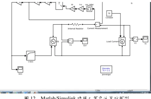
蓄電池模型的概念是以一可控電壓源串聯一內電阻,作為等效的蓄電池模型;而此電壓源的電壓 值是依據蓄電池的殘量所對應到的電壓值來控制。因此除了電路架構外,還須結合另一個控制迴圈來 做計算與控制。蓄電池模型建構示意圖,如 圖 1111 所示。
控制迴圈將蓄電池殘量初始值加上以電流Ib對時間做積分計算之蓄電池電量變化,所得結果為蓄 電池之電量,再以此對應到電壓與電量的關係曲線來控制可控電壓源的輸出電壓值Eb
Ib
Rin SOC V
SOC-V對照 積分器
SOC0
SOC
V
Vb
Eb
∫
。
圖 11 蓄電池模型建構示意圖
利用 Matlab 軟體的 Simulink 介面,依據此概念所建構出之蓄電池等效模型,如 圖 12 所示。在 模擬中先以定電流源作為負載以方便在模擬中控制蓄電池輸出電流。
圖 12 Matlab/Simulink 建構之蓄電池等效模型
五、
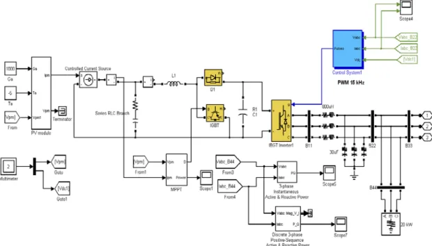
電動車充電站本研究將利用可控式整流器建立電動車充電器之模型,可控式整流充電機主要包含三相交流電 源、功率開關、控制迴路與直流迴路,其架構 圖 13 所示。
- PI +
i*q
vdc
V*dc - + vdc
iabc L
+
RL
iq
PI
PI dq
abc abc
dq
id
i*d -
+
PWM產生器
Ctroller
圖 13 可控整流充電機架構圖
可控整流式,已是許多製作充電機廠家的做法之一。本研究將利用 Matlab/simulink 建立可控整流 充電機模擬。可控整流充電機 Matlab/simulink 整體架構如圖所示。
圖 14 可控整流充電機 Matlab/simulink 整體架構
六、
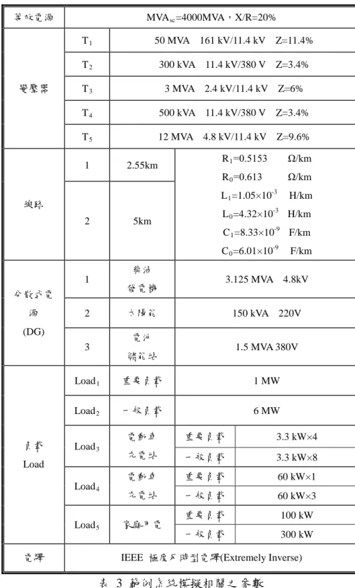
範例模擬系統之建立本文參照台灣電力公司再生能源發電系統併聯要點[15],設計一包含柴油引擎發電機、風力發電機 及太陽能發電模組等 DG 之微電網範例系統,其系統單線圖及參數分別如 圖 15 與 表 3 所示。並應 用 Matlab/Simulink 建構此微電網範例系統,如 圖 15 所示,本計畫未來將利用此範例系統,模擬與 分析此系統分別運轉於(1)併網運轉模式(2)孤島運轉模式時之保護協調。
Battery
#Line1 l=2.55km
Bus 2
#T1 161kV/11.4kV
50MVA Z=11.4%
#T2 11.4kV/380V
200kVA Z=3.4%
PD17 PV
#Line2 l=5km
#T3 380V/11.4kV
3MVA Z=6%
Energy Stroage
#T4 11.4kV/220V
500kVA Z=3.4%
Charging Station II (CS2)
Charging Station I (CS1) PD1
PD5
PD2
PD6 PD7
PD3 PD8 PD4
PD12
PD13
PD16
PD14
PD15 Utility
4000MVA 161kV
Bus 5
Bus 3
Bus 4 Bus 7
Bus 1 Bus 6
Critical Load 3 300kW Diesel Engine
Critical Load 2
1MW Uncritical
Load 1 6MW PD11
PD10
#T5 4.8kV/11.4kV
12MVA Z=9.6%
PD9
AC\DC
Critical Charger 60kW
Uncritical Charger 60kW×3
Critical Charger 3.3kW×4
Uncritical Charger 3.3kW×8
Uncritical Load 4 100kW
圖 15 微電網範例系統單線圖
等效電源 MVAsc=4000MVA,X/R=20%
變壓器
T1 50 MVA 161 kV/11.4 kV Z=11.4%
T2 300 kVA 11.4 kV/380 V Z=3.4%
T3 3 MVA 2.4 kV/11.4 kV Z=6%
T4 500 kVA 11.4 kV/380 V Z=3.4%
T5 12 MVA 4.8 kV/11.4 kV Z=9.6%
線路
1 2.55km R1=0.5153 Ω/km
R0=0.613 Ω/km L1=1.05×10⁻³ H/km L0=4.32×10⁻³ H/km C1=8.33×10⁻⁹ F/km C0=6.01×10⁻⁹ F/km
2 5km
分散式電 源 (DG)
1
柴油
發電機 3.125 MVA 4.8kV
2 太陽能 150 kVA 220V
3
電池
儲能站 1.5 MVA 380V
負載 Load
Load1 重要負載 1 MW
Load2 一般負載 6 MW
Load3
電動車 充電站
重要負載 3.3 kW×4
一般負載 3.3 kW×8
Load4
電動車 充電站
重要負載 60 kW×1
一般負載 60 kW×3
Load5 家庭用電
重要負載 100 kW
一般負載 300 kW
電驛 IEEE 極度反時型電驛(Extremely Inverse)
表 3 範例系統模擬相關之參數 結論
本計畫已建立各分散式電源之模型,如:太陽能發電、風力發電和柴油發電…等,並將其整合至 微電網範例系統中,完成一據有電池儲能站與電動車充電站之微電網範例系統,模擬微電網在併網運 轉與孤島運轉之情況,並對此範例系統進行故障分析,量測各饋線與各匯流排上之故障電流,如三相 短路故障、單向短路故障等,並將模擬之匯流排與各饋線所量測之數據進行分析,以利第二年計畫中 之保護管理系統(PMS)之建立參考數據。
參考文獻
[1] Morren, J., de Haan, S. W. H., and Ferreira, L. A., “Distributed Generation Units Contributing to Voltage Control in Distribution Network,” International Universities Power Engineering Conference, 2004, pp. 789-793.
[2] Macken, K. J. P., Bollen, M. H. J., and Belmans, R. J. M. , “Tigation of Voltage Dips Through Distributed Generation Systems,” IEEE Trans on Industry Applications, 2004, pp. 1686-1693.
[3] Katiraei, F., and Iravani, M. R., “Power Management Strategies for a Microgrid with Multiple Distributed Generation Units,” IEEE Transaction on Power Systems, Nov., 2006, pp. 1821-1831.
[4] Zeineldin, H. H., Ehab F. El-Saadany, and M. M. A. Salsma, “Distributed Generation Micro-Grid Operation: Control and Protection,” Proceeding of IEEE Conference on Power Engineering, 14-17 March, 2006, pp. 105-111.
[5] Katiraci, F., and Abbcy, C., “Diesel Plant Sizing and Performance Analysis of a Remote Wind-Diesel Microgrid,” Proceeding of IEEE Conference on Power Engineering, 24-28 June, 2007, pp. 1-8.
[6] 林群峰,以分散式太陽能發電系統為主之微電網,國立台灣科技大學碩士論文,民國 96 年 7 月。
[7] Robert, H. L.,and Paolo, P., “Extended Microgrid Using Distributed Energy Resources,” Power Engineering Society General Meeting, June, 2007,pp. 1-5.
[8] Lasseter R. H., “CERTS Microgird,” Proceeding of IEEE Conference on Power Engineering, 16-18 April, 2007, pp. 1-5.
[9] Lasseter, R. H. and Paigi, P., “Microgrid: a Conceptual Solution,” Proceeding of IEEE Conference on Power Engineering, Vol. 6, 20-25 June, 2004, pp. 4285- 4290.
[10] Nikkhajoei, H., and Lasseter, R. H., “Microgrid Protection,” Power Engineering Society General Meeting, 24-28 June, 2007, pp 1-6.
[11] http://ec.europa.eu/clima/policies/package/index_en.htm
[12] European Commission, “European SmartGrids Technology Platform,” Vision and strategy for Europe's Electricity Networks of the future, V&S, 2006.
[13] European Commission, “European SmartGrids Technology Platform,” Strategic Research Agenda for Europe's electricity Networks of The future, SRA, 2007.
[14] European Commission, “European SmartGrids Technology Platform,” Strategic Deployment
[15] 郭芳楠、林明民、馮輝正、江榮城,分散型電源倂聯技術要點整合,第二十四屆電力工程研討 會.
國科會補助專題研究計畫成果報告自評表
請就研究內容與原計畫相符程度、達成預期目標情況、研究成果之學術或應用價 值(簡要敘述成果所代表之意義、價值、影響或進一步發展之可能性) 、是否適 合在學術期刊發表或申請專利、主要發現或其他有關價值等,作一綜合評估。
1. 請就研究內容與原計畫相符程度、達成預期目標情況作一綜合評估
■ 達成目標
□ 未達成目標(請說明,以 100 字為限)
□ 實驗失敗
□ 因故實驗中斷
□ 其他原因 說明:
2. 研究成果在學術期刊發表或申請專利等情形:
論文: □已發表 □未發表之文稿 ■撰寫中 □無 專利: □已獲得 □申請中 ■無
技轉: □已技轉 □洽談中 ■無 其他: (以 100 字為限)
附件二
3. 請依學術成就、技術創新、社會影響等方面,評估研究成果之學術或應用價 值(簡要敘述成果所代表之意義、價值、影響或進一步發展之可能性)(以 500 字為限)
微電網可以滿足區域負載的電力需求,區域負載可能為商業區和住宅區,或者是傳統 電力系統供電成本太高或無法到達的區域,相對於傳統的輸配電系統,微電網較為靈活。
可利用微電網之供電模式使發電成本降低並且減少各地區供電不足之情況。本計畫利用 Matlab/Simulink 軟體建立微電網範例系統,以模擬微電網之方式在不同運轉模式以及運轉 條件下之穩態與暫態響應。
未來將開發 IED 硬體裝置,並建立微電網管理系統與保護管理系統,利用微電網管 理系統規劃微電網之線路結構和分散式電源之輸出電能,保護管理系統則規劃微電網之保 護策略,並利用通訊技術(如:IEC-61850)設定各 IED 之相關參數,以達到微電網之保護最 佳化。
國科會補助計畫衍生研發成果推廣資料表
日期: 年 月 日
國科會補助計畫
計畫名稱:
計畫主持人:
計畫編號: 領域:
研發成果名稱
(中文)
(英文)
成果歸屬機構
發明人
(創作人)技術說明
(中文)
(200-500 字)
(英文)
產業別
技術/產品應用範圍
技術移轉可行性及預期 效益
註:本項研發成果若尚未申請專利,請勿揭露可申請專利之主要內容。
附件三
國科會補助專題研究計畫移地研究心得報告
日期: 年 月 日
一、移地研究過程 二、研究成果 三、建議 四、其他
計畫編號 NSC - - - - - 計畫名稱
出國人員 姓名
服務機構 及職稱
出國時間
年 月 日至 年 月 日
出國地點
附件四
國科會補助專題研究計畫項下出席國際學術會議心得報告
日期: 年 月 日
一、參加會議經過
1. 八月二十二日從桃園機場搭乘 23:50 長榮班機飛往法國巴黎。
2. 八月二十三日 10:20 抵達法國巴黎。
3. 八月二十四日早上前往會議地點參加大會開幕儀式,領取會議論文集(光碟片)及議程等相關資料。
參加大會安排的專題演講(場次 B),場次 B 之專題演講討論一些設備感測研究議題。接著參加 Session-1 場次 A 之技術研討會,學生之論文 Research on Transformer Condition-based Maintenance System using the Method of Fuzzy Comprehensive Evaluation 安排在此場次發表(共有 9 篇論文發表),
議程主席為 Dr. Gamail Darwish ,Subhash Chander Sharma,主席及與會人員對本論文極有興趣,提問 一些問題及建議,非常值得參考。
4. 八月二十五日參加大會安排的專題演講(場次 A),場次 A 之專題演講討論一些數學演算法應用在科 學及工程領域上,包括線性規劃、模糊理論、類神經網路及成本最佳化設計等議題,瞭解目前有關 科學及工程領域上數學演算法的應用研究議題。從討論的議題獲得一些新的觀念。
5. 八月二十六日參加大會安排的專題演講(場次 B),場次 B 之專題演講討論目前非常熱門的研究議題
『設備狀態維護』,包括設備狀態監測技術、設備成本、壽命及風險評估等技術的發展,瞭解目前 有關設備狀態維護研究議題。其中有二篇論文研究設備狀態監測及風險評估對電力設備系統的影
計畫編號 NSC100-2221-E-011-004
計畫名稱 因應電網智慧化與智慧電動車發展之配電網保護協調技術研究 出國人員
姓名 林柏君 服務機構
及職稱 台灣科技大學電機系 會議時間
100 年 8 月 24 日 至
100 年 8 月 26 日
會議地點 法國巴黎
會議名稱
(中文)
2011 年國際大學科學工程和技術會議(英文)
INTERNATIONAL UNIVERSITY CONFERENCE 2011發表論文 題目
(中文)
應用模糊綜合評判法於變壓器狀態維護系統的研究(英文)
Research on Transformer Condition-based Maintenance System using the Method of Fuzzy Comprehensive Evaluation附件五
6. 八月二十七日,從巴黎搭乘 11:20 長榮航空班機返國。
7. 八月二十八日,抵達桃園國際機場。
二、與會心得
2011 年國際大學科學工程和技術會議,與會者均為科學工程系統領域之專家、學者及研究人員,
出席情況極為踴躍。此次大會共有 376 篇論文發表,除蒐集到大會之光碟論文資料外,並簡報學 生的研究成果與心得,並聽取專家及學者的意見及建議,實屬極為寶貴之經驗。此外,並可藉由 與國際學者、專家學術交流,對學生後續研究及博士學位之培育有實質的助益。
三、考察參觀活動(無是項活動者略) 四、建議
國外針對『設備狀態維護』已經研究很長時間,並且有許多成功案例,目前國內對於『設備狀態 維護』正在研究起步中,因此建議未來可以朝設備狀態監測技術、狀態維護、壽命及風險評估等 技術進行研究。
五、攜回資料名稱及內容
會議論文集一本與會議論文光碟一片。
六、其他
國科會補助專題研究計畫國際合作研究計畫國外研究報告
日期: 年 月 日
一、國際合作研究過程
(若不只一位研究人員出國,應敘明分工情況及個人角色)二、研究成果 三、心得與建議
四、本項與國外合作研究之性質,屬:(可複選)
□分工收集研究資料
□交換分析實驗或調查結果
□共同執行理論建立模式並驗証
計畫編號 NSC - - - - - 計畫名稱
出國人員 姓名
服務機構 及職稱 出國時間 年 月 日至
年 月 日
出國地點
合作國家 外國合作計
畫主持人英 文姓名
(First Name) (Last Name)
外國合作 機構
註:1.若出國人員不只一位,應分列姓名。2.外國合作機構及主持人應寫全名。
附件六
□共同執行歸納與比較分析
□元件或產品分工研發
□其他 (請填寫) _______
五、其他:
(本項國合計畫若有下列各項情況,但不以為限,請分項敘述說明)(一)除了我方派員前往研究,是否有國外研究人員來台參與研究? 若是,請補充 來台人員姓名、期間及其活動重點。
(二)是否包括年輕研究人員(一般指博士生或博士後研究人員)之培育?
(三)雙方合作成果,是否有與國外共同產生之期刊或會議論文已/擬進行發表?論 文名稱(若已有)為何?
(四)雙方是否已/將有申請共同專利或展開技術移轉之研發成果?若已進行,則擬 申請專利之國家或期間為何?
(五)未來雙方是否有持續合作之規劃?
參加 2011 年國際大學科學工程和技術會議 (INTERNATIONAL UNIVERSITY CONFERENCE 2011)並發表論文
一、參加會議經過
1. 八月二十二日從桃園機場搭乘 23:50 長榮班機飛往法國巴黎。
2. 八月二十三日 10:20 抵達法國巴黎。
3. 八月二十四日早上前往會議地點參加大會開幕儀式,領取會議論文集(光碟片)及議程 等相關資料。參加大會安排的專題演講(場次 B),場次 B 之專題演講討論一些設備感 測研究議題。接著參加 Session-1 場次 A 之技術研討會,學生之論文 Research on Transformer Condition-based Maintenance System using the Method of Fuzzy Comprehensive Evaluation 安排在此場次發表(共有 9 篇論文發表),議程主席為 Dr.
Gamail Darwish ,Subhash Chander Sharma,主席及與會人員對本論文極有興趣,提問 一些問題及建議,非常值得參考。
4. 八月二十五日參加大會安排的專題演講(場次 A),場次 A 之專題演講討論一些數學 演算法應用在科學及工程領域上,包括線性規劃、模糊理論、類神經網路及成本最 佳化設計等議題,瞭解目前有關科學及工程領域上數學演算法的相關應用研究議 題。從討論的議題獲得一些新的觀念。
5. 八月二十六日參加大會安排的專題演講(場次 B),場次 B 之專題演講討論目前非常熱 門的研究議題『設備狀態維護』,包括 設備狀態監測技術、設備成本、壽命及風險評 估等技術的發展,瞭解目前有關設備狀態維護研究議題。其中有二篇論文研究設備 狀態監測及風險評估對電力設備系統的影響,因應電力公司成本考量政策,設備狀 態維護的相關研究議題勢必會愈來愈受到重視。
6. 八月二十七日,從巴黎搭乘 11:20 長榮航空班機返國。
7. 八月二十八日,抵達桃園國際機場。
二、與會心得
2011 年國際大學科學工程和技術會議,與會者均為科學工程系統領域之專家、學者 及研究人員,出席情況極為踴躍。此次大會共有 376 篇論文發表,除蒐集到大會之光碟 論文資料外,並簡報學生的研究成果與心得,並聽取專家及學者的意見及建議,實屬極 為寶貴之經驗。此外,並可藉由與國際學者、專家學術交流,對學生後續研究及博士學 位之培育有實質的助益。
三、
攜回資料名稱及內容
會議論文集一本與會議論文光碟一片。
Paper ID Code: FR81000 (Please accept our apologies for any inconveniences caused &
double entries received) Letter of Acceptance Paris, France August 24-26, 2011
Dear Author,
Herewith, This is kindly to inform you that the peer- reviewed draft paper (see below abstract) has been accepted for oral presentation as well as inclusion in the proceedings of the
conference to be held in Paris, France during August 24-26, 2011. The high-impact conference papers are also considered for possible special journal publication [p-ISSN 2010-376X, e-ISSN 2010-3778] at http://www.waset.org/journals/waset/
Conference Registration Documents:
1. Registration Form File should be Downloaded at http://www.waset.org/downloads/frreg.doc 2. Copyright Transfer Form File should be Downloaded
at http://www.waset.org/downloads/copyright.doc 3. Word Template File should be Downloaded at http://www.waset.org/downloads/template.doc
4. Latex Style File should be Downloaded at http://www.waset.org/downloads/latex.zip
Letter of Invitation and Visa Requirements:
If you need an invitation letter to get an entrance Visa, Please fill in the online form to get a letter of invitation at http://www.waset.org/invitation.php
Online Conference Registration Form:
The Conference Program and Certificate of Presentation will be composed using the data entered through the online author registration form. All the conference registration files should be zipped (.zip) or rarred (.rar) and submitted via online form
at: http://www.waset.org/author.php
Best regards,
WASET
Editor-in-Science
NMSU
Las Cruces, NM 88003-3151 USA
V:++15756350018
PS: Whilst registered to the conference, for unforeseen circumstances, if you can not attend the conference, the final conference paper will be published in the conference proceedings and posted to your postal address.
Conference Venue and Accommodation:
Ms. Christine ALLERY (Service Réservations) Holiday Inn Paris
Montparnasse-Av.Du Maine 79-81 Avenue Du Maine Paris, 75014 France Phone: +33-1-43201393 Fax: +33-1-43209560
www.holidayinn.com/parisgare --- Original Message ---
From: [email protected] To: [email protected]
Sent: Thursday, June 30, 2011 8:41 AM
Subject: Paris_France August11 International Conference on Electrical, Computer, Electronics & Communication Engineering
Paris_France August11 WASET CONFERENCE PAPER Date : 2011-06-29 23:06:50 IP Adress :140.118.207.98
Name
Surname Mr. Po-Chun Lin
Institution Department of Electrical Engineering, National Taiwan University of Science and Technology
Country Taiwan Alternative
[email protected]
Paper Title Research on Transformer Condition-based Maintenance System using the Method of Fuzzy Comprehensive Evaluation
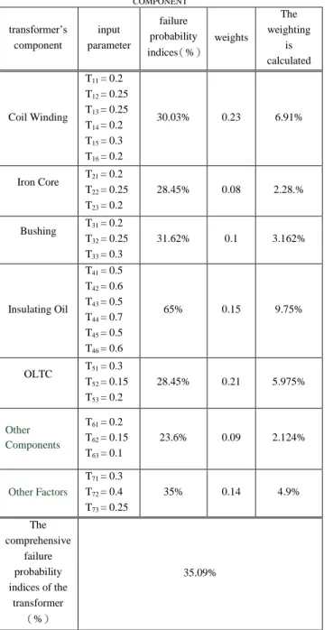
Abstract This study adopted previous fault patterns, results of detection analysis, historical records and data, and experts experiences to establish fuzzy principles and estimate the failure probability index of components of a power transformer. Considering that actual parameters and limiting conditions of parameters may differ, this study used the standard data of IEC, IEEE, and CIGRE as condition parameters. According to the characteristics of each condition parameter, relative degradation was introduced to reflect the degree of influence of the factors on the transformer condition. The method of fuzzy mathematics was adopted to determine the subordinate function of the transformer condition. The calculation used the Matlab Fuzzy Tool Box to select the condition parameters of coil winding, iron core, bushing, OLTC, insulating oil and other auxiliary components and factors (e.g., load records, performance history, and maintenance records) of the transformer to establish the fuzzy principles. Examples were presented to support the rationality and effectiveness of the evaluation method of power transformer performance conditions, as based on fuzzy comprehensive evaluation
Keywords Fuzzy, relative degradation degree, condition-based maintenance, power
Abstract—This study adopted previous fault patterns, results of detection analysis, historical records and data, and experts’
experiences to establish fuzzy principles and estimate the failure probability index of components of a power transformer. Considering that actual parameters and limiting conditions of parameters may differ, this study used the standard data of IEC, IEEE, and CIGRE as condition parameters. According to the characteristics of each condition parameter, relative degradation was introduced to reflect the degree of influence of the factors on the transformer condition. The method of fuzzy mathematics was adopted to determine the subordinate function of the transformer condition. The calculation used the Matlab Fuzzy Tool Box to select the condition parameters of coil winding, iron core, bushing, OLTC, insulating oil and other auxiliary components and factors (e.g., load records, performance history, and maintenance records) of the transformer to establish the fuzzy principles. Examples were presented to support the rationality and effectiveness of the evaluation method of power transformer performance conditions, as based on fuzzy comprehensive evaluation.
Keywords—Fuzzy, relative degradation degree, condition-based maintenance, power transformer
I. INTRODUCTION
ODERM power systems have become increasingly complicated; hence, the reliability of power equipments is directly related to the safe operation of a power system. A large power transformer is one of the main equipments for power system operation. Once a power transformer breaks down, safe operation of the power system will be affected. An evaluation of the power transformer condition is one of the key contents in the condition-based maintenance (CBM) of power equipments. Previous studies have presented achievements in the CBM of transformers; however, most studies focus on electric testing and monitoring the detection analysis of gas dissolved in oil, and only use a single or a few parameters for CBM [1]–[3].
Ali Naderian proposed an effective method to illustrate the comprehensive relationship between the operating conditions of transformers and various tests, operating conditions, and historical equipment information [4]. The operating condition of a transformer is a direct reflection of its normal operating condition. If the transformer breaks down, the corresponding operation parameters will deviate from the normal values. In order to reflect the normal conditions of the transformer, the parameters or results of parameters processing, which can
P.-C. Lin is with the Department of Electrical Engineering, National Taiwan University of Science and Technology, 43, Sec. 3, Keelung Rd., Taipei 106, Taiwan. (e-mail: d9407107@ mail.ntust.edu.tw).
J.-C. Gu is with the Department of Electrical Engineering, National Taiwan University of Science and Technology, 43, Sec. 3, Keelung Rd., Taipei 106,
reflect the transformer condition, must be used as the indices to evaluate the transformer condition. Moreover, it is also important to use the effective information in the detection results to evaluate and identify normal conditions of the transformer.
This study aimed to establish evaluation indices of comprehensive factors by adopting the fuzzy theory, and create failure probability indices of transformer components, as based on fuzzy comprehensive evaluation. The normal conditions of a transformer are evaluated by the comprehensive failure probability indices of the components. With this diagnostic system model, the CBM evaluation of a transformer can be realized.
II. BASIC PRINCIPLES AND PROCEDURES OF FUZZY COMPREHENSIVE EVALUATION
Fuzzy comprehensive evaluation refers to the decision-making or comprehensive evaluation of an object or phenomenon, which is affected by multiple factors. It is easy to conduct an evaluation or decision of a certain object or phenomenon if only a single factor is taken into consideration.
However, in actual practice, multiple factors should be considered and identified in the evaluation process. As it is difficult to make a decision by applying an ordinary mathematic method, fuzzy comprehensive evaluation of fuzzy mathematics is able to handle the issues of making decisions or evaluations with multiple factors. It is an evaluation method based on existing evaluation standards and fuzzy conversion of the actual measured data or estimated data. Compared to other methods, it is a comprehensive, objective, and integrated method for results evaluation. [5] , [6].
The procedures of fuzzy comprehensive evaluation are as follows: [7]
1) Determine the factors set of the evaluated object: factors sets are composed of the elements of various factors that can affect the evaluated object, and is denoted by U, that is, U={u1,u2,…un}. Each element ui denotes the corresponding influencing factor. These factors usually have certain degree of fuzziness.
2) Create the comments set: comments sets are composed of the elements of various comprehensive evaluation results of the evaluated object, as set by the evaluators. It is denoted by V, that is, V ={v1,v2,…vn}. Each element denotes the corresponding possible comprehensive evaluation result.
3) Comprehensive evaluation matrix: create a fuzzy mapping from ui to f(vi). Fuzzy relationship R is determined by f(vi) to obtain the fuzzy evaluation matrix R.
4) Evaluation factors weights shall be created: in order to Po-Chun Lin and Jyh-Cherng Gu
Research on Transformer Condition-based Maintenance System using the Method of Fuzzy Comprehensive Evaluation
M
reflect the significance of each evaluation factor, each factor ui has a weight, which is represented by a fuzzy subset of U, that is, W= (w1,w2,…wn) =1.
5) Fuzzy comprehensive evaluation: equation of fuzzy comprehensive evaluation is B=W&R. In this equation, &
denotes a certain compound calculation with many alternatives. A comprehensive evaluation of weighted average type, denoted by M(+ , ‧) . in this paper, that is,
(j =1,2, n ). B is the fuzzy comprehensive evaluation set. bj (j =1,2, … n ). are the fuzzy comprehensive evaluation indices.
III. FUZZY COMPREHENSIVE EVALUATION OF TRANSFORMER FAULTS
In order to make a relatively comprehensive and correct evaluation of the normal operating conditions of a power transformer, characteristic quantities that can reflect transformer conditions are obtained. In general, the life expectancy model of a transformer cannot be directly obtained.
The present condition of the equipment is indirectly obtained by analyzing the phenomena occurring during equipment operational processes, or measuring the parameters that can reflect equipment conditions. Quantity of conditions can be obtained by electric testing, non-electric testing, historical operation data, and records of abnormal operations. This parameters calculation considers typical test results such as dissolved gas analysis (DGA), oil quality, furan, bushing condition, physical observations, load history, maintenance work orders, power factor, tap changer and age.
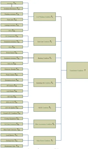
IV. SELECT CONDITION EVALUATION FACTORS By adopting fuzzy comprehensive evaluation, the subjective arbitration in fault evaluation can be overcome. Each factor affecting the fault can be comprehensively demonstrated to make the evaluation result more rational. In order to obtain comprehensive evaluation factors and authentically reflect the operating condition of a transformer, upon considerations of the feasibility of transformer condition evaluation, condition parameters are selected from each transformer component, including coil winding, iron core, bushing, OLTC, insulating oil, other accessories, and other factors. The evaluation system architecture of transformer conditions is shown in Fig. 1.
Transformer Condition T
OLTC Condition T5 Iron Core Condition T2
Bushing Condition T3
Insulating Oil Condition T4
Cooling Equipment T61
Coil Winding Condition T1
Other Factor Condition T7 DGA of LTC T51
LTC Oil Quality T52
Overall LTC Condition T53
Load History T71
Furfural Test T72
Maintenance Data T73 Power Factor T11 Insulation Resistance T12
Winding resistance T13
Turns ratio T14
Leakage reactance T15
Power Factor T31
Insulation resistance T32
Infra red T33 DGA T16
Other Accessories Condition T6 Oil Tank Corrosion T62
Main Tank Corrosion T63 IFT dyn/cm T44 Dielectric Strength T41
Water Content T42
Dissipation factor T43
Acid Numer T45
OIl Color T46 Oil Temperature T21
Insulation resistance T22
DGA T23
Fig.1 transformer conditions V. ESTABLISH A COMMENTS SET
After the evaluation factors of a transformer are determined, transformer conditions are classified in order to establish the comments set of each factor for fuzzy comprehensive evaluation. The transformer conditions are classified as good, acceptable, need caution, and poor in this paper, which are expressed as V={good, acceptable, need caution, poor}={v1,
v2,v3,v4}. A good condition means that the test data of transformer operations are normal, and each quantity of condition deviates significantly from the regulated attention value. Fault occurrence probability is low and long term operation is available. An acceptable condition means that the transformer has been operated for a certain time, and the test data are normal or the reliability of certain individual quantity of a condition is slightly reduced. As the data are reliable, its operation can be continued and fault probability is low. A need caution condition means that during the test period, the test data deviate from the normal condition. Some quantities of
the maintenance period should be shortened. A poor condition means that the overall operation properties of the transformer are below average. Most of the quantities of conditions obtained by testing and detection exceed the standards, and the probability of fault occurrence is high. A normal condition can be recovered through maintenance. Maintenance with power cuts can be considered to meet the demands of power system operations.
VI. DETERMINE THE SUBORDINATE FUNCTION OF EVALUATION FACTORS
A. Relative degradation degree
The concept of relative degradation is introduced to represent the relative degradation degree between the current transformer condition and the fault condition [8]. It is a quantified index with a value range of “0 to 1”. According to different values, degradation degrees of index conditions can be shown.
For a higher index values, indices such as the insulation resistance are better. The calculation of the index is as follows (1).
(1) For a lower index value, indices such as the dielectric dissipation are better. The calculation of the index is as follows (2).
(2) In the equation: Ii denotes the relative degradation of the i condition index; Xo denotes the allowable value of this index (value of good condition); Xmax or Xmin denotes the limit value of the index; Xi denotes the actual measured value; k denotes the degree of effect of parameter change on equipment condition, and is determined with the value of 1 in this paper.
B. Determine the subordinate function of test index
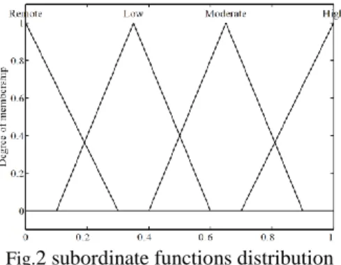
There are many methods for determining the subordinate function; however, there is no uniform pattern. The common method is the fuzzy distribution method. According to the characteristics of the problems, the existing fuzzy distribution of a certain pattern, and the measured data, the parameters in the distribution can be determined. The subordinate functions can have different shapes, such as triangle or ladder-shaped. As the subordinate function of a triangle has a simple shape and is easy to calculate, and the obtained result has little difference compared to that of other complex subordinate functions, it is widely adopted. This study adopted the triangle distribution function to determine the subordination degree. The subordinate function of each evaluation factor is established according to the standards of the hierarchical system. The subordinate functions distribution is shown in Fig. 2.
Fig.2 subordinate functions distribution
To determine the subordinate functions of the evaluation factors, the parameters are converted into functions within a range from “0 to 1”. The triangle distribution function is then used to determine the subordination degree. Therefore, the concept of relative degradation is introduced. By calculating the relative degradation degree of evaluation factors, parameters are converted into the functions within a range from
“0 to 1”. Finally, the subordination degree of the relative degradation of the four operating conditions in the comments set is calculated. The representation of the relationship between the relative degradation and the transformer operating condition can serve as reference to the semantic definition of the relative degradation degree, as shown in Table I .
TABLEI
SEMANTIC DEFINITION OF RELATIVE DEGRADATION
Numeric area of
degradation Semantic description of transformer condition 0~0.25 The equipment is in good condition and can continue to
operate.
0.25~0.5 A low degradation. The equipment is in normal operating condition.
0.5~0.75 A medium degradation. Slight faults occur, observation and detection should be enhanced.
0.75~1.0 The condition has shifted from the degradation condition to the fault condition. Serious faults have occurred.
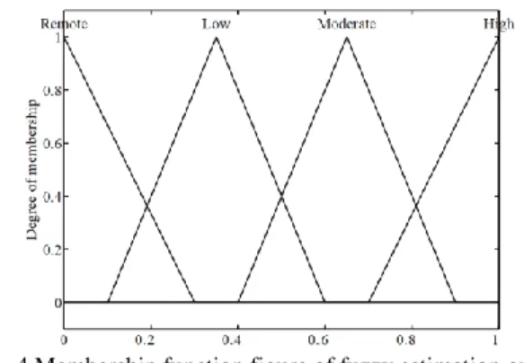
C. Setting subordinate functions of electric test indices By relative degradation, the data of electric testing are converted into a numerical value within the range of “0 to 1”, which can represent each input parameter. The input parameters of failure occurrence are described as Good, Acceptable, Need Caution, and Poor. The input values of parameters, fuzzy language definitions, and membership functions are as shown in Table II 、Table III、 Table IV and Fig.
3. Subordinate functions of all evaluation factors can be obtained, which will not be detailed here. The output numerical value of each fuzzy estimation, fuzzy language definition, and membership function are as shown in Table V. The present membership function is roughly set and will be revised and adjusted according to future practices and experiences to make the membership function more perfect and objective. [Max-min synthesis] of Mamdani fuzzy model is adopted in this paper for fuzzy estimation [9]–[11].
![圖 14 可控整流充電機 Matlab/simulink 整體架構 六、 範例模擬系統之建立 本文參照台灣電力公司再生能源發電系統併聯要點[15],設計一包含柴油引擎發電機、風力發電機 及太陽能發電模組等 DG 之微電網範例系統,其系統單線圖及參數分別如 圖 15 與 表 3 所示。並應 用 Matlab/Simulink 建構此微電網範例系統,如 圖 15 所示,本計畫未來將利用此範例系統,模擬與 分析此系統分別運轉於(1)併網運轉模式(2)孤島運轉模式時之保護協調。 B](https://thumb-ap.123doks.com/thumbv2/9libinfo/9127850.411990/12.892.205.699.55.403/可控整流充電整體架構系統之系統併計一包含柴系統其系統單系統如.webp)