Electrically controllable and polarization-independent Fresnel zone plate in a circularly symmetric hybrid-aligned liquid crystal film with a photoconductive polymer layer
K.-C. Lo, J.-D. Wang, and C.-R. Lee
a兲Institute of Electro-Optical Science and Engineering, National Cheng Kung University, Tainan, Taiwan 701, Republic of China
T.-S. Mo
Department of Electronic Engineering, Kun Shan University of Technology, Tainan, Taiwan 710, Republic of China
共Received 30 July 2007; accepted 5 October 2007; published online 30 October 2007兲
This work reports a Fresnel zone plate in a circularly symmetric hybrid-aligned liquid crystal 共LC兲 film with a photoconductive polymer layer. An ultraviolet-induced electrodelike pattern of polymer layer under a zone plate photomask results in alternating major and minor portions of external voltage dropping on LC layer in conductive and nonconductive regions, respectively. These effects cause the discrepancy in LC reorientation between adjacent zones, generating a Fresnel zone plate.
The focusing of the zone plate is electrically controllable and polarization independent.
Additionally, the zone plate has advantages of a zero focusing in the voltage-off state and a very small operating dc field range from 0 to 0.3 V / m. © 2007 American Institute of Physics.
关DOI: 10.1063/1.2802568兴
In recent years, numerous Fresnel zone plates have been developed for various fields, including optical communica- tion, photonics, space navigation, and optical imaging.
1–5Conventional Fresnel zone plates, fabricated by electron- beam writing or thin film deposition, have certain limita- tions, including static focusing. Controllable Fresnel zone plates with programmable focusing, based on flexibly con- trollable liquid crystal 共LC兲 materials, have been, accord- ingly, comprehensively studied.
6–11The effective phase difference between the incident light through the adjacent odd and even zones in a binary-phase LC Fresnel zone plate is electrically tunable. Diffraction may be maximized by set- ting the effective phase difference equal to an odd multiple of ; no diffraction occurs when this difference is an even multiple of . Therefore, Fresnel zone plates can be adopted as diffractive focusing elements.
12The polarization independence of the programmable focusing feature of a LC Fresnel zone plate is very im- portant. Two approaches have been employed to fabricate polarization-independent LC Fresnel zone plate. They are photolithographic
9and photoalignment techniques.
10,11Re- gardless of the method used, the LC structures are formed to be mutually orthogonal in neighboring zones of the zone plate, resulting in a nonzero but nonmaximal diffraction ef- ficiency in the voltage-off state. This inherent ability in these zone plates results in an inevitable detrimental higher power consumption.
10,11Hence, this work presents a peculiar ap- proach for generating a circularly symmetric hybrid-aligned LC Fresnel zone plate with an UV-induced electrodelike pat- tern of the polymer layer. The low and high conductivities, resulting in minor and major portions of external voltage dropping on the LC layer in the nonconductive and conduc- tive regions, respectively, cause a difference between LC re- orientations in the adjacent zones, thus forming the LC
Fresnel zone plate. The programmable focusing feature of the formed zone plate is polarization independent and elec- trically controllable. Additionally, the LC Fresnel zone plate has the advantage of a very low operating dc voltage range 共0–2.4 V兲 in a cell with a thickness of 8 m and a moderate diffraction efficiency 共18%兲.
Figure 1 schematically presents the procedure for fabri- cating the Fresnel zone plate in a circularly symmetric hybrid-aligned LC cell with a photoconductive polymer layer. The zone plate photomask has a key role in this work;
it has transparent odd zones and opaque even zones, as shown in Fig. 1共a兲. The used photomask with 80 concentric rings within a diameter of 1 cm was formed by etching a chromium oxide layer using electron-beam lithography. The related information about the photomask used herein can be found in Ref. 13.
In Fig. 1共a兲, a nonpolarized UV light 共from a 7.5 W Hg lamp兲 with an intensity of 9.2 mW/cm
2selectively illumi- nates a photoconductive polymer film 关poly共N-vinyl carba- zole兲 共PVK兲兴 that is precoated over an indium-tin-oxide 共ITO兲 glass substrate using a zone plate photomask. The photomask is in contact with the PVK film during irradiation
a兲Author to whom correspondence should be addressed. Electronic mail:
FIG. 1. Schematic diagram of fabrication procedure of LC Fresnel zone plate in a circularly symmetric hybrid-aligned LC cell with a photoconduc- tive polymer layer. Two substrates with a PVA-PVK-ITO film and a DMOAP-ITO film are combined to produce an empty cell. The PVA film is rubbed in the direction of eˆon xy plane.
APPLIED PHYSICS LETTERS 91, 181104共2007兲
0003-6951/2007/91共18兲/181104/3/$23.00 91, 181104-1 © 2007 American Institute of Physics
Downloaded 12 Nov 2008 to 140.116.208.52. Redistribution subject to AIP license or copyright; see http://apl.aip.org/apl/copyright.jsp
with UV light. The thickness of the PVK film is measured to be ⬃0.25 m. In 6 h, permanently conductive odd and non- conductive even regions are formed in the PVK layer, corre- sponding to the transparent odd zones and opaque even zones of the zone plate, respectively. The PVK electrode- like pattern with concentric rings is then generated over the ITO glass substrate. A poly共vinyl alcohol兲 共PVA兲 film with a thin thickness of ⬃50 nm is then coated over the PVK-ITO substrate and rubbed in the circular direction 共represented by the azimuthal unit vector 共eˆ
兲 on xy plane兲, as plotted in Fig. 1共b兲. At the same time, another ITO substrate is coated with a homeotropically aligned film of N , N-dimethyl-N-octadecyl-3-aminopropyltrimethoxysilyl chloride 共DMOAP兲. Such substrates with a PVA-PVK-ITO film and a DMOAP-ITO film are combined to produce an empty cell.
Then, the LCs 共E7, Merck, n
o= 1.5216, n
e= 1.7462兲 are injected into the empty cell and oriented themselves as a circularly symmetric hybrid structure, forming a LC Fresnel zone plate, as displayed in Fig. 1共b兲. The thickness of the plastic spacer of the cell is 8 m. As presented in Fig. 4 共a兲 , the LC molecules in the formed Fresnel zone plate are veri- fied to be aligned closely in the eˆ
direction by observation under a POM with crossed polarizers in both the odd and the even zones. The transmission axis of the polarizer 共analyzer兲 is set along x 共y兲 axis.
Figure 2 presents the experimental setup for examining the programmable focusing features of the formed LC Fresnel zone plate. The incident randomly polarized He–Ne laser beam 共=633 nm兲 is expanded and collimated via an expander with a magnifying power of 10 and then passes through a diaphragm 共D1兲 with a 1 cm diameter aperture and the LC Fresnel zone plate with an external applied dc voltage 共V兲. The polarization of the incident light is maintained lin- ear or random by passing or not passing the light through or not the polarizer 共P兲. A photodiode with a 1.1 cm active di- ameter, linked to a computer, is placed at a distance of
⬃40 cm from the LC Fresnel zone plate to measure the total transmission intensity and the first-order focusing diffracted intensity, in which another diaphragm D2 with a 1 mm di- ameter aperture is inserted in front of and close to the pho- todiode when the latter is measured.
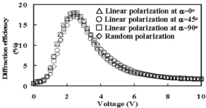
Figure 3 plots the variations in the first-order focusing diffraction efficiency with the applied dc voltage for the incident light with various linear polarizations, at ␣ = 0°
共triangle兲, 45° 共circle兲, and 90° 共square兲, and random polar- ization 共rhombus兲. The first-order focusing diffraction effi- ciency is defined as the ratio of the first-order diffraction
intensity to the total transmission intensity through the LC Fresnel zone plate. Figure 3 indicates that the electrically controllable first-order focusing diffraction efficiency from the LC Fresnel zone plate is entirely independent of the di- rection of the polarization of the incident beam including random polarization. This result is certainly reasonable be- cause the LC structures in the zone plate are always circu- larly symmetric at any applied dc voltage.
Notably, Fig. 1 共b兲 indicates that the LC structures in the even and the odd zones are equal in the voltage-off state, and no focusing effect is evident. This feature is independent of the cell thickness and the birefringence 共⌬n兲 of LCs and differs from that in all developed polarization-independent LC Fresnel zone plates.
9–11Its advantage is that it reduces the range of operating voltage in a certain cell thickness.
As presented in Fig. 3, as the applied dc voltage increases from 0 to 2.4 V, the first-order focusing diffraction effi- ciency from the LC Fresnel zone plate increases; it declines as the voltage increases over 2.4 V. When an external dc voltage is applied to the LC cell with PVK layers, the volt- age on the LC layer 共V
LC兲 in the steady-state regime can be written as
14V
LC= V
1 + 共d
PVK
LC兲/共d
LC
PVK兲 , 共1兲 where d
PVK共
PVK兲 and d
LC共
LC兲 are the thicknesses 共con- ductivities兲 of LC and PVK layers, respectively. Equation 共1兲 shows that the voltage dropping on the LC layer is dependent on the ratio of
LCto
PVK. If the PVK film is conductive 共
PVKⰇ
LC兲, the external voltage will drop mostly on the LC layer. If the PVK film is nonconductive 共
PVK⬍
LC兲, only minor fraction of external voltage will drop on the LC layer. In this work, when the external dc voltage is applied to the LC Fresnel zone plate, the conductivity in the con- ductive 共nonconductive兲 regions of the UV-induced PVK electrodelike pattern is high 共low兲, resulting in a major 共minor兲 fraction of external voltage dropping on the LC layer. These mechanisms may cause a discrepancy between LC reorientations and interference between the light rays that pass through each pair of adjacent odd and even zones, re- sulting in the programmable focusing effect. By comparing Fig. 4共a兲 共at V=0 V兲, Fig. 4共b兲 共at V=2.4 V兲, and Fig. 4共c兲
FIG. 2. Experimental setup for examining the focusing properties of the LC Fresnel zone plate. P polarizer; D1 and D2 diaphragms.
FIG. 3. Measurement of polarization-independent programmable focusing feature of the LC Fresnel zone plate: variation of first-order focusing dif- fraction efficiency through LC Fresnel zone plate under applied external dc voltage for incident light with various linear polarizations, at polarizing angles of 0°共triangle兲, 45° 共circle兲, and 90° 共square兲, and random polariza- tion共rhombus兲.
181104-2 Lo et al. Appl. Phys. Lett. 91, 181104共2007兲
Downloaded 12 Nov 2008 to 140.116.208.52. Redistribution subject to AIP license or copyright; see http://apl.aip.org/apl/copyright.jsp
共at V=10 V兲, it indicates that the LCs in the nonconductive regions cannot reorient in the range of operating voltages 共0–2.4 V兲, but can reorient as exceeding this range, because the voltage on the LC layer in these regions is small enough 共lower than the threshold voltage兲 at 0–2.4 V, but not at V ⬎2.4 V. However, in the conductive regions, a major por- tion of the external voltage drops on the LC layer such that the LCs can reorient at a small voltage 共larger than the threshold voltage兲 at 0–2.4 V.
In this experiment, the incident light field E
in, with a linear polarization at a polarizing angle of ␣ with respect to x axis in the xy-coordinate system, is given by
E
in= E
0冋 cos sin ␣ ␣ 册 . 共2兲
The circularly symmetric distribution of the LCs on the plane of the zone plate is such that the x ⬘ y ⬘ -coordinate system, which is a principal axis coordinate system, in Fig. 1共b兲 is established to make an included angle of with respect to xy-coordinate system, in which x ⬘ and y ⬘ axes are parallel and perpendicular to the short axis of the LC director, respec- tively. Through transforming E
ininto the x ⬘ y ⬘ -coordinate system by introducing the mutually orthogonal field compo- nents along x ⬘ and y ⬘ axes, the individual phase retardation via the LC layer and then transforms the outgoing field 共in the x ⬘ y ⬘ -coordinate system兲 back into the xy-coordinate sys- tem; the outgoing field E
outthrough the LC zone plate in the xy-coordinate system is given by
E
out= E
0冉 cos ␣ 冋 a b 册 + sin ␣ 冋 b a 册 冊 , 共3兲
where a and b represent the terms cos
2 exp共i2 dn
o/ 兲 + sin
2 exp共i2 dn
eff/兲 and cos sin exp共i2 dn
o/ 兲 + exp共i2 dn
eff/兲, respectively. n
o共n
eff兲 is the ordinary 共effective extraordinary兲 refractive index of LCs that is experienced by the component of the light field parallel 共perpendicular兲 to the short axis of the LC director. Since the conductivities are different in the even and odd zones at V⫽0, n
effvaries with voltage as given by n
eff共even兲共V兲 and n
eff共odd兲共V兲 in these two zones. Substituting the result of Eq. 共3兲 into the mth-order diffracted light field D
m, which can be determined by the mth Fourier component of the outgoing light field, yields
11D
m=
冕0 2A1E
oute
−i2m共A/2A1兲dA
2A
1= E
0共1 − e
−im兲
2 mi 冋 e
i共2dno/兲+ e
i共2dneff共odd兲/兲+ 共e
i共2dno/兲+ e
i共2dneff共even兲/兲兲
e
im册 冋 cos sin ␣ ␣ 册 , 共4兲
where r
1and A
1denote the radius and the area of the first odd zone of the zone plate, respectively. The diffraction ef- ficiency of the first-order 共m= ±1兲 diffracted beams is there- fore given by
±1⬅ 兩D
±1兩
2兩E
in兩
2= 1
2冋 1 − cos冉2 d⌬n
eff冊册 , 共5兲
where ⌬n
effequals n
eff共even兲− n
eff共odd兲. From Eq. 共5兲, the first- order efficiency of diffraction from the zone plate is indepen- dent of the direction of polarization of the incident beam, confirming the results that are plotted in Fig. 3. The even orders of the diffraction light all vanish according to Eq. 共4兲.
When the phase difference, 2 d⌬n
eff/ , in Eq. 共5兲 equals , the maximum first-order diffraction efficiency of ⬃20%, which approaches the experimental value of ⬃18%, can be obtained.
In summary, this work elucidates a Fresnel zone plate based on a circularly symmetric hybrid-aligned LC film with a photoconductive polymer layer. Experimental results reveal that the focusing feature of the LC Fresnel zone plate is polarization independent and electrically controllable. Addi- tionally, the LC zone plate provides advantages of a zero focusing in the voltage-off state, a low operating dc field range from 0 to 0.3 V / m, and a moderate diffraction effi- ciency 共⬃18%兲.
The authors would like to thank the National Science Council of the Republic of China, Taiwan, for financially supporting this research under Contract No. NSC 95-2112- M-006-020-MY2.
1M. Makowski, G. Mikula, M. Sypek, A. Kolodziejczyk, and C.
Prokopowicz, Proc. SPIE 5484, 475共2004兲.
2E. Marom, E. Ben-Eliezer, L. P. Yaroslavsky, and Z. Zalevsky, Proc. SPIE 5227, 8共2004兲.
3X. Ren, S. Liu, and X. Zhang, Proc. SPIE 5456, 391共2004兲.
4S. C. Kim, S. E. Lee, and E. S. Kim, Proc. SPIE 5443, 250共2004兲.
5J. T. Early and R. Hyde, Proc. SPIE 5166, 148共2004兲.
6H. Ren, Y.-H. Fan, and S.-T. Wu, Appl. Phys. Lett. 83, 1515共2003兲.
7Y.-H. Fan, H. Ren, and S.-T. Wu, Opt. Express 13, 4141共2005兲.
8T.-H. Lin, Y. Huang, A. Y.-G. Fuh, and S.-T. Wu, Opt. Express 14, 2359 共2006兲.
9G. Williams, N. J. Powell, A. Purvis, and M. G. Clark, Proc. SPIE 1168, 352共1989兲.
10D.-W. Kim, C.-J. Yu, H.-R. Kim, S.-J. Kim, and S.-D. Lee, Appl. Phys.
Lett. 88, 203505共2006兲.
11L.-C. Lin, H.-C. Jau, T.-H. Lin, and A. Y.-G. Fuh, Opt. Express 15, 2900 共2007兲.
12E. Hecht, Optics, 4th ed. 共Addison Wesley, San Francisco, 2002兲, Chap. 10, p. 495.
13K. Rastani, A. Marrakchi, S. F. Habiby, W. M. Hubbard, H. Gilchrist, and R. E. Nahory, Appl. Opt. 30, 1347共1991兲.
14F. L. Vladimirov, A. N. Chaika, I. E. Morichev, N. I. Pletneva, A. F.
Naumov, and M. Yu. Loktev, J. Opt. Technol. 67, 712共2000兲.
FIG. 4. Central part of observed images of LC Fresnel zone plate under a POM with crossed polarizers at共a兲 0, 共b兲 2.4, and 共c兲 10 V. The transmis- sion axis of the polarizer is parallel to the x axis.
181104-3 Lo et al. Appl. Phys. Lett. 91, 181104共2007兲
Downloaded 12 Nov 2008 to 140.116.208.52. Redistribution subject to AIP license or copyright; see http://apl.aip.org/apl/copyright.jsp