國立臺灣大學電機資訊學院電機工程學系 碩士論文
Department of Electrical Engineering
College of Electrical Engineering and Computer Science National Taiwan University
Master Thesis
使用低成本雷射測距儀與即時組織硬度估測之 適應性軌跡規劃系統於機器人按摩之研究
Adaptive Trajectory Generation of Robotics Therapeutic Massage Using Low-Cost Laser Range Finder with
In-Situ Tissue Stiffness Estimation
唐莉彤 Li-Tung Tang
指導教授:羅仁權 博士 Advisor: Ren C. Luo, Ph.D.
中華民國 106 年 7 月
July 2017
誌謝
就讀碩士班這兩年是我人生裡一段美好的回憶。雖然一路走來不易,但還好 有大家的支持與陪伴我才能有今日的成就。感謝父母親的栽培教誨、支持鼓勵,
讓我能夠全心全意奮力一搏,專注於我喜愛的領域。 特別感謝指導教授羅仁權老 師讓我有學習的機會。老師經常陪著我們熬夜,給我們指點迷津,每一次的實驗 瓶頸,每一個文法的迷惘,都謝謝有老師及時的援手。當我感到疲憊,沒有堅持 下去的動力時,只要想到老師的拼勁,就讓我打包心情,重新面對挑戰。 感謝老 師提供我們豐富的資源及在研究過程中的教導。在兩年的碩士生涯中,從老師身 上學到許多,老師充分地展現出國際級專家學者的風範與視野,不僅帶領我們探 索學術知識上的深度與廣度,在待人處事方面,老師更是教給我們許多社會上應 對進退的準則,期望我們成為均衡發展的人才,這一切都使我獲益良多。感謝康 仕仲老師以及鄒杰烔老師百忙之中擔任我的口試委員,並給予我的論文諸多的建 議及指教。回想兩年前,剛決定從光電領域跨到電機時,心中既期待又對未知的 未來感到些許徬徨。一開始對程式不太熟悉的我,經過兩年在實驗室的學習,成 長進步很多。在實驗室不僅培養軟體相關能力,也有許多機會接觸硬體,擁有軟 硬體整合的能力,是相當難得的體驗也是此實驗室給我最大的禮物。謝謝我同窗 兩年的同學,感謝你們在我人生迷惘、情緒低落時,給我鼓勵,帶給我無限的希 望,也對於我的研究提供了許多好的建議與想法。俊豪、晴岡、柏凱、李晟、靖 霖、達方,謝謝你們在一起修課時幫我解答問題。謝謝當時一起比賽的長鈞、孟 勳、仲凱,謝謝你們給我一個這麼棒的經驗,也讓我更加確信團隊合作的重要,
創造了寶貴的回憶。謝謝按摩機器人組的凱鈞、昱佑,謝謝你們總是在研究上給 予我幫助,一起做實驗一起討論,給予我許多技術上的教學以及在面臨低潮時鼓 勵我,成為我最佳的夥伴。同時我也感謝實驗室學弟妹,總是義不容辭的協助我 做實驗,幫忙舉辦實驗室的活動。也感謝實驗室的學長,在研究上有相關問題,
總是熱心回答並提供許多寶貴的建議與經驗,解決我在研究路上有遇到的瓶頸。
能完成這篇論文,我要感謝生命中的每一個人,真的非常謝謝你們。
唐莉彤 謹誌
中文摘要
隨著人口老化與人們對生活品質的要求提升,服務與醫療照護型機器人逐漸 走入我們的生活中,具有相當大的市場。現代人壓力大作息不正常,常常造成肩 背痠痛,而按摩為一種常見的舒緩方式,其不只幫助人們放鬆也可被視為是一種 治療。若機器人可被應用於按摩上,不僅能解決醫療人力不足的問題也可增進醫 療品質。
本篇論文以雙手臂機器人於肩背按摩為主軸,發展出一套完整的自動化按摩 流程。該流程包含使用自製的低成本雷射測距儀產生專屬個人的適應性按摩軌跡,
以及加入即時組織估測系統使機器人在按摩過程中能自行估測被按摩部位組織的 厚度與硬度。按摩前置部分。在以往,機器人的按摩軌跡大多透過教導的方式或 是利用使用者介面來產生,此作法耗時又耗費人力。而在此我們使用自製低成本 的 3D 雷射測距儀搭配現有的變形演算法找出人體肩部與背部的按摩軌跡。該雷射 測距儀具有與市售產品相當的精度且售價只需一般產品十分之一不到的價格。我 們利用此雷射測距儀掃描人體以產生背部的立體模型,並將該模型與預先建立已 具有標準按摩軌跡的模型做映射來找出專屬於每個人的按摩軌跡。實驗結果顯示 此方法所找出的按摩指壓點與專業按摩師所認可的指壓點平均距離誤差為 1 公分,
產生軌跡的的時間也只需教導方式的一半。在按摩的過程中,則加入了即時組織 估測系統。我們透過 7 軸手臂等速按壓人體背部找出皮膚組織力量與深度的曲線,
將人體的皮膚特性模組化為一正切函數。實驗中機器人雙手前端裝有力/力矩感測 器,可即時量測按摩器具與被按摩者間所受的力。我們將此力與機器人末端的移 動做為估測演算法中訊號的輸出與輸入,並藉由遞迴最小平方法加上遺忘因子在 按摩中即時找出函數當中的參數以估測組織的軟硬。該實驗分為模擬與實際量測。
模擬結果顯示該演算法可在 20 秒內估測出組織的特性。而在實際量測中,機器人 對不同體型的受測者進行按壓按摩並估測骨頭周遭、硬肌肉、軟肌肉的組織的特 性。實驗結果顯示其可在 1 分鐘內估測出組織的特性且其結果與先前模組化的軟 組織模型趨勢相同並有潛力可做為判斷被按摩者身體狀況的標準。
關鍵字: 雙手臂機器人、低成本雷射測距儀、適應性按摩軌跡規劃、即時組織 硬度估測
ABSTRACT
With the increasing rate of the elderly and the promotion of life quality, service robot and health care robot play important roles in our life and have huge market potential. Modern people usually suffer shoulder and back pain because of the pressure and irregular routine. Massage, a common way to alleviate the pain, can help people relax as a therapy. If robots are able to be supplied for massage, it can solve the shortage of medical human and promote the quality of therapy. In this thesis, we develop a complete automated procedure on dual arm robot for shoulder and back massage application. It contains using self-developed low-cost laser range finder (LRF) to generate adaptive massage trajectory which is individual person specific and implementing in-situ tissue stiffness estimation to make robot can figure out the characteristics of patient’s soft tissue during massage. In pre-massage procedure, prior researches often apply teach and play or user interface to generating massage trajectory and these techniques are time-consuming and laborious. Here we use a 3D low-cost LRF made by ourselves and existing morphing algorithm to find the trajectory of shoulder and back massage. This LRF has the comparable performance as commercial products and its cost is less than 10% of the cost of general products. We use the LRF to scan human’s back and generate a 3D model. Then the standard model which has the massage trajectory we decide in advance will be mapped on the model of human’s back to generate the massage trajectory for different people with different size. The experimental results demonstrate that the average distance error between the acupressure points indicated by our method and the acupressure points defined by the massage therapist is 1cm and our method can save more than half the time needed with
use a 7 DoF arm to find the indentation-force curve of soft tissue and model the characteristics of soft tissue as a tangent function. The wrists of the robot are equipped with force/torque sensors which can detect the force between massage tools and the patient. We take this force and the movement of robot manipulator as output and input signals and apply the recursive modified least-squares algorithm with forgetting factor to find the parameters of the function and estimate the hardness and thickness of tissue.
From simulation results, the algorithm can estimate the characteristics of soft tissue in 20s. In the experiment, the robot executes pressing massage on different subjects with different body size and finds the characteristics of three types of soft tissues, which are the tissue that covers bony area, hard muscle, and soft muscle. From experimental results, it can estimate the characteristics of soft tissue in 1 minute. The estimation results have the same trend as the model of soft tissue we build previously and have the potential to be the judging criteria of body condition.
Keywords: dual arm robot, low-cost laser range finder, adaptive massage
trajectory generation, in-situ tissue stiffness estimation
TABLE OF CONTENTS
誌謝 ... I 中文摘要 ... II ABSTRACT ... III TABLEOFCONTENTS ...V LISTOFFIGURES ... VII LISTOFTABLES ... IX
CHAPTER 1 INTRODUCTION ... 1
1.1 MOTIVATION ... 1
1.2 RELATED WORK ... 4
1.2.1 Massage Trajectory Planning ... 4
1.2.2 Laser Range Finder ... 6
1.2.3 Interaction with Soft Tissue ... 7
1.3 OBJECTIVE ... 8
1.4 THESIS ORGANIZATION ... 9
CHAPTER 2 SYSTEM OVERVIEW ... 11
2.1 ANTHROPOMORPHIC DUAL ARM ROBOT ... 11
2.2 HARDWARE SYSTEM OF ROBOT ARM ... 12
2.3 KINEMATICS OF ROBOT ARM... 16
2.4 SYSTEM ARCHITECTURE ... 17
2.5 SOFTWARE ARCHITECTURE ... 20
CHAPTER 3 CONTROL TECHNIQUES ... 22
3.1 CARTESIAN IMPEDANCE CONTROL ... 22
3.2 JOINT IMPEDANCE CONTROL ... 24
3.3 ONLINE TRAJECTORY GENERATOR ... 24
3.4 GRAVITY COMPENSATION ... 27
3.5 MASSAGE TECHNIQUES ... 28
3.5.1 Pressing ... 28
3.5.2 Rubbing ... 28
3.5.3 Stroking ... 29
CHAPTER 4 LOW-COST LASER RANGE FINDER ... 30
4.1 SYSTEM DESCRIPTION ... 30
4.2 LASER BASED LINE SCANNER MODULE ... 34
4.3 PERFORMANCE AND COMPARISONS ... 39
CHAPTER 5 ADAPTIVE TRAJECTORY GENERATION ... 43
5.2 MORPHING ALGORITHM ... 45
5.3 HUMAN BACK FEATURE EXTRACTION ... 49
5.4 ADAPTIVE TRAJECTORY GENERATION ... 50
5.5 EXPERIMENTAL RESULTS ... 51
CHAPTER 6 IN-SITU TISSUE STIFFNESS ESTIMATION ... 58
6.1 MODELING OF SOFT TISSUE ... 58
6.1.1 Experiment Setup ... 59
6.1.2 Model of Soft Tissue ... 60
6.2 IN-SITU TISSUE STIFFNESS ESTIMATION ... 63
6.2.1 Basic Adaptive Law ... 64
6.2.2 In-Situ Tissue Stiffness Estimation ... 65
6.3 SIMULATION AND EXPERIMENT ... 67
6.3.1 Simulation ... 68
6.3.2 Experiment ... 70
CHAPTER 7 CONCLUSIONS AND FUTURE WORK ... 77
7.1 CONCLUSIONS ... 77
7.2 FUTURE WORK ... 79
REFERENCES ... 81
VITA ... 87
LIST OF FIGURES
FIG.1-1 THE DUAL ARM ROBOT FOR MASSAGE APPLICATION. ... 1
FIG.1-2 THE MASSAGE FUNCTIONS OF THE DUAL ARM ROBOT. ... 2
FIG.1-3 THE COMMERCIAL LRF PRODUCTS.LEFT:SICKRIGHT:HOKUYO ... 3
FIG.1-4 THE LASER DISTANCE SENSORS DEVELOPED FROM RELATED WORK.LEFT:LRF BASED ON TRIANGULATION.RIGHT:TINY LRF BASED ON TIME-OF-FLIGHT (TOF). ... 6
FIG.2-1 THE ANTHROPOMORPHIC DUAL ARM ROBOT DEVELOPED IN NTU-ICEIRALAB. ... 11
FIG.2-2 THE ANTHROPOMORPHIC DUAL ARM ROBOT WHICH WE ARE DEVELOPING... 12
FIG.2-3 THE MECHANIC DESIGN OF THE ROBOT ARM. ... 13
FIG.2-4 THE MOTOR AND THE DRIVER USED IN EACH JOINT. ... 14
FIG.2-5 THE MECHANISM OF HARMONIC DRIVE. ... 15
FIG.2-6 THE 6-AXIS F/T SENSOR IS MOUNTED ON THE WRIST OF EACH ROBOT ARM. ... 15
FIG.2-7 LINK COORDINATE SYSTEMS OF THE 6-DOF ROBOT ARM. ... 16
FIG.2-8 THE SYSTEM ARCHITECTURE OF THE DUAL ARM ROBOT. ... 19
FIG.2-9 RTX REAL-TIME PLATFORM. ... 19
FIG.2-10 THE SOFTWARE ARCHITECTURE OF THE DUAL ARM ROBOT. ... 21
FIG.3-1 THE MASS-SPRING-DAMPER SYSTEM. ... 22
FIG.3-2 THE SCHEMATIC DIAGRAM OF MANIPULATOR WITH EXTERNAL ENVIRONMENT. ... 23
FIG.3-3 THREE PHASES OF ONLINE TRAJECTORY GENERATOR. ... 25
FIG.3-4 THE CONTROL DIAGRAM OF CARTESIAN IMPEDANCE CONTROL. ... 26
FIG.4-1 THE STRUCTURE OF THE SELF-DEVELOPED LASER RANGE FINDER. ... 31
FIG.4-2 THE COMPONENTS OF THE SELF-DEVELOPED LASER RANGE FINDER. ... 31
FIG.4-3 THE BLOCK DIAGRAM OF THE ELECTRONIC COMPONENTS. ... 32
FIG.4-4 TRIANGULATION GEOMETRY OF SINGLE-POINT LASER SENSOR MODULE. ... 35
FIG.4-5 TRIANGULATION GEOMETRY OF LASER BASED LINE SCANNER MODULE. ... 36
FIG.4-6 THE SPATIAL RELATIONSHIP BETWEEN THE LASER DOT AND THE ROTATION CENTER. .... 38
FIG.4-7 HOKUYO URG-04LX LASER RANGE FINDER. ... 39
FIG.4-8 THE IMAGES CAPTURED FROM THE CAMERA AT DIFFERENCE DISTANCE.(A) 0.45M (B) 0.65M (C)0.9M ... 40
FIG.4-9 DISTANCE ERRORS FOR 90% REFLECTANCE... 40
FIG.4-10 WE TEST THE MODULE BY CONSTRUCTING THE 3D SURFACE OF A BOX.HERE PRESENTS THE RESULT IN FRONT VIEW AND TOP VIEW. ... 41
FIG.4-11 SCANNING RESULTS OF DIFFERENT OBJECTS. ... 42
FIG.5-1 THE FLOW CHART OF ADAPTIVE TRAJECTORY GENERATION. ... 43
FIG.5-2 LEFT:7 ACUPRESSURE POINTS ON BACK.RIGHT:WE MARK THEM BY COLOR LABELS. ... 44
FIG.5-4 THE PROCESSING OF MORPHING. FROM THE LEFT SIDE TO THE RIGHT ARE THE FIRST
IMAGE, MIDDLE IMAGE, AND SECOND IMAGE. ... 45
FIG.5-5 A PAIR OF LINES FOR FIELD MORPHING. ... 46
FIG.5-6 MULTIPLE LINE PAIRS FOR FIELD MORPHING... 47
FIG.5-7 THE MIDLINE OF HUMAN BODY. ... 49
FIG.5-8 (A)2D PROJECTION OF THE STANDARD 3D MODEL.(B)2D PROJECTION OF THE BACK OF SUBJECT #1.(C)THE RESULT OF MORPHING INDICATING THE ACUPRESSURE POINTS OF SUBJECT #1. ... 50
FIG.5-9 THE 3D MODEL OF THE SUBJECTS WITH DIFFERENT BODY SHAPE.THE GREEN DOTS ON THEIR BACKS INDICATE THE REAL ACUPRESSURE POINTS AND THE RED DOTS ARE THE MAPPED ACUPRESSURE POINTS FROM THE METHOD WE PROPOSE. ... 53
FIG.5-10 THE RUBBING TRAJECTORIES FOR DIFFERENT SUBJECTS. ... 54
FIG.5-11 THE STROKING TRAJECTORIES FOR DIFFERENT SUBJECTS. ... 54
FIG.5-12 THE TRAJECTORIES GENERATING FROM OUR PREVIOUS WORK. ... 55
FIG.5-13 APPLY SELF-DEVELOPED LRF TO UPPER BODY MASSAGE.LEFT:THE LRF IS MOUNTED IN FRONT OF THE DUAL ARM ROBOT.UPPER RIGHT:THE LRF IS SCANNING THE SUBJECT’S BACK.LOWER RIGHT:THE DUAL ARM ROBOT EXECUTES PRESSING ON SUBJECT’S BACK. ... 56
FIG.5-14 THE 3D MODEL OF THE SUBJECT LYING ON THE MASSAGE BED. ... 57
FIG.5-15 APPLY SELF-DEVELOPED LRF TO FULL BODY MASSAGE.LEFT: THE LRF IS MOUNTED WITH A TILT ANGLE IN FRONT OF THE MASSAGE BED. UPPER RIGHT: THE LRF IS SCANNING THE SUBJECT’S BACK. LOWER RIGHT: THE DUAL ARM ROBOT EXECUTES PRESSING ON SUBJECT’S BACK. ... 57
FIG.6-1 ANATOMY OF THE HUMAN SKIN. ... 58
FIG.6-2 EXPERIMENT SETUP OF MODELING OF SOFT TISSUE. ... 59
FIG.6-3 INDENTATION-FORCE GRAPH OF HUMAN BODY. ... 60
FIG.6-4 THE APPROXIMATE CURVE OF EACH TISSUE. ... 62
FIG.6-5 TWO PARAMETERS 𝛼 AND 𝛽 INDICATE THE CHARACTERISTIC OF THE SOFT TISSUE. ... 63
FIG.6-6 THE GRADIENT METHOD FOR ADAPTIVE LAW... 64
FIG.6-7 THE SIMULATION RESULTS OF EACH TISSUE. ... 70
FIG.6-8 EXPERIMENT SETUP.(A)THE DUAL ARM ROBOT EXECUTES PRESSING ON SUBJECT.(B) THE POINTS THAT INDICATE THE POSITIONS WE TEST... 70
FIG.6-9 THE EXPERIMENTAL RESULTS OF SUBJECT #1. ... 71
FIG.6-10 THE SIGNALS EXTRACT FROM SUBJECT #1. ... 72
FIG.6-11 THE SUBJECTS WITH DIFFERENCES.(A)SUBJECT #2(B)SUBJECT #3(C)SUBJECT #4 ... 74
FIG.6-12 THE ESTIMATION RESULTS OF 4 SUBJECTS WHO HAVE CONSIDERABLE SIZE DIFFERENCES. (A)SUBJECT #1(B)SUBJECT #2(C)SUBJECT #3(D)SUBJECT #4 ... 76
LIST OF TABLES
TABLE 2-1THE SPECIFICATIONS OF THE ROBOT ARM. ... 13
TABLE 2-2THE SPECIFICATIONS OF EACH JOINT. ... 14
TABLE 2-3D-H PARAMETERS OF THE 6-DOF ROBOT ARM. ... 17
TABLE 2-4THE SPECIFICATIONS OF IMP CARD. ... 18
TABLE 4-1THE PRICE AND THE PRODUCT TYPE OF THE COMPONENT. ... 32
TABLE 4-2EMISSION LIMITS FOR LASER SYSTEMS ... 33
TABLE 5-1FUNCTIONS OF EACH ACUPRESSURE POINT. ... 43
TABLE 5-2ERRORS OF TRAJECTORY GENERATION ... 53
TABLE 6-1PARAMETERS OF APPROXIMATE CURVES ... 61
TABLE 6-2ESTIMATION RESULTS OF 7 SUBJECTS ... 73
Chapter 1 Introduction
1.1 Motivation
Health care robots play important roles for humans with the rapid increase of the elderly population and an acute shortage of nurses. They have huge potential for improving quality of life by automating time-consuming and laborious medical procedures. There are different types of health care robots that have been proposed such as the nursing-care assistant robot RIBA [1], a mobility assistant robot [2], and the domestic health assistant robot MAX [3]. Massage is a non-invasive and effective therapy. It has lots of befits include pain relief, reduced trait anxiety and depression, and temporarily reduced blood pressure and heart rate. However, it is time-consuming and laborious. Therefore, robotics therapeutic massage is highly valued recently in the field of health care robots which can provide more diversified massage techniques, has wider workspace, and more closely meets the needs of users than a standard massage chair.
Fig. 1-1 The dual arm robot for massage application.
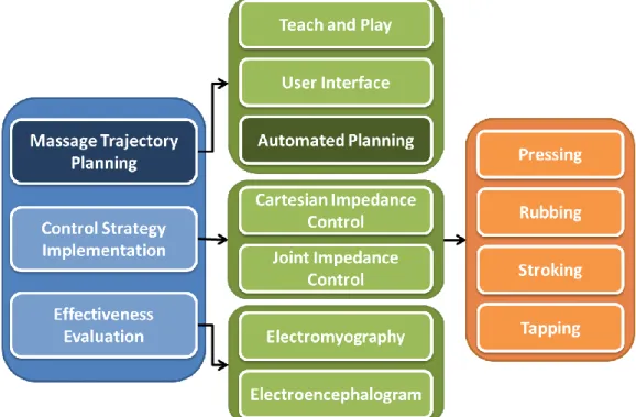
The dual arm robot for massage application is shown in Fig. 1-1. It is developed with three main topics (Fig. 1-2): massage trajectory planning, control strategy implementation, and effectiveness evaluation. Several studies have focused on the latter two parts. Huang et al. [4] [5] designed an anthropomorphic soft arm with integrated elastic joints and considered its contact dynamics for promoting quality of massage.
Ando et al. [6] evaluated the relaxation effect of the head massage robot with bio signals.
Our previous works have also discussed the impedance control of the multi-finger robot [7] and developed a robotics therapeutic massage evaluation system [8] [9] by using electromyography (EMG) and electroencephalogram (EEG) signals.
Fig. 1-2 The massage functions of the dual arm robot.
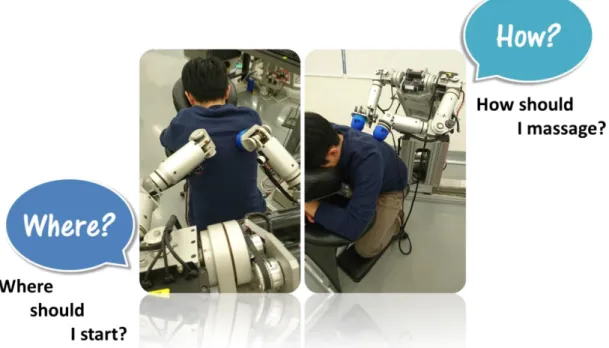
There have been papers discussing massage trajectory planning, but they often generate the trajectories through teach and play or user interface. They are not an automated process and unsuitable for different body shapes. It will cause a lot of inconvenience and it puts the cart before the horse. Like real masseur, the robot needs to
know “where” it should start to massage by itself. It should autonomously generate suitable massage trajectory for different people. To solve this problem, sensor is indispensable. However, sensor is another problem for robotics massage.
There are many sensors such as sonar, IR sensors, and Laser Range Finders (LRFs) can be used, whereas LRFs have the higher potential than other sensors due to their higher accuracy with fine angular and distance resolution and more dense distance measurements. The stumbling block to using LRF in general applications is the cost.
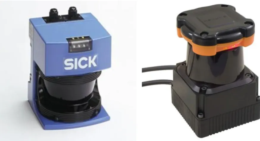
The main reasons of the high cost are the optical components and the scanning mirrors which are very fragile and expensive. Although many commercial products from famous company such as SICK and Hokuyo (Fig. 1-3) have been fully developed, the cost of them about several thousand US dollars still keeps them from common use.
Therefore, we have been finding a cheaper and more available way to make LRFs.
Fig. 1-3 The commercial LRF products. Left: SICK Right: Hokuyo
Although the robot can know where it needs to massage by sensors, it still needs to know “how” it should massage. For general masseur, they can know what kind of soft tissue they are massaging when they touch them and even can figure out the body condition of patients. Then they will use this information to determine the massage strategy such as massage duration and massage techniques. To provide patients more
comfortable and friendlier service, robot should have the same ability as real masseur.
Therefore, how to interact with soft tissue becomes important issue for robotics therapeutic massage. If we want the robot to achieve the goal, it needs to understand the characteristics of soft tissue and estimate the characteristics of patient’s soft tissue during massage. Other advantages of this ability are that the robot can adjust the control strategies according to tissue stiffness to make the control system more stable and it is able to evaluate the massage effectiveness by comparing the tissue stiffness before and after the massage.
Sum up the above perspectives, there are two problems to be solved. First one is make the robot autonomously generate adaptive massage trajectory by using not expensive sensor. Second one is let the robot can figure out the characteristics of patient’s soft tissue during massage.
1.2 Related Work
1.2.1 Massage Trajectory Planning
Teach and Play): Jones et al [10] developed a robotic system to provide basic
massage manipulations for medical therapy by employed a PUMA 562 robot. For trajectory generation, the trajectory is generated based on 4 data at the patient’s left and right shoulders and left and right points on the waist which are taught by masseur in Cartesian space. In order to obtain desired Cartesian trajectory, they use inverse kinematics and Jacobian matrix to get a desired sequence of joint positions and velocities. King et al [11] developed a system making the robot autonomously perform bed baths for patient hygiene. They acquired the spatial data of patients from a Hokuyo laser range finder and created a selection interface. The operator can use mouse to select
2 points and these 2 points will form the diagonal corners of a rectangular box which the operator wants robot to clean. They evaluate the performance of the system by making the robot remove a certain area of debris on human skin. The experimental results show that the robot can remove 96% of the debris on 4 parts of the limbs. Lu et al [12] designed a Chinese medical massage system which can record the acupressure points of patients by affixing color labels on back. Although the masseur can teach the robot the positon of acupressure points on human back, these points may be changed during massage and the robot will touch the wrong place. To avoid that happening, they affix the color labels on back as marks. When the robot executes massage, it can use camera to check the position of acupressure points at any time. Peng et al [13] also adopted similar method to record the acupressure points by recognizing the position of the masseur’s finger.
Automated Massage Trajectory Planning): Wei et al [14] presented a foot
massage robot which can reproduce the expert techniques of Chinese massage. For trajectory planning, they first measure the foot size to get patient’s pelma contours and find the coarse position of acupoints of pelmas by using a knowledge-based predictive model which is based on the feature points of foot. Then they adopt reinforcement learning optimization to correct the errors calculated through the prediction model and get the fine position of acupoints. Chen et al [15] developed a 2 DoF massaging robot prototype: Massagebot. It can realize massage by scratching and shaking on user’s back.
In order to get better efficacy, they proposed an algorithm which combine SOM (Self-organizing Feature Map) neural networks, image processing and pattern recognition to simplify acupuncture points and make the robot through the path which has most of acupressure points. The method we proposed previously [16] was based on
the human pose recognition methodology provided by [17]. We extracted point cloud data of human body shape from Kinect and estimated the frontal and sagittal planes by RANSC (RANdom Sample Consensus) algorithm to plan the massage trajectories for different shapes of a human body. Since it only depends on the planes of human body, the accuracy is not enough and the effectiveness cannot be proved.
1.2.2 Laser Range Finder
Konolige et al. [18] developed a laser distance sensor based on triangulation principle (Fig. 1-4(Left)). They adopted a point laser and low-cost CMOS imager as the emitter and the receiver to build an innovative laser point sensor module. Its cost is about $30 and it has the accurate range measurements at 6m with less than 3cm errors.
This approach can only get 2D information with one scan because of the point laser.
Chen et al. [19] proposed an ultra-tiny line laser range sensor based on the time-of-flight principle (Fig. 1-4(Right)). Its size is only 35mm×27mm×30mm which makes them possible for smaller robotics applications and the cost is $150 for prototype. The disadvantage of it is its measurable range is too short.
Fig. 1-4 The laser distance sensors developed from related work. Left: LRF based on triangulation. Right: Tiny LRF based on time-of-flight (TOF).
1.2.3 Interaction with Soft Tissue
Modeling of Soft Tissue): As far back as 1996, Chen et al [20] believe that
quantitative measurement of tissue elasticity is helpful to numerous potential clinical applications. They built a 1D ultrasound elasticity measurement system to investigate the elasticity of muscle and liver and compared the accuracy and consistency with mechanical measurements. They found that stress-strain curves of soft tissue have exponential shapes. Hu et al [21] also deduced the same characteristic of soft tissue.
They measured the mechanical properties of living tissue of person’s arm by a 4 DoF massage robot arm. There is a 6mm diameter tip mounted on the force sensor of robot arm. The tip obtains the external force on human tissue by moving at constant velocity to compress person’s arm. The experimental results have the same trend as [20].
Moreover, they found that different velocity will not affect the results. Yeh et al [22]
proposed a modified contact model that uses contact radius and contact force to estimate the elastic modulus of objects and proposed an image-assisted measuring system which adopts CCD camera to detect the contact radius and the contact force is extracted by tactile sensor. This method increases the accuracy of estimation. Yakovenko et al [23]
numerically figured out the model of the three-layer tissue, which simulates skin, muscle, and bone, and used the results to estimate the contact and internal stresses between the element of the medical robot and soft tissue. The algorithm they proposed reduces much time for signal and data processing while does not lead to loss of model adequacy.
Integration with Control System): Golovin et al [24] [25] consider that training
by demonstration in robotics is more natural for physician than training of force points using the manual by physician. The massage robot imitates the movement of masseurand recorded the force exerted on soft tissue by masseur through demonstration. In the free space, it only needs to care about the movement. But during massage, it should consider the interaction with soft tissue. In their model, they add the factor of the reaction force of soft tissue to make the robot can record the true force exerted by masseur and successfully reproduce the action of massage. Ott et al [26] [27] developed a hybrid system for impedance and admittance control. They found that impedance control is suitable for interactions with stiff tissue and admittance control is suitable for interactions with soft tissue, so they alternated the controller between these two control methods with different tissue stiffness which are known in advance. This research makes us understand the interaction between control and soft tissue better. Mouri et al [28] proposed an intelligent massage control system. They identified the characteristic of human skin muscle through robot perception of impedance control to determine the parameters of the controller. In the experiments, they estimated the suitable impedance control parameters for a soft tissue and a hard muscle. It successfully helped us handle the control strategy with soft and hard muscle.
1.3 Objective
In this thesis, there are two main issues to be solved. First one is make the robot can autonomously generate adaptive massage trajectory which is individual person specific by using a low-cost sensor. We aim to develop a low-cost laser range finder (LRF) which has lots of advantages than other sensors and we will focus on upper back massage which is the most common way in massage. Second one is to figure out the characteristics of soft tissue and let the robot can estimate the characteristics of patient’s soft tissue during massage. We will explore a more intuitive model than previous works and propose a method that can online estimate the characteristics of soft tissue.
Several sub-objectives of this thesis are presented as follow:
1. Develop a low-cost laser range finder which has the comparable performance with commercial products but the cost is less than 10% of the cost of them and make it can get 3D model with a single scan which is more convenient for massage trajectory planning.
2. Propose a method that can generate adaptive massage trajectory which is suitable for different people with different body size and individual person specific according to human back feature.
3. Apply the LRF and adaptive massage trajectory generation we propose to robotics therapeutic massage, including upper back massage and full body massage.
4. Explore the characteristics of soft tissue and propose a more intuitive model of soft tissue than previous work which can indicate the hardness and thickness of soft tissue.
5. Propose a method that can estimate the characteristics of patient’s soft tissue during massage by using the information from the reaction force by patient’s soft tissue and the movement of the robot manipulator.
1.4 Thesis Organization
The thesis is organized and described as follow: Chapter 1 discloses the motivation, related work, and the objective of this thesis. Chapter 2 gives a hardware and soft system description of the dual arm robot developed in our lab for robotics therapeutic massage. The control techniques of the dual arm robot, including different massage techniques are illustrated in Chapter 3. The hardware and software system and the laser module of the self-developed LRF are described in Chapter 4. The performance of the
LRF compared with commercial product is also presented in that chapter. Chapter 5 presents the methodology we propose in this thesis for adaptive massage trajectory generation which is based on morphing algorithm and medical knowledge, the experimental results are presented as well. Chapter 6 illustrates the intuitive model of soft tissue and describes the in-situ tissue stiffness estimation based on adaptive law for physical human-robot interaction; the experimental results of estimation are also presented. Finally, Chapter 7 concludes our works and discloses the future work in this thesis.
Chapter 2 System Overview
In this chapter, we disclose the hardware and software system of the dual arm robot developed in our lab for robotics therapeutic massage. We first give a system overview of the dual arm robot. Then we describe the hardware system and kinematics of the robot arm. Finally, the system structure and the software are presented.
2.1 Anthropomorphic Dual Arm Robot
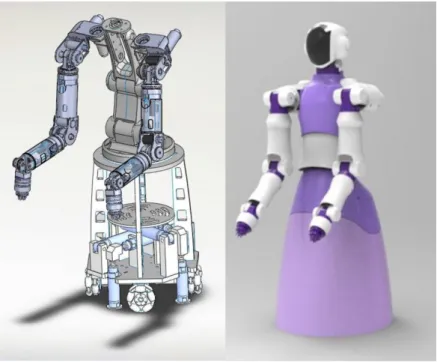
Fig. 2-1 shows the anthropomorphic dual arm robot system developed in NTU-iCeiRA Lab. It has 6 DoFs on each arm (3 rotational-DoFs in shoulder, 1 rotational-DoF in elbow, and 2 rotational-DoFs in wrist) and 1 DoF on the bottom with a linear motor for mobility. There are 13 DoFs in total.
Fig. 2-1 The anthropomorphic dual arm robot developed in NTU-iCeiRA Lab.
It is equipped with a sphere-shaped end-effector for performing a variety of massage techniques and a force/torque sensor on each wrist to measure the interactional force between the end effector and soft tissue of patient during massage. The torso is bended forward by 45 degrees to get a larger workspace in front of the robot. Its control
system is based on the real time operating system RTX on window PC.
We are also developing another anthropomorphic dual arm robot for health-care which is shown in Fig. 2-2. It has more DoFs which can performance more complex tasks not only massage. It has 7 DoFs on each arm, 3 DoFs on waist, 2 DoFs on head equipped with tablet for human-robot interaction, and 4 DoFs on the bottom which has 4 Omni-directional wheels for mobility. There are 23 DoFs in total. The end effector of the robot can be altered to accommodate different massage techniques to achieve the optimal effect.
Fig. 2-2 The anthropomorphic dual arm robot which we are developing.
2.2 Hardware System of Robot Arm
Fig. 2-3 shows the mechanic design of the robot arm. The length of each arm is about 60 cm. Its controllers are put in the torso. We take aluminum alloy as the material of the robot arm which can reduce its weight. Its specifications are presented in Table 2-1.
Fig. 2-3 The mechanic design of the robot arm.
Degree of Freedom (DoF) Length Weight
Shoulder: 3 DoFs
Shoulder: 115 mm Shoulder: 2.3 kg Upper arm: 300 mm Upper arm: 3.3 kg
Elbow: 1 DoF
Forearm: 300 mm Forearm: 2.2 kg Diameter: 100 mm Fist: 0.5 kg
Wrist: 2 DoFs Total length: 600 mm Total weight: 8.3 kg
Table 2-1 The specifications of the robot arm.
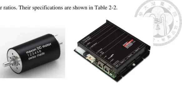
Each joint of the robot arm is actuated by a DC brush servo motor (Fig. 2-4(Left)) from Maxon. For massage application, we need a driver which can provide torque mode to make motor output desired torque and we also need a reduction gear which can reduce the rotational speed and transfer the energy to torque output to let motor has higher output torque. To satisfy our requirement, we take Maxon servo amplifier (Fig.
2-4(Right)) as the driver and adopt Harmonic Drive as the reduction gear. Compare to traditional reduction gear, Harmonic Drive has higher compactness, lighter weight and
higher gear ratios. Their specifications are shown in Table 2-2.
Fig. 2-4 The motor and the driver used in each joint.
Joint
Motor Type
Nominal Speed (rpm)
Nominal Torque (mNm)
Nominal Current
(A)
Torque Constant (mNm/A)
Harmonic Drive
Type
Gear Ratio
Shoulder
RE-50 5540 354 9.15 39.6 CSD-17-50 50
RE-50 5540 354 9.15 39.6 CSD-17-50 50
RE-40 6930 170 5.77 30.2 CSD-20-50 50
Elbow RE-40 6930 170 5.77 30.2 CSD-17-50 50
Wrist
RE-25 8360 26.7 1.17 23.4 CSD-14-100 100
RE-25 8360 26.7 1.17 23.4 CSD-14-100 100
Table 2-2 The specifications of each joint.
The mechanism of Harmonic Drive is shown in Fig. 2-5 [29]. It has 3 basic components: a wave generator (green), a flex spline (red), and a circular spline (blue).
Its theory is based on elastic dynamics and utilizes the flexibility of metal. It assumes that the wave generator is the input rotation. The key point of the mechanism is that the flex spline has fewer teeth than the circular spline has so that the flex spline is required to rotate a slight amount backward relative to the circular spline. Thus the rotation
action of the wave generator brings on a much slower rotation of the flex spline in the opposite direction.
The gearing reduction ratio can be calculated by the number of teeth on each gear as:
𝑟𝑒𝑑𝑢𝑐𝑡𝑖𝑜𝑛 𝑟𝑎𝑡𝑖𝑜 = 𝑓𝑙𝑒𝑥 𝑠𝑝𝑙𝑖𝑛𝑒 𝑡𝑒𝑒𝑡ℎ − 𝑐𝑖𝑟𝑐𝑢𝑙𝑎𝑟 𝑠𝑝𝑙𝑖𝑛𝑒 𝑡𝑒𝑒𝑡ℎ
𝑓𝑙𝑒𝑥 𝑠𝑝𝑙𝑖𝑛𝑒 𝑡𝑒𝑒𝑡ℎ (2.1)
Fig. 2-5 The mechanism of Harmonic Drive.
Fig. 2-6 The 6-axis F/T sensor is mounted on the wrist of each robot arm.
In order to measure the interactional force between the end effector and soft tissue of patient during massage for physical human-robot interaction and evaluating the quality of massage, the 6-axis force/torque sensor (HEX-70-CE-2000N) made by Optoforce is amounted on the wrist of each robot arm as shown in Fig. 2-6. This sensor
can measure 3 axis forces (x, y, z) and 3 axis torques (roll, pitch, yaw). Its diameter is 70mm and its height is 20mm. The maximum output force of the end-effector is about 140N.
2.3 Kinematics of Robot Arm
For any application of robot, we need to know the pose of the end-effector in Cartesian space and the angle of each joint in joint space which can be used to make the robot execute the behavior we want. Therefore, we use Denavit-Hartenberg (D-H) convention, which is a general principle to describe the relationship between every link coordinate system, to present the position and orientation of end-effector by a 4×4 homogeneous transformation matrix.
Fig. 2-7 Link coordinate systems of the 6-DOF robot arm.
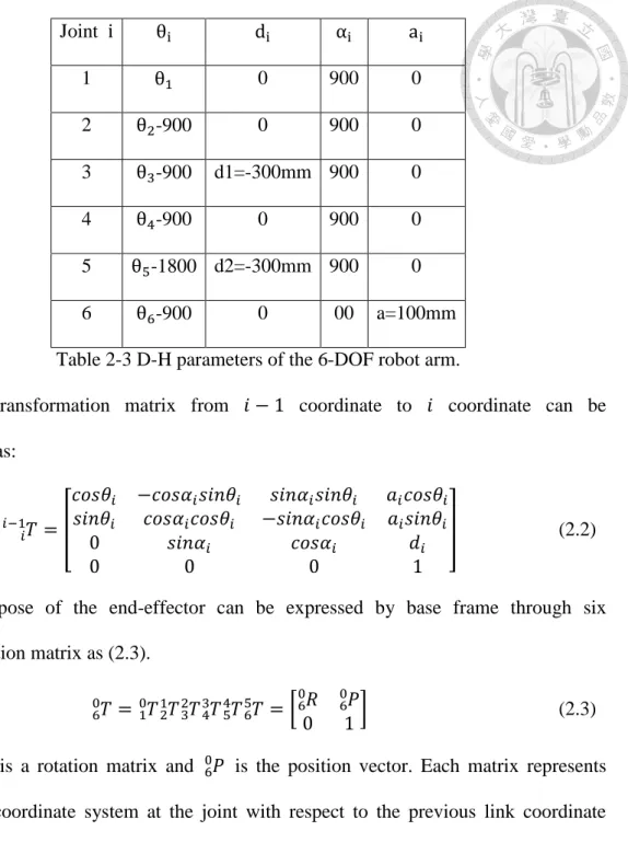
Fig. 2-7 shows the link coordinate systems of the robot arm and its D-H parameters are presented in Table 2-3. After we determine the reference frame and the D-H parameters, we can calculate the transformation matrix which presents the relationship between the pose (position and orientation) of the end-effector and the angle of each joint.
Joint i θi di αi ai
1 θ1 0 900 0
2 θ2-900 0 900 0
3 θ3-900 d1=-300mm 900 0
4 θ4-900 0 900 0
5 θ5-1800 d2=-300mm 900 0
6 θ6-900 0 00 a=100mm
Table 2-3 D-H parameters of the 6-DOF robot arm.
The transformation matrix from 𝑖 − 1 coordinate to 𝑖 coordinate can be calculated as:
𝑖𝑇
𝑖−1 = [
𝑐𝑜𝑠𝜃𝑖 −𝑐𝑜𝑠𝛼𝑖𝑠𝑖𝑛𝜃𝑖 𝑠𝑖𝑛𝛼𝑖𝑠𝑖𝑛𝜃𝑖 𝑎𝑖𝑐𝑜𝑠𝜃𝑖 𝑠𝑖𝑛𝜃𝑖 𝑐𝑜𝑠𝛼𝑖𝑐𝑜𝑠𝜃𝑖 −𝑠𝑖𝑛𝛼𝑖𝑐𝑜𝑠𝜃𝑖 𝑎𝑖𝑠𝑖𝑛𝜃𝑖
0 𝑠𝑖𝑛𝛼𝑖 𝑐𝑜𝑠𝛼𝑖 𝑑𝑖
0 0 0 1
] (2.2)
Then the pose of the end-effector can be expressed by base frame through six transformation matrix as (2.3).
6𝑇
0 = 𝑇10 21𝑇32𝑇43𝑇54𝑇65𝑇= [ 𝑅60 60𝑃
0 1] (2.3)
where 60𝑅 is a rotation matrix and 60𝑃 is the position vector. Each matrix represents each link coordinate system at the joint with respect to the previous link coordinate system.
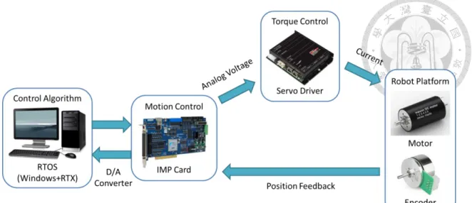
2.4 System Architecture
The system architecture of the dual arm robot is shown in Fig. 2-8. To give patient a good massage experience, the force acted on patient is considered as first priority instead of the accuracy of position. So we adopt the torque control rather than implement the position control. The control algorithms are coded in PC and the torque
output of the motors are monitored by servo drivers. The servo drivers will send corresponding current to motors to let the motors output desired torque. But these servo drivers only can accept analog voltage as input signals, there is the difficulty with communication between PC and servo drivers. Therefore, we adopt a motion control card to solve this problem. The motion control card we use is Intelligent Motion control Platform (IMP, ITRI) developed by Industrial Technology Research Institute. It main purposes are to convert the digital signals from PC to the analog voltage signals which can be compatible for servo drivers and convert the position information of encoders to the signals which can be interpretable by PC. The specifications of the IMP card are illustrated in Table 2-4.
CPU
400MHz 32bit 7-stage pipeline RISC 32KB D Cache / 32KB I Cache
FPU 100MHz 5-stage double precision FPU with 2.0 MFLOPS/MHz PCI-Bridge 33MHz 32bits 132MB/sec
DDR-Controller 100MHz DDR 128MB Ethernet-Controller 10/100Mbps
UART 115200bps
Pulse-Generator 8 sets of 25MHz, function of DDA
Encoder 8 sets of 32bit 4MHz differential input +digital filter
DAC 8 sets of 16bits -10V~10V
ADC 8 sets of 14bits 116ksps -5V~5V(Bipolar)0~10V(Unipolar) Table 2-4 The specifications of IMP card.
Fig. 2-8 The system architecture of the dual arm robot.
Microsoft Windows is the most widely used operating system in the world.
However, there is a crucial issue of this system for control. Because it is a multitasking operating system which has ability to run more than one thread in the background, it cannot has same period of every CPU interrupt and this unbalanced sampling period will cause the command of control can be correctly computed.
Fig. 2-9 RTX real-time platform.
RTX2016 (IntervalZero) [30], a hard real-time software released by IntervalZero, has the ability to transform Microsoft Windows into a real-time operating system. It can divide the multiple cores into the part for real-time processing and the part for general purpose processing as shown in Fig. 2-9 where some cores are for Microsoft Windows and other cores are for RTX real-time signal processing function. Its memory is shared through the same high-speed bus which allows for data sharing and inter-processor communications. Therefore, the robot control system can be implemented in an environment without unbalanced sampling period.
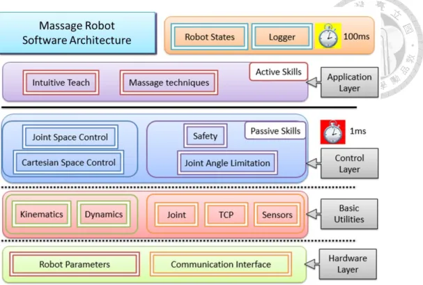
2.5 Software Architecture
Fig. 2-10 presents the software architecture of the dual arm robot. All the control algorithms are written in C++ language under Microsoft Visual Studio 2010. There are many useful open source libraries can be used for robotic kinematics and dynamics such as Robotics Library and Eigen. The robot parameters defined in hardware layer and the functions of communication interface are to send torque command and receive encoder feedback. The information of tool center point (TCP) can be calculated through forward kinematics in basic utilities and the dynamics which is important for robot control is deal with in this layer as well. Based on the basic utilities, Cartesian space impedance control and joint space control are able to be implemented in control layer. These 3 layers are updated every 1ms for real time control. Finally, the massage techniques and intuitive teach are achieved by application layer. The information about the robot state and the values of each joint is displayed with 100ms timer.
Fig. 2-10 The software architecture of the dual arm robot.
Chapter 3 Control Techniques
In this section, we give an overview of the control techniques applied to robotics massage system. The Cartesian impedance control and joint impedance control which are implemented to achieve the movements of massage are presented first. The impedance control models the external environment as a mass-spring-damper system as shown in Fig. 3-1. Its input is position and output is force. Then the online trajectory generator and gravity compensation of the robot are introduced. Finally, a variety of massage technique are illustrated.
Fig. 3-1 The mass-spring-damper system.
3.1 Cartesian Impedance Control
To ensure safety, we adopt impedance control to implement the massage function and develop different massage techniques based on it.
The manipulator dynamic equation of the robot is given by (3.1).
𝑀(𝑞)𝑞̈ + 𝐶(𝑞, 𝑞̈) + 𝐺(𝑞) = 𝜏 + 𝜏𝑒𝑥𝑡 (3.1) where 𝑀(𝑞) is inertia matrix of the manipulator, 𝐶(𝑞, 𝑞̈) is Coriolis and centrifugal matrix, and 𝐺(𝑞) represents the gravity term. 𝑞 is the vector of joint angle. 𝜏 and 𝜏𝑒𝑥𝑡 represent the torque out and the external torque from the environment.
The technique of impedance control [31] considers the external force 𝐹𝑒𝑥𝑡 as a mass-spring-damper system as:
𝐹𝑒𝑥𝑡 = 𝑀𝑒𝑥̃̈ + 𝐷𝑒𝑥̃̇ + 𝐾𝑒𝑥̃ (3.2) 𝑀𝑒, 𝐷𝑒, and 𝐾𝑒 are the matrix of mass, damper and spring of the environment respectively. 𝑥̃ represents the displacement of outside environments (Fig. 3-2) as follow:
𝑥̃ = 𝑥 − 𝑥0 (3.3)
where 𝑥0 is the equilibrium position and 𝑥 is the real position encountering the external force.
The relation between the external torque and the external force is shown as (3.4). 𝐽 is the Jacobian matrix of the manipulator.
𝜏𝑒𝑥𝑡 = 𝐽𝑇𝐹𝑒𝑥𝑡 (3.4)
Therefore, the Impedance Control law can be derived as:
𝜏 = 𝑀(𝑞)𝐽(𝑞)−1{𝑀𝑒−1[𝐹𝑒𝑥𝑡− 𝐷𝑒𝑥̃̇ − 𝐾𝑒𝑥̃] − 𝐽̇(𝑞)𝑞̇}
+𝐶(𝑞, 𝑞̈) + 𝐺(𝑞) − 𝐽𝑇𝐹𝑒𝑥𝑡
(3.5)
Fig. 3-2 The schematic diagram of manipulator with external environment.
3.2 Joint Impedance Control
Because it is difficult to give the command in Cartesian space for some massage techniques, we also adopt the joint impedance control in the robot system. Joint impedance control [32] can give the command in joint space while keep compliance. It is used to achieve the lead-through capability that users are able to teach the desired trajectory by leading the robot arms themselves.
From the electric and mechanical dynamics of the motor and joint, the basic equations are formulated as follow:
𝐿𝑑𝑖
𝑑𝑡+ 𝑅𝐼𝑒 = 𝑉 − 𝑉𝑏 (3.6)
𝐽𝑚𝑞̈ + 𝐶𝑚𝑞̇ = 𝜏𝑙𝑜𝑎𝑑 − 𝜏𝑑 (3.7)
where 𝐿 and 𝑅 are motor inductance and resistance, 𝐼 and 𝑉 are current and voltage, 𝐽𝑚 and 𝐶𝑚 are inertial of system load and viscosity coefficient, 𝑉𝑏 and 𝜏𝑑 are back EMF voltage and disturbance torque and 𝜏𝑙𝑜𝑎𝑑 is the load torque.
If 𝑅 ≫ 𝐿 (𝜏 = 𝐾𝑚𝐼, 𝑉𝑏= 𝐾𝑏𝑞̇), the load torque 𝜏𝑙𝑜𝑎𝑑 can be obtained as:
𝜏𝑙𝑜𝑎𝑑 = 𝐽𝑚𝑞̈ + (𝐶𝑚+𝐾𝑚𝐾𝑏
𝑅 ) 𝑞̇ + 𝜏𝑑 (3.8)
And the impedance control law can be described as:
𝜏 = 𝐾𝑖𝑚(𝑞𝑟− 𝑞) + 𝐷𝑖𝑚(𝑞̇𝑟− 𝑞̇) + 𝐽𝑚𝑞̈ + (𝐶𝑚+𝐾𝑚𝐾𝑏
𝑅 ) 𝑞̇ + 𝜏𝑑 (3.9) where 𝐾𝑖𝑚 and 𝐷𝑖𝑚 are the proportional and derivative impedance gains, and 𝑞𝑟 is desired angular position.
3.3 Online Trajectory Generator
Due to the of impedance control, when the desired position is far from the actual
on the other hand, when the actual position is very near to the desired position, the output toque will be too small which cause the error between these two position. To conquer this problem, we add the online trajectory generator in the Cartesian impedance control so that the speed of the robot motion can be regulated.
The speed of a trajectory can be divided into three phases including acceleration phase, uniform phase and deceleration phase as shown in Fig. 3-3.
Fig. 3-3 Three phases of online trajectory generator.
In the acceleration phase, the speed of the robot arm is limited to prevent from exceeding the maximum acceleration. It is presented as:
𝑖𝑓 𝑥̇ > 𝑥̇𝑡−1+ 𝑥̈𝑚𝑎𝑥𝑡
𝑡ℎ𝑒𝑛 𝑥̇0 = 𝑥̇𝑡−1+ 𝑥̈𝑚𝑎𝑥𝑡
(3.10)
where 𝑥̈𝑚𝑎𝑥
is the maximum acceleration/deceleration in on-line trajectory generator.
𝑥̇ is the actual velocity, 𝑥̇𝑡−1 is the velocity at last sampling time and 𝑥̇0 is planned velocity.
In the uniform phase, the arm motion goes with uniform speed. Its speed can be constrained as:
𝑖𝑓 𝑥̇ > 𝑥̇𝑚𝑎𝑥 𝑡ℎ𝑒𝑛 𝑥̇0 = 𝑥̇𝑚𝑎𝑥 (3.11)
Finally, when the actual position is close to desired position, the arm motion enters deceleration phase. It can be presented as:
𝑖𝑓 𝑥̇ > √2𝑥̈𝑚𝑎𝑥𝑆 𝑡ℎ𝑒𝑛 𝑥̇0 = √2𝑥̈𝑚𝑎𝑥𝑆 (3.12)
Fig. 3-4 shows the control diagram of Cartesian impedance control. The encoder feedback is transformed to the current position, velocity, and acceleration as the input of trajectory generator. Then the planed positon can be obtained with:
𝑥𝑝 = 𝑥𝑡−1+1
2(𝑥̇0+ 𝑥̇𝑡−1)𝑡 (3.13)
Fig. 3-4 The control diagram of Cartesian impedance control.
3.4 Gravity Compensation
For gravity compensation, the compensation torque is computed by calculating Jacobin matrix in each configuration of the manipulator. The Jacobian transpose is described in (3.14).
𝜏 = 𝐽𝑇𝐹 (3.14)
From the definition of Jacobian, the velocity in Cartesian coordinate 𝑥̇ can be presented by the angular velocity in joint space 𝑞̇ and the Jacobian matrix (3.15).
𝑥̇6×1 = [𝑉3×1
𝜔3×1] = [𝐽𝑉(𝑞) 𝐽𝜔(𝑞)]
6×𝑛
𝑞̇𝑛×1 (3.15)
where 𝐽𝑉(𝑞) and 𝐽𝜔(𝑞) are determined as follow:
𝐽𝑣(𝑞) = 𝑃(𝑞)̇ (3.16)
𝐽𝜔 = [ 𝑅1 𝑧 2𝑅𝑧 ⋯ 𝑛𝑅𝑧] (3.17)
where 𝑛𝑅𝑧 represents the z-axis component in transformation matrix 𝑛0𝑇 which is shown as:
𝑛0𝑇= [ 𝑅𝑛0 𝑛0𝑃
0 1 ] (3.18)
Then the gravity compensation can be achieved by (3.18) and properly defining the center of gravity and mass of each link.
3.5 Massage Techniques
There is a variety of massage techniques realized by our dual arm robot such pressing, rubbing, stroking, and tapping. We will focus on the first 3 techniques in this section.
3.5.1 Pressing
Pressing is a technique to perform the periodical pressing movement on a single point. Its force 𝐹𝑝𝑟𝑒𝑠𝑠𝑖𝑛𝑔 is determined by the impedance parameters and the virtual target point 𝑥0. Its function can be expressed as below:
𝐹𝑝𝑟𝑒𝑠𝑠𝑖𝑛𝑔(𝑥0, 𝑡) = 𝐹𝑒𝑥𝑡(𝑥0)𝛺(𝑡) (3.19)
𝐹𝑒𝑥𝑡(𝑥0) represents the amplitude in periodical movement. 𝛺(𝑡) as defined in (3.20) is the sigmoid function that determines the pressing time and the indentation speed. 𝜂 is the time constant used for waiting the rising and falling edges; 𝑇 is the pressing time after reaching the desired pressing force from (3.19) and 𝑎 is the index for the designed sigmoid function.
𝛺(𝑡) = {
1
1 + 𝑒−𝑎(𝑡−𝜂2), 0 ≤ 𝑡 < 𝜂 1, 𝜂 ≤ 𝑡 < 𝜂 + 𝑇
1 1 + 𝑒𝑎(𝑡−3𝜂2 −𝑇)
, 𝜂 ≤ 𝑡 < 𝜂 + 𝑇
(3.20)
3.5.2 Rubbing
Rubbing is the technique that uses palm or thumb to apply pressure maintained on the human skin. It moves by following a circular trajectory to loosen the tight muscles.
The same as pressing, we need to determine the virtual target point for generating proper rubbing force. Its motion can be realized by (3.21).
𝑥0 = [ 𝑥 𝑦
𝑧] = [ 𝑟𝑐𝑜𝑠𝜃 𝜆1(−𝑥 + 𝜆2)
𝑟𝑠𝑖𝑛𝜃
] (3.21)
where 𝑥0 is the planed position, 𝑟 is the radius of circular motion, 𝜃 is the incremental angle of rubbing technique and both 𝜆1 and 𝜆2 are the coefficients to compensate the slope of human back.
3.5.3 Stroking
Stroking is a long and smooth movement with moderate pressure over large range of the body. Since the profile of the human body is varied from person to person and the stroking technique needs to maintain the moderate contact force along the profile of body, the stroking trajectories are taught by the masseur that intuitively moves the robot arms in order to repeat the motion when performing the stroking technique. Joint impedance control which is presented in 3.2 is used to achieve the stroking technique.
The trajectory of stroking will be saved in the storage as a sequential command in joint space.
Chapter 4 Low-Cost Laser Range Finder
There have been researches discussing massage trajectory planning, but they often generate the trajectories through teach and play or user interface. Those are not an automated process and unsuitable for different body shapes. Another stumbling block for massage robots is the sensors which are indispensable to robotics service applications. In order to generate the massage trajectory accurately without other people’s help and lower the cost at the same time, we propose an adaptive trajectory generation system by using a self-developed low-cost laser range finder (LRF) that can get the 3D information with a single scan. In this chapter we firstly introduce the hardware and software system of the self-developed laser range finder; then the laser based line scanner module which is applied on the LRF is presented. We prove the performance by comparing the accuracy of the self-developed LRF and the commercial product and scan lots of objects to show its capability as well.
4.1 System Description
Fig. 4-1 shows the structure of the self-developed laser range finder. It has the following specifications.
1) Size of 270[mm]x75[mm]x105[mm]
2) Eye-safe (Class II)
3) Measurable Range: 0.35[m]~4[m] for distance measurement ( 0.35[m]~1.75[m] for adaptive trajectory generation)
4) High Resolution: 7.35[mm] range resolution at 1.75[m]
5) Wide Scanning Range: 300[deg] with angular resolution of 0.29[deg]
6) Scanning Time: 400[ms/deg]
7) Extracting 3D information with a single scan 8) Low Cost: less than 70USD to build
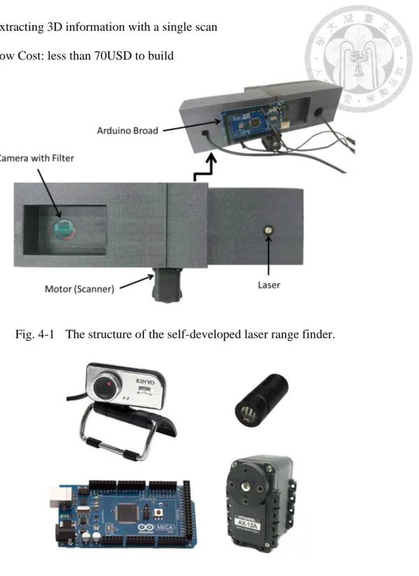
Fig. 4-1 The structure of the self-developed laser range finder.
Fig. 4-2 The components of the self-developed laser range finder.
The laser range finder is composed of a line laser, a commercial camera which communicates with the computer through USB, a Dynamixel AX-12A motor from Robotis for yaw rotation, and an Arduino for motor control and data transmission (Fig.
4-2). The camera and motor is synchronized through software (Fig. 4-3). The time
difference of synchronization is 0.12s. Because the rotation speed of the motor is not fast (400ms/deg), we still can capture corresponding image from camera. It is acceptable in this application. Our LRF system performs on a Windows 7 64bit i5-4460 3.20GHz with 16GB RAM. The total power consumption is about 1.525W. It should work just as well on smaller or mobile platforms like the Raspberry Pi. All components are commercial products bought online. Their prices are shown in Table 4-1. The total price is 69 USD which is less than 10% of the price of the commercial product such as SICK and Hokuyo. Its aggregate price can be much lower after it enters the mass production stage.
Fig. 4-3 The block diagram of the electronic components.
Component Product Type Price (USD)
Line Laser FU635L5-C9 3
USB Camera + Filter KINYO PCM-512 16
Motor Robotis Dynamixel AX-12A 40
Circuit Board Arduino mega 2560 10
Total: 69 Table 4-1 The price and the product type of the component.
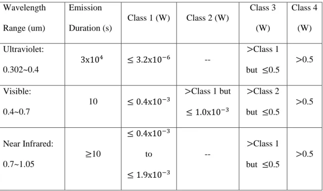
There is a tradeoff between getting better performance and maintaining safety. To
ensure the eye safety, we should choose the laser which doesn’t cause the eyes harm.
The power level of laser is divided into 4 classes. Class 1 means it is safe under all conditions of normal use and Class 2 represents the laser damages to the retina can be prevented by the blink reflex (0.25 seconds exposure time). The class above Class 3 will have the high risk of serious damage to eyes. Table 4-2 shows the accessible emission limits for laser systems formulated by ANSI Z136 [33] which provides guidance for the safe use of lasers and laser systems. The wavelength of the line laser is 635nm (visible light) that is easier to debug and calibrate than IR wavelengths, so we pick 1mW for the power of laser which is able to acquire the best results with keeping eyes safe. In the future, we will change the light source to near infrared ray to give the user a more comfortable sensory experience.
Wavelength Range (um)
Emission Duration (s)
Class 1 (W) Class 2 (W)
Class 3 (W)
Class 4 (W) Ultraviolet:
0.302~0.4
3x10⁴ ≤ 3.2x10⁻⁶ --
>Class 1
but ≤0.5 >0.5 Visible:
0.4~0.7
10 ≤ 0.4x10⁻³
>Class 1 but
≤ 1.0x10⁻³
>Class 2
but ≤0.5 >0.5
Near Infrared:
0.7~1.05
≥10
≤ 0.4x10⁻³ to
≤ 1.9x10⁻³
--
>Class 1 but ≤0.5
>0.5
Table 4-2 Emission limits for laser systems
In most environments, the received laser is affected by ambient light. There are 3 methods usually used to reject the ambient light as below. The first method is not suitable for outdoor environment because of sun light and the second method cannot
deal with the environment that has the fluorescent lamp. Because of the aforementioned reasons and cost consideration, we select the third one and add a 30nm bandpass filter to reduce the ambient light flux. The camera with filter has capability of not to capture clear images from people for avoiding privacy issues.
1) Adjusting the exposure time of camera 2) Using IR light as laser source
3) Adding Filter
4.2 Laser Based Line Scanner Module
Laser based line scanner module is developed from laser point sensor module [18]
which is based on triangulation technology. Most of commercial products such as SICK and Hokuyo devices use time-of-flight (TOF) technology. They measure the time it takes for light to travel to an object and be reflected. The disadvantage of time-of-flight is that its receiver is very expensive and it often takes mirror as scanner of which cost and mechanical fragility are high. An alternative technology is triangulation. Its principle is that the distance to an object is measured by the angle of the reflected light and we can replace mirror with motor as scanner to cost down.
Fig. 4-4 shows the triangulation geometry of single-point laser sensor module. A laser produces a small point of light, which reflects off an object and onto the image plane of the camera. To give an ideal distance measurement from infinity, the laser beam needs to be parallel to the ray through the center of focus to the one edge of the image. The other edge of the image determines the minimum distance 𝑞𝑚𝑖𝑛.
The perpendicular distance 𝐷 to the target according to basic triangulation principle can be calculated as follow:
![[CSIE 5521] Wireless Networking: Fundamentals and Applications](data:image/gif;base64,R0lGODlhAQABAIAAAP///wAAACH5BAEAAAAALAAAAAABAAEAAAICRAEAOw==)