3D ENVIRONMENT MODELING AND MONITORING USING KINECTS FOR VIDEO SURVEILLANCE 1
Bing-Chen Ma (馬秉辰)
Institute of Computer Science and Engineering National Chiao Tung University, Hsinchu, Taiwan
Email: [email protected]
2Wen-Hsiang Tsai (蔡文祥)
Dept. of Computer Science
National Chiao Tung University, Hsinchu, Taiwan Email: [email protected]
Abstract―Methods for 3D environment modeling and monitoring for video surveillance using an octago- nal-shaped 9-KINECT imaging device are proposed.
Firstly, an environment modeling method is proposed which converts KINECT images into 3D images. Then, a human tracking method is proposed, in which the handoff problem between KINECT devices is also solved. Finally, a human modeling method is proposed, by which se- quences of 3D images constructed from KINECT images may be integrated to form human models. Human fea- tures like body height, width, and thickness may be ex- tracted from the model for use in security monitoring and off-line video search. Good experimental results are also shown to prove the feasibility of the proposed methods for real applications.
Index Terms―KINECT, data conversion, calibration, human detection, human tracking, human modeling.
I. I
NTRODUCTIONIn recent years, uses of 3D image-data sensing devic- es like KINECTs become popular. Such devices can capture not only RGB color images and audio data but also depth information in the meantime. With the depth information, we can translate the captured data into 3D images which are beneficial to researches on topics like 3D object detection, modeling, etc. So, in this study it is desired to design a 3D video surveillance system using multiple KINECT devices for indoor applications: (1) monitoring an indoor environment and displaying the captured images in 3D manners for users to inspect the recorded environment data from different viewpoints; (2) using the depth information to detect and track human activities and providing changes of viewpoints from different KINECT devices; (3) creating human models
1 This research was supported by the NSC, Taiwan under Grant No. 101-2221-E-009-146-MY3.
2 W. H. Tsai is also with the Department of Information Communication, Asia University, Taichung, Taiwan 41354.
when users browse the data acquired by KINECTs, and providing the features of the humans such as height, body width, body thickness, etc., for various purposes.
Many modeling techniques have been proposed by using data acquired from KINECTs. Shahram [1] pro- posed a technique, called KinectFusion, which uses the depth information acquired by moving the KINECT device to build up a high-quality and geometrical- ly-precise 3D model quickly. Henry [2] proposed a 3D mapping system which uses visual features and a shape-joint optimization algorithm with RGB color im- ages and depth information acquired with KINECTs. In addition, many algorithms have been proposed for mo- tion detection and tracking. Chaiyawatana [3] con- structed an automatic system for vehicle detection by frame subtraction. Xia [4] used depth information pro- vided by KINECTs to conduct 2D chamfer matching and adopted some human features to figure out human shapes for human activity tracking. Meltem [5] pro- posed a standard video tracking and person classifica- tion system. Pantrigo [6] studied, by use of a video pro- cessing system, human activities under different situa- tions such as sports and video surveillance.
To reach the goal of this study mentioned above, at first we construct a new device for use as a 3D video surveillance system, which is composed of nine KI- NECTs, called an octagonal 9-KINECT imaging device.
Then, KINECT data integration is conducted, including converting the depth information acquired by the device into 3D data form. Next, with the 3D data, calibration of the spatial relations between the KINECT devices is performed. And the calibration result is used to con- struct an indoor environment model. Subsequently, de- tection and tracking of human activities dynamically are conducted. Finally, the recorded data from KINECT devices are used to create human models and extract features from them.
In the remainder of this paper, the design of the oc- tagonal 9-KINECT imaging device will be described in
Section 2, the conversion of KINECT data into 3D im-
ages, and correction of the conversion result presented in Section 3. The calibration of KINECT devices and indoor environment modeling will be introduced in Sec- tion 4, and human detection and tracking methods in- troduced in Section 5, followed by human modeling in Section 6. Some conclusions are given in Section 7.
II. D
ESIGN OFA
NO
CTAGONAL9-K
INECTI
MAGINGD
EVICEIt is desired to use multiple KINECT devices 3D video surveillance, so an octagonal 9-KINECT imaging device is designed in this study, which is shown in Fig.
1(a). Specifically, eight KINECTs are affixed around a octagonal-shaped steel cage to cover a full view of the surround with a certain degree of overlapping, and one additional downward-looking KINECT is added inside the steel cage to take care of the missing part of the en- tire field of view (FOV), as illustrated in Fig. 1(b).
(a) (b)
Fig. 1 The octagonal 9-KINECT imaging device de- signed for use in this study. (a) The exterior appear- ance. (b) The placement of the 9 KINECT devices.
Each KINECT device can change its vertical tilt an- gles from 27o to 27o. So the vertical tilt angle of the outer 8 KINECT devices on the interchangeable bases ranges from 3o to 57o. The maximum sensing dis- tance to acquire a depth image is 4 meters which is de- cided by the Kinect-for-Windows SDK provided by Microsoft. An illustrative diagram of the coverage of views is shown in Fig. 2.
Fig. 2 The coverage of views by the depth image seen from the side view.
Secondly, about the imaging speed, we acquire image data by the 9 KINECT devices sequentially. When we acquire the data of a video frame consisting of a color image and a depth image by a single KINECT device, the frame rate is 30 fps. So the overall frame rate to ac-
quire all the color and depth images of the nine KI- NECT devices is 3.37 fps. But we assume that the mon- itored object or human does not move too fast, so it will not be a problem to our processing work.
III. C
ONSTRUCTIONOF3D I
MAGES FROMK
I-NECT
I
MAGESThe data acquired by a KINECT device consists of a color image and a depth image, which are called KI- NECT images. The KINECT images are not 3D in na- ture, so we construct a corresponding 3D image from each pair of such KINECT images. The 3D image con- tains three kinds of data. One is color data which come from the color image. Another is 3D data which is ob- tained by converting the depth image into a 3D version.
The third is a mapping array, which is obtained by using the Kinect-for-Windows SDK provided by Microsoft and is used as a tool for combining the former two parts.
A. Construction of 3D Data from Depth Image We use the pinhole camera model [7] to convert depth image into 3D data. The pinhole camera model de- scribes the mathematical relationship between the coor- dinates of a 3D point and its projection on the image plane of the pinhole camera, as shown in Fig. 3. From Fig. 3(b), we can derive the following equation accord- ing to the similar-triangle principle:
3 1 1
x x f
y
. (1)
When we look in the negative direction of the X1-axis, the following equation can be derived similarly:
3 2 2
x x f
y
. (2)
Summarizing these two equations, we get:
2 1 2 3
1
x x x
f y
y (3)
which describes the relation between the space coordi- nates (x1, x2, x3) of a 3D point P and the image coordi- nates (y1, y2) of the corresponding 2D projection point Q.
(a) (b)
Fig. 3 The geometry of a pinhole camera model. (a) Seen from a 3D point. (b) Seen from the X2-axis.
From Eq. (3), we get:
1 3
1 y
f
x x (4)
2 3
2 y
f
x x (5)
f f
x3x3 (6)
and from Fig. 3(a) and by the similar-triangle principle again, we have the equation:
22 2
2 1
2 3 2 2 2 1 3
f y y
x x x f x
(7)
where y12 y22f2 is the length of the line segment
OQ, and x12x22x32 is the length of the line segment OPwhich is the depth captured by KINECT device, and is denoted as d in the sequel. Let R present the center of the depth image. It is located at coordinates (320, 240) in a depth image of resolution 640480 acquired by the KINECT device. And let Q be located at image coordi- nates (xp, yp) and let y1 and y2 represent the distances to the center Q in the vertical and horizontal directions, respectively. The letter f denotes the focal length of the KINECT device with its value being 600. The equations (4), (5), (6), and (7) can be rewritten, according to the mentioned parameter values, to be:
2
2 23
600 240
320
p
p y
x
d f
x (8)
320
600 240
3202 2 2
1
p
p p
x y
x
x d (9)
240
600 240
3202 2 2
2
p
p p
y y
x
x d (10)
320
2 240
2 6002 6003
p
p y
x
x d . (11)
With the above equations, we can convert the depth im- age into 3D data and convert the KINECT images to a 3D image with color data and the mapping array. An example of constructed 3D images is shown in Fig. 4.
B. Geometric Correction of 3D Images
After constructing 3D images, a bending phenome- non can be seen to exist in the constructed 3D image. To remedy this, a paraboloid equation is adopted to ap- proximate the curved surface formed in the 3D image.
Then, by using equation, the curved surface can be cor- rected.
In more detail, let the paraboloid equation be:
2 2
paraboloid
z A x B y C. (12)
The sum of square errors (SSE) using Eq. (12) as an approximation of the input data is:
2640 480
2 2
0 i i i
i
SSE z A x B y C
(13)
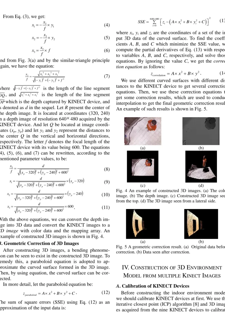
where xi, yi and zi are the coordinates of a set of the in- put 3D data of the curved surface. To find the coeffi- cients A, B, and C which minimize the SSE value, we compute the partial derivatives of Eq. (13) with respect to variables A, B, and C, respectively, and solve those equations. By ignoring the value C, we get the correc- tion equation as follows:
2 2
correlation
z A x B y . (14)
We use different curved surfaces with different dis- tances to the KINECT device to get several correction equations. Then, we use these correction equations to get some correction results, which are used to conduct interpolation to get the final geometric correction result.
An example of such results is shown in Fig. 5.
(a) (b)
(c) (d)
Fig. 4 An example of constructed 3D images. (a) The color image. (b) The depth image. (c) Constructed 3D image seen from the top. (d) The 3D image seen from a lateral side.
(a) (b)
Fig. 5 A geometric correction result. (a) Original data before correction. (b) Data seen after correction.
IV. C
ONSTRUCTIONOF3D E
NVIRONMENTM
ODEL FROMMULTIPLEK
INECTI
MAGESA. Calibration of KINECT Devices
Before constructing the indoor environment model, we should calibrate KINECT devices at first. We use the iterative closest point (ICP) algorithm [8] and 3D imag- es acquired from the nine KINECT devices to calibrate
the spatial relations between the nine KINECT devices.
Before starting calibration, we prepare some calibration targets to assist the calibration process and define a cal- ibration order for the nine KINECT devices. An illustra- tion of the calibration order is shown in Fig. 6 by which we calibrate two neighboring KINECT devices using the ICP algorithm every time. This process is repeated for eight times, resulting in eight transformations.
Fig. 6 The calibration order for the nine KINECT devices.
B. Environment Model Construction
After calibration, we start to construct the indoor en- vironment model. We let the central KINECT device as a pivot and the other KINECT devices being merged to the result of the pivot. By an order identical to the above-mentioned calibration order, we merge two 3D images from two neighboring KINECT devices with corresponding transformation from the calibration re- sults every time. After this process is repeated for eight times, we get the desired model construction result. An example of such results is shown in Fig. 7, which is a top view of a rest area of a lab environment.
Fig. 7 A result of indoor environment model construction.
V. H
UMANT
RACKINGBYT
ILTINGK
INECTSA. Human Detection
Before human tracking can be conducted, we should detect human activities at first. Because the depth image can be considered as a gray-level image, we apply the background subtraction technique to detect human re- gions in the depth image under two assumptions: (1) the indoor environment does not change all the time; and (2) the motion objects in the environment are humans.
To conduct background subtraction, we should
“learn” the background at first. Because it is desired to track human activities dynamically and because the ver- tical tilt angle of the KINECT device may change from
25o to 55o from time to time, the background ap-
pearing in the captured image will change sometimes as well. Accordingly, we conduct background learning by increment steps of 2 degrees of the vertical tilt angle from 25o to 55o for the outer eight KINECT devices.
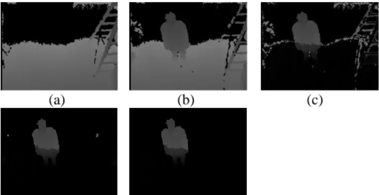
After background learning, we start to detect hu- man regions in the images. For every KINECT device, when a new depth image comes, we subtract it from the background depth image and get a difference depth im- age. Next, we apply mathematical morphology opera- tions to the difference depth image to get a result which still has many fragments. Then, we apply region grow- ing with a suitable threshold to it to find human regions in it. If one of the nine KINECT devices detects human activities by this way, then the device will be marked as a tracking KINECT device; else, the nine KINECT de- vices are kept to continue the human detection task. An example of the intermediate results of human detection is shown in Fig. 10.
(a) (b) (c)
(d) (e)
Fig. 8 An example of human detection results. (a) Back- ground depth image. (b) A new incoming depth image. (c) Result of background subtraction. (d) Result of mathematical morphology operations. (e) Result of region growing.
B. Human Tracking
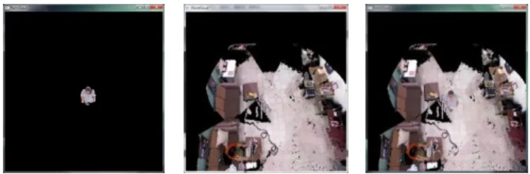
After human detection, we get a tracking KINECT device. When we use the tracking KINECT device to track human activities, we get a series of multiple depth images. Then, we remove the background from these images and convert the results into 3D data. Then, we analyze these 3D data in accordance with the frame rate of the tracking KINECT device to get the moving ve- locity and direction of the human. With such infor- mation, we can predict the next position of the human, and the tilt angle of the tracking KINECT device can be adjusted accordingly to track the human or to conduct handoff to any of the other eight KINECT devices if the human goes out of the FOV of the tracking KINECT device. An example of human tracking is shown in Fig.
9.
More details of the tracking process are as follows.
1. If the predicted position is still in the FOV of the
tracking KINECT device (abbreviated as TKD sub- sequently), then let the TKD keeps the tracking task.
2. If the predicted position is in the FOV of the TKD with a different tilt angle, then change the tilt angle of the TKD to keep tracking of the human.
3. If the predicted position is in the overlapping FOV area of the TKD and a neighboring KINECT device overlap, then let the neighboring KINECT device be the next tracking device by conducting a handoff procedure.
4. If the predicted position is out of the FOVs of all the nine KINECT devices, then go back to the human detection process.
(a) (b) (c)
(d) (e) (f)
Fig. 9 The 3D image sequences of tracking a human.
VI. H
UMANM
ODELINGANDD
ISPLAYOFH
UMANA
CTIVITIESWhen we use the tracking KINECT device, we get many KINECT image sequences because of the handoff process. We store those sequences and the related map- ping array sequences for human modeling as described next.
A. Human Modeling from a Single KINECT Device For each KINECT image sequence, we remove the background from each depth image and leave only the human. Then, we convert the depth image sequence which includes the human into a 3D data sequence. Be- cause the 3D data sequence is recorded with the time sequence, each human in the 3D data sequence is locat- ed at a different position with a small distance from each other depth image. We want to find some trans- formations which can be used to merge every two con- secutive human regions in the 3D data sequence. And then, we can extend these transformations to merge all the human regions in the 3D data sequence to construct a complete human model. We use distance-weighted
correlation (DWC) measure [9] and the k-d tree struc- ture to assist the task of finding these transformations.
After finding these transformations, we let the first human region in the 3D data sequence as a pivot and merge the others into the first human region. A merge example is shown in Fig. 10.
(a) (b)
Fig. 10 A human model construction result from a 3D data sequence. (a) A 3D data sequence containing a human where the arrow indicates the walking direction. (b) Hu- man model constructed by merging human regions in the 3D data sequence.
B. Merging Human Models from Multiple KINECTs After we merge each 3D data sequence individually, we get several human models. Because each human model comes from a different KINECT device, we should calibrate the spatial relation between these hu- man models. Luckily, we have calibrated the spatial re- lation between the nine KINECT devices as described previously, so we can use the calibration results directly and convert those human models into an identical view.
With the human models displayed in the same view, there still exists some distances between the models. So we use the DWC and the K-d tree structure again to as- sist the task of finding transformations between these human models. Afterwards, we start to merge all human models. For this, we use the first human model as a piv- ot and merge the other models into it. A result of this process is shown in Fig. 11.
(a) (b)
(c) (d)
Fig. 11 An example of merging human models (a) and (b) are human model merged from different 3D data sequence. (c) Applying the calibration result to the two human models. (d) Merging result of the two human models.
C. Merge of Human Model and 3D Background
Because we assume that the indoor environment is always static, we can merge the background model and the human model directly. An example of the merging result is shown in Fig. 12.
(a) (b) (c)
Fig. 12 An example of human model and background merg- ing result. (a) The human model. (b) The background model.
(c) The merge result.
D. Extraction of Human Features
With the human model constructed, we can analyze the human model to get some features of the human such as height, body width, body thickness, etc. for var- ious applications. Though these features may not be ac- curate because of the moving actions of the human ac- tivities, they are still useful for security monitoring and person identification purposes. An example for extract- ing human features from the human model is shown in Fig. 13.
Fig. 15 An example of human feature extraction from the human model. The red frames are used to compute the approximate human features like height, body width and body thickness.
VII. C
ONCLUSIONSIn this study, a system for 3D environment modeling and monitoring via KINECT images using an octagonal 9-KINECT imaging device for video surveillance has been proposed. To implement such a system, several methods and strategies have been proposed, including:
(1) a method based on the pinhole camera model for converting KINECT images into 3D images; (2) a method for geometric correction for removing the bending phenomenon existing in the 3D image con- structed from KINECT images; (3) a method for cali-
bration of spatial relations between KINECT devices based on the concept of the ICP, whose results are used to build up indoor environment models; (4) a method for constructing indoor environment models, which uses the calibration results and the 3D images converted from the KINECT images to construct indoor environ- ment; (5) methods for background learning, human de- tection, and human tracking with the handoff problem solved; (6) a method for human modeling using the DWC measure and the k-d tree structure. The experi- mental results shown have revealed the feasibility of the proposed methods.
R
EFERENCES[1] Shahram Izadi, Richard Newcombe, David Kim, Ot- mar Hilliges, David Molyneaux, Steve Hodges, Pushmeet Kohli, Jamie Shotton, Anderw Davison and Andrew Fitzbiggon, “KinectFusion: Real-Time Dy- namic 3D Surface Reconstruction and Interaction, ” ACM SIGGRAPH Talks 2011.
[2] P. Henry, M. Krainin, E. Herbst, X. Ren, and D. Fox,
“RGB-D Mapping: Using depth cameras for dense 3D modeling of indoor environments,” in the 12th International Symposium on Experimental Robotics (ISER), December 2010.
[3] N. Chaiyawatana, B. Uyyanonvara, T. Kondo, P.
Dubey and Y. Hatori, “ Robust object detection on video surveillance,” 2011 8th Int’l Joint Conf. on Computer Science & Software Engineering (JCSSE), Nakhon Pathom, pp. 149 - 153, May 2011.
[4] L. Xia, C. -C. Chen and J. K. Aggarwal ,“Human De- tection Using Depth Information by Kinect,” in IEEE Int’l Workshop on Human Activity Understanding from 3D Data in conjunction with CVPR (HAU3D), Colorado Springs, pp. 15-22, June 2011.
[5] D. Meltem, G. Kshitiz, and G. Sadiye, “Automated person categorization for video surveillance using soft biometrics,” Proceedings of the SPIE, vol. 7667, pp.
76670P-76670P-12, 2010.
[6] J. J. Pantrigo , J. Hernández and A. Sánchez, “Multi- ple and variable target visual tracking for vid- eo-surveillance applications, ” Pattern Recognition Letters, vol.31, no. 12, pp. 1577-1590, 2010.
[7] Wikipedia, “Pinhole camera model,” March 2013.
http://en.wikipedia.org/wiki/Pinhole_camera_model.
[8] Wikipedia, “Iterative closest point,”May 2013.
http://en.wikipedia.org/wiki/Iterative_closest_point [9] T. C. Fan and W. H. Tsai (1984). "Automatic Chinese
seal identification," Computer Vision, Graphics, and Image Processing, Vol. 25, pp. 311-330.