DATA HIDING IN GRAYSCALE IMAGES BY DYNAMIC PROGRAMMING BASED ON A HUMAN VISUAL MODEL
1,# I-Shi Lee (李義溪) and 1,2 Wen-Hsiang Tsai (蔡文祥)
1Dept. of Computer Science, National Chiao Tung University
2Dept. of Computer Science and Information Engineering, Asia University E-mail: [email protected] & [email protected]
# Also with the Department of Information Management at Technology and Science Institute of Northern Taiwan.
ABSTRACT
A new method for data hiding in grayscale images based on a human vision model with distortion-minimizing capabilities is proposed for covert communication. Each of the eight bit planes of an input grayscale image is viewed as a binary image, into which message data are embedded horizontally. To minimize the image distortion, two optimization techniques, namely, block pattern coding and dynamic programming, are proposed. Furthermore, the proposed method can predict the PSNR value of the resulting image according to the size of the data to be embedded before the embedding process starts. Experimental results show good performances of the proposed method.
1. INTRODUCTION
Data hiding in images is a useful technique for covert communication. Many data hiding techniques have been proposed recently [1, 2, 3]. The most common approach is least-significant-bit (LSB) replacement, which embeds message data in a subset of the LSB planes of an image. The image into which a message is hidden is called a cover image, and the result a stego-image. Wang et al. [4] embedded a binary image in the fifth LSB bit plane of a cover image, and employed an optimal substitution process based on a genetic algorithm and a local pixel adjustment method to lower the distortion in the stego-image. Chang et al. [5] used dynamic programming to obtain an optimal solution for the LSB substitution method. Chan and Cheng [6, 7] presented an optimal pixel adjustment process to improve the image quality of the stego-image acquired by Wang’s schemes. Thien and Lin [8] proposed a method for hiding data in images digit by digit using a modulus function. The method is better than simple LSB substitution not only in eliminating false contours but also in reducing image distortion. Lee and Chen [9]
applied variable-sized LSB insertion to estimate the maximum embedding capacity by a human visual system (HVS) property, and to maintain image fidelity by removing false contours in smooth image regions. Liu et al. [10] presented a novel bit plane-wise data hiding scheme using variable-depth LSB substitution and employed post-processing to eliminate the resulting noticeable artifacts.
Most of the above methods lack consideration of using precise human visual models in improving the data hiding effect. Instead, Wu and Tsai [11] presented a method based on the HVS by modifying quantization scales according to variation insensitivity from smooth to contrastive to improve the stego-image quality. And Lie and Chang [12] presented an adjusted LSB technique with the number of LSBs adapting to the pixels of different grayscales.
In this study, we propose a method to embed data into a grayscale image for covert communication, based on the use of a new HVS model to estimate the number of usable bits of each pixel in the cover image. Furthermore, a block pattern encoding method is proposed to embed up to three data bits in a 2×2 block of the bit planes without yielding visible degrading of the stego-image quality. This is achieved by using two optimization techniques. The first technique utilizes multiple block pattern encoding tables, from which an optimal one is chosen for each input image, and the second technique uses dynamic programming to divide the message data stream into appropriate bit segments for optimal data bit embedding in the image blocks to minimize a cost function. Especially, the proposed method can predict the PSNR value of the stego- image according to the embedded data size before the embedding process is started. Moreover, the proposed method can extract embedded data without referencing the original image, and does not require post-processing to refine the stego-image quality.
In the remainder of this paper, we introduce the basic idea behind the proposed method in Section 2. In Section 3, we describe the adopted HVS model and the corresponding cost function. In Section 4, the proposed data hiding method is described. The corresponding data recovery process is proposed in Section 5. Some experimental results are given in Section 6, followed by conclusions in Section 7.
2. EMBEDDING DATA IN BIT PLANES OF GRAYSCALE IMAGES
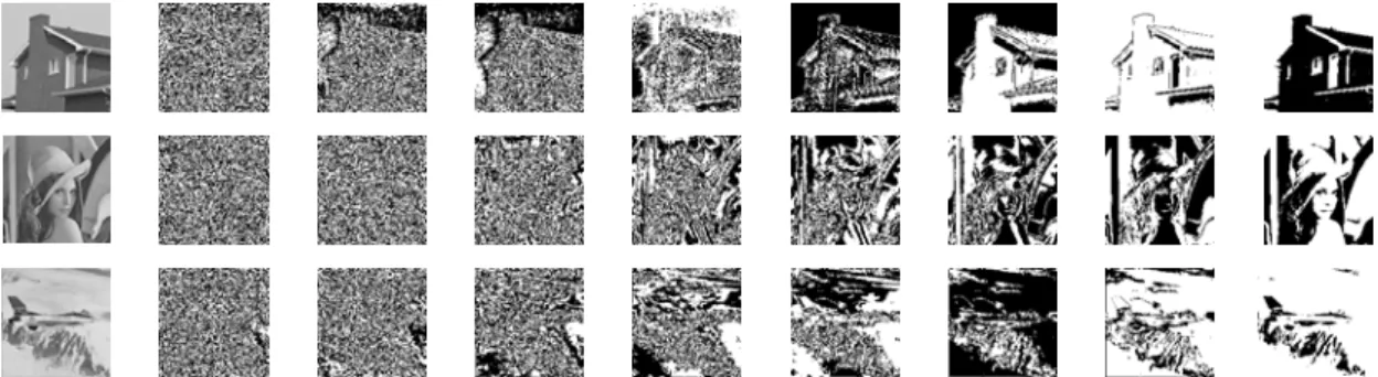
Eight bits represent a pixel’s intensity in a grayscale image. The bit plane formed by the same bit of each pixel in the grayscale image is a binary image. Figure 1 shows the eight bit planes of each of three given 128×128 grayscale
Figure 1. Three grayscale images and their 8 corresponding bit planes (from left to right, original images, bp0, bp1, bp2, …, and bp7, respectively).
images. The image of each bit plane is zoomed out for comparison. It is observed that the content of the LSB plane bp0 is almost fully randomized. If the message is embedded in bp0, the resulting image will appear to be almost unaltered to human eyes. On the contrary, there exist less random noise areas in the remaining more significant bit planes.
The most-significant-bit plane bp7 contains almost no noise, and data cannot be embedded easily into it without causing significant visual changes. We may embed message data into bit planes in the order of bp0, bp1, …, bp7. This scheme is termed horizontal data hiding, to be contrastive with traditional vertical data hiding methods which embed data into the bits b7, b6, …, b0 of each pixel in the order of b0
through b7, where b0 is the LSB of the pixel. Compared with the vertical data hiding method, horizontal data hiding can reduce more distortion in the stego-image, as revealed in the results of this study.
On the other hand, embedding data directly in bit planes will cause visible damages to the edges in the bit planes. To overcome this difficulty, in this study we design a new cost function which considers certain perception characteristics of the HVS, and adopt a method proposed in Lee and Tsai [13]
for data embedding. Each bit plane is regarded to have a different weight in its capability for data hiding, and the new cost function is designed accordingly to measure the degree of distortion resulting from pixel value changes. The details are discussed in the following.
3. COST FUNCTION FOR DISTORTION MEASUREMENT
Since stego-images are viewed by human vision, the characteristics of the HVS must be exploited in designing a data embedding process. Two of such characteristics are useful here. First, human perception is more sensitive to grayscale changes in smooth areas than in texture areas in a grayscale image. Second, human perception is sensitive to relative luminance rather than absolute one. Designing the cost function for distortion measurement for data embedding must take these two characteristics into consideration, as elaborated in the following.
3.1 Computing Number of Data-Embeddable Bits with Consideration of Neighborhood Grayscale Value Change
For the first consideration, assume that a pixel P with grayscale value g is to be used to embed message data. Let MAX denote the maximum grayscale value, and MIN the minimum, in the 3×3 block with P as the center, which we call the neighborhood of P. Then, the maximum between-pixel grayscale range in this block is Δ = MAX − MIN. According to the previous discussions, to avoid a significant change of the
smoothness degree with respect to the neighborhood of P, the new grayscale value g′ resulting from the data embedding is restricted in this study to remain in the range of g ± Δ/2. Then, we define a maximum number D of data-embeddable bits at P as
D = ⎣log2(Δ/2)⎦ = ⎣(log2Δ) − 1⎦ = ⎣log2(MAX− MIN) − 1⎦. (1) 3.2 Computing Number of Data-Embeddable Bits with
Consideration of Pixel’s Luminance Change
For the second consideration mentioned above, let f denote the luminance of a pixel P with grayscale value g where 1 ≤ f
≤ 100. According to the Fechner law [14], the relative luminance property perceived by the HVS may be expressed as a contrast value c computed by
c = 50×log10f
where 0 ≤ c ≤ 100. Moreover, according to the Weber law [14], the maximum allowable change Δc of the contrast value c according to the principle of “just noticeable difference (JND)” about the pixel’s luminance change is about 2. That is, if the luminance of a pixel is changed too much so that Δc is larger than 2, the change will be noticeable to the HVS.
Accordingly, we can compute in another way a maximum number of data-embeddable bits in the 8 bits of a pixel’s grayscale value, as described next.
First, we want to compute the maximum luminance change (Δf)max in accordance with the maximum allowable contrast change (Δc)max = 2. With c being the contrast of pixel P, let cmax denote the maximum possible contrast value. Then, we have
2 = (Δc)max = cmax − c = 50×log10fmax − 50×log10f
= 50×log10 fmax / f,
which can be reduced to be fmax/f = 10(2/50). So, the maximum allowable luminance change can be expressed as
(Δf)max = fmax − f = (fmax/ f − 1)×f = (10(2/50) − 1)×f ≈ 0.0965×f.
And so we may impose the following constraint to the value of f:
(Δf)max/ f ≤ 0.0965. (2) On the other hand, in a monochrome image the luminance f in the range of [1 100] is represented by the grayscale value g in the range [0 255], such that g may be computed by the mapping g = (f − 1)×(255/99) ≈ 2.576(f − 1), or equivalently, the mapping f ≈ 0.3882g + 1, which specifies a linear relation between f and g. Hence, from Constraint (2), we can, after some derivations, get the following new constraint for grayscale changes according to the principle of JND:
0.0965 ≥ (Δf)max/ f = (Δg)max/(g + 2.576) (3) where (Δg)max, corresponding to (Δf)max, denotes the maximum grayscale change in the pixel’s neighborhood. That is, if the above constraint (3) is set for data embedding, the changes of grayscales in the stego-image will not be detectable by human eyes according to the JND principle.
Now, we discuss how many bits can be utilized for data embedding for each possible grayscale value g. If 5 bits of the pixel’s grayscale are used for embedding message data, the maximum grayscale change at the pixel will be (Δg)max = 25 − 1 = 31. And according to Constraint (3), g must be larger than 319, which, however, is out of the grayscale range [0, 255].
This means that embedding 5 or more bits of message data into a pixel is impractical according to the JND principle. As a result, bp4, bp5, bp6, and bp7 are not used for data embedding in this study. If 4 LSBs of g are changed, then (Δg)max = 24 − 1
= 15, and by Constraint (3) we get g >153. That is, when the following constraint g > 153 is satisfied, we can embed data into the 4 LSBs of g without causing a noticeable luminance change according to the JND principle.
However, the binary value of 153 is 100110012. After the 4 LSBs of g are changed, the new value of g might become a value in the range of 100100002 through 100110002, which is smaller than 153, causing a violation of Constraint (3).
Therefore, we must change the above constraint g > 153 to be g > 160 where 160 = 101000002 such that after any 4-bit data are embedded into the 4 LSBs of g, the resulting new value g' of g will always be larger than 160, thus satisfying Constraint (3). In other words, to meet Constraint (3), only when a given pixel’s grayscale g satisfies g ≥ 160 can the 4 LSBs of g be replaced by 4-bit message data. And in short, 4 bits are the upper limit to be embedded in a pixel’s grayscale according to the JND principle.
Similarly, if 3 bits are changed, then (Δg)max = 23 − 1 = 7, and by Constraint (3) as well as a similar reasoning process, the constraint g ≥ 72 should be satisfied, where 72 = 010010002. If 2 bits are changed, the constraint g ≥ 32 is required, where 32 = 001000002. Finally, if 1 bit is changed, g
≥ 10 is necessary, where 10 = 000010102.
In summary, we embed an appropriate number B of message bits in a pixel’s grayscale g according to the following rule to satisfy the JND principle:
if g ≥ 160, then B = 4;
if g ≥ 72, then B = 3;
if g ≥ 32, then B = 2;
if g ≥ 10, then B = 1;
otherwise, B = 0. (4)
3.3 Combining Results of Two Considerations
To combine the results of the above two considerations, it is not difficult to figure out that the maximum number of data- embeddable bits at a pixel should be taken to be E = min(D, B) where D and B are as specified in (1) and (4), respectively.
Let the grayscale value g of a pixel P in binary form be denoted as g = (g7 g6 g5 g4 g3 g2 g1 g0)2, and the replacement cost of gi in the i-th bit plane be denoted as Ci where 0 ≤ i ≤ 3.
According to the previous discussions, Ci is defined in this study as:
if i ≤ (E − 1), then Ci = 8/2(Ε−1)−i; otherwise, Ci = ∞.
The above definition of the cost function gives more penalties to the replacement of more significant bits. In more details, we have the following results:
if E = 4, then C0 = 1, C1 = 2, C2 = 4, C3 = 8, C4 ~ C7 = ∞;
if E = 3, then C0 = 2, C1 = 4, C2 = 8, C3 ~ C7 = ∞;
if E = 2, then C0 = 4, C1 = 8, C2 ~ C7 = ∞;
if E = 1, then C0 = 8, C1 ~ C7 = ∞;
if E = 0, then C0 ~ C7 = ∞.
4. PROPOSED HORIZONTAL DATA HIDING METHOD
The proposed method is implemented as an algorithm which includes two stages: (1) embedding of some control data, followed by (2) embedding of message data. The control data include the necessary information for use in the data recovery process. All data are embedded in the bit planes by a block pattern encoding method. As mentioned previously, each of the bit planes bp0 through bp3 can be viewed as a binary image and they together can be regarded as being concatenated into a sequence for data embedding. In this section, the idea to deal with the binary image is presented first, followed by the proposed process.
4.1 Block Pattern Encoding for Data Embedding
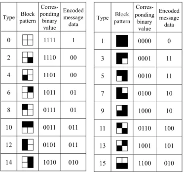
In order to embed a message into a binary image, every 2×2 image block is regarded as a pattern with a 4-bit binary value in which each bit of 0 corresponds to a black pixel and each 1 a white one. The proposed data embedding process is based on the use of a block pattern encoding table which maps each block pattern into a certain code with one, two, or three bits of the message data to be hidden. And data embedding is accomplished by changing the block bit values so that the corresponding code of the resulting block pattern become just some bits of the input message data to be embedded. A possible block pattern encoding table designed for use in this study is shown in Table 1. It is emphasized, by the way, that such a table is just one of the many possible tables which may be used for data hiding, and the proposed data embedding process will choose from them an optimal one for each specific input binary image, as described later.
Suppose that we want to embed one bit in a 2×2 block.
The number of possible patterns in a 2×2 block are 16. This number is much larger than the required number of 2 to represent the two different message bits ‘0’ and ‘1’ in a block, so we may use more than one block pattern to represent a single message bit (0 or 1), allowing the possibility of choosing among the block patterns an optimal one to replace the original block in the data embedding process and thus reducing more distortion in the resulting block. On the other hand, we wish to embed more data in a block, not just a bit as just mentioned; and for this we can use a block pattern to represent more than one bit, as is done in this study. In short, we want to achieve both minimum-cost bit replacement and maximum-volume data embedding.
As an illustration, we may use either the block pattern t1 = 10112 or the pattern t2 = 01112 to represent the two-bit message value s = 012. In this way, when we want to embed, for example, the message value s = 012 into a block B with value v = 10102, we have the two alternative block patterns t1
= 10112 and t2 = 01112 to choose to replace v =10102, instead of the conventional case of just one. And if we choose t1 = 10112 to replace v =10102, then less distortion of just a 1-bit error (occurring at the LSB position) will result. Contrastively, if only one block pattern, say, t2 = 01112 is available, then an error of 3 bits will result, causing more distortion in the resulting block. It is such an allowance of multiple choices for
block pattern replacement that achieves more distortion reduction in the proposed method. By the way, the previously- mentioned bit errors are used just for convenience of illustrating the advantage of multiple choices of replacing blocks; they in fact should be the replacement costs defined previously.
Table 1. A block pattern encoding table proposed in this study.
Type Block pattern
Corres- ponding binary
value
Encoded message data
0 1111 1
2 1110 00
4 1101 00
6 1011 01
8 0111 01
10 0011 011
12 0101 011
14 1010 010
Type Block pattern
Corres- ponding
binary value
Encoded message data
1 0000 0
3 0001 11
5 0010 11
7 0100 10
9 1000 10
11 0110 100
13 1001 101
15 1100 010
4.2 Data Embedding in Binary Images
The proposed data embedding process in binary bit-plane images consists of four major steps and includes two folds of distortion minimization, as described in the following.
(1) Computing bit costs for data embedding: We calculate the replacement cost value for each bit in the image according to the cost function defined in Section 3.
(2) Dividing the input image into blocks: We first divide each of bit planes bp0 through bp3 into non-overlap 2×2 blocks with every two neighboring blocks separated by a 1-pixel- wide line of pixels in between, as shown in Figure 2. And next, we select the first n “embeddable” blocks and concatenate them sequentially, where n is the length of the message data string to be embedded. A block is said to be embeddable in this study if the replacement cost value of any one bit of the block is not infinite.
(3) Using multiple block pattern encoding tables for first-fold distortion reduction: We generate all possible block pattern encoding tables and select an optimal one for use in the data embedding process, in the sense of introducing the least distortion. The reason is that a single block pattern encoding table will not be suitable for every input binary image; if an image is destroyed seriously after data embedding using a specific table like Table 1, it will be appropriate to use another table with other combinations of block patterns to encode the message data. Specifically, we exchange the encoded message data of certain types in Table 1 with those of the other types in the following way:
exchange the message data “0” with “1”;
exchange the message data “00” with “01”;
exchange the message data “10” with “11”;
exchange the message data “010” with “011”;
exchange the message data “100” with “101”;
exchange the message data “00” and “01” with “10”
and “11,” respectively;
exchange the message data “010” and “011” with
“100” and “101,” respectively.
By enumerating all possible cases in the above way, we can get the 128 distinct tables (numbered from 0 to 127) for selection to minimize the distortion.
(4) Applying search techniques for second-fold distortion reduction: Finally, we apply the dynamic programming technique to segment the input message data stream optimally into a series of codes and embed them in the input image, according to the cost function proposed previously. This reduces the resulting distortion further in a global sense.
Figure 2. Division of an input image into 2×2 blocks with separating lines(grids with bold boundaries are 2×2 blocks for data embedding)
4.3 Search for Optimal Solutions
The search cost proposed in this study for use in the adopted search technique is the total replacement cost in the resulting stego-image, computed from the summation of the replacement costs of all the bit changes in the replaced blocks.
In Table 1, block patterns can be used to encode one, two, or three message bits. Accordingly, when we embed a binary message value v, we have the three choices of embedding the first one, two, or three initial bits of v into a block. To determine how many bits should be embedded in a selected block, we may calculate first the cost for each of the three cases, and replace the selected block with the block pattern corresponding to the minimum cost. This method provides a quick way for data embedding; however, it is just a greedy search algorithm and in general does not yield an optimal solution.
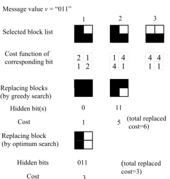
To see this, for example, suppose that the message value v of 0112 is to be embedded in three selected blocks with patterns B1 = 0100, B2 = 0100, and B3 = 1100 according to Table 1. And as illustrated in Figure 3, suppose also that the costs of replacing the four bits are computed to be 2, 1, 1, and 2 for B1; to be 1, 4, 4, and 1 for B2; and to be 4, 4, 1, and 1 for BB3. By the above-mentioned greedy search algorithm, we replace B1 = 0100 with the block pattern 0000 of type 1 to embed the initial bit 0 of v. The replacement cost for this block is 2×0 + 1×1 + 1×0 + 2×0 = 1 because a bit (the second bit) is flipped here with its corresponding cost being 1 and the other bits in the original block are not changed. This cost is a local minimum. Next, we replace B2 = 0100 with the block pattern 0001 of type 3 to embed the last two bits 112 of v, and the
replacement cost is 1×0 + 4×1 + 4×0 + 1×1 = 5. Therefore the total replacement cost for embedding v is 1 + 5 = 6.
Now, if we do not use the greedy search algorithm at the beginning, and replace instead B1 = 0100 by the block pattern 0101 of type 12 in Table 1 to embed the three bits 0112 of v directly, then the total replacement cost value will be reduced to be 2×0 + 1×0 + 1×1 + 2×1 = 3 which is smaller than the previously-computed total replacement cost of 6. This shows that there indeed exists at least one solution better than that found by the greedy search algorithm. Figure 3 illustrates the data embedding process for this example. This is also true for many other examples, as found by this study. And so the search of an optimal solution is meaningful, for which the proposed method is dynamic programming.
Figure 3. An example of proposed data embedding process.
4.4 Dynamic Programming for Data Embedding
In the proposed dynamic programming algorithm (abbreviated as DPA hereafter), edit distances are defined for cost minimization in the search. Assume that the input message data to be embedded are in the form of an n-bit string S1 with S1[i] denoting its ith bit. Also, let n 2×2 embeddable blocks be selected as a list in advance for data embedding and expressed as another string S2 with S2[i] denoting its ith block.
For convenience, let Sk[i~j] denote a substring of Sk with bits or blocks Sk[i] through Sk[j], where k =1, 2 and i, j = 1, 2, …, n.
Only one type of edit operation, namely, replacement, is used in the proposed DPA to specify the image block replacement operations involving S1 and S2 in the proposed data embedding process. The edit distance between S1 and S2
is defined, according to the previous discussions, as the minimum total replacement cost to transform S2 into S1 by editing operations according to a certain block pattern encoding table. Let C be an n×n cost matrix with its element C[j, i] denoting the minimum total replacement cost to transform a substring S2[j~n] of S2 into a substring S1[i~n] of S1. Then C[1, 1] is the minimum total replacement cost to transform S2[1~m] into S1[1~n] (i. e., to transform the substring of S2 into the entire string of S1), where 1 ≤ m ≤ n.
Also, let RC be a cost function with each of its element RC(j, i,
l) denoting the total replacement cost for replacing the jth block S2[j] of S2 with the block pattern which encodes the initial l bits of the substring S1[i~n] of S1 with l = 1, 2, or 3.
By the above definitions, the value C[j, i] is recursively just the minimum of all the possible values of RC(j, i, l) + C[j+1, i+l], where l = 1, 2 or 3. Then, according to dynamic programming, the minimum search cost and its corresponding solution may be computed by the following algorithm.
Algorithm 1. Computing minimum search cost for minimizing distortion by DPA.
Input: (1) an n-bit message data string S1; (2) a string S2 of n selected blocks; (3) a block pattern encoding table T;
(4) an n×n cost matrix C[j, i], for i, j = 1, 2, …, n; (5) an n×n type matrix I with its element I[j, i] used for recording the block pattern in T used for replacing S2[j]
in calculating C[j, i]; and (6) an n×n segmentation matrix N with its element N[j, i] used for recording the number of initial bits of S1[i~n] used in calculating C[j, i].
Message value v = “011”
Selected block list
Output: C[j, i], I[j, i], and N[j, i] for all i, j = 1, 2, …, n.
Steps:
1. Set all C[j, i] initially to be ∞ for all i, j = 1, 2, …, n.
2. Starting from i = n and j = n, for each pair of (j, i) with i, j = 1, 2, …, n, perform the following steps.
2.1 If C[j, i] is equal to ∞ , continue the next step (Step 2.2); else increment i and j to calculate the next C[j, i].
2.2 Take C[j, i] to be the minimum of the three replacement costs, RC(j, i, 1) + C[j+1, i+1], RC(j, i, 2) + C[j+1, i+2], and RC(j, i, 3) + C[j+1, i+3]; and record the corresponding number of the processed initial bits (1, 2, or 3) of S1[i~n] in N[j, i], and the corresponding type of the used block pattern of T in I[j, i].
In the above algorithm, the number of initial bits of S1[i~ n] and the used block pattern type in each recursive step are recorded in matrices N and I, respectively, which are used in the data embedding process, as described next.
Algorithm 2. Data embedding using block pattern encoding tables and DPA.
Input: (1) a grayscale image G; (2) a secret message data string S1 with n bits; (3) a control message data string Sc with m bits, including a table number Topt
(specifying the block pattern encoding table used) with seven bits, followed by a value Lopt (specifying the number of selected blocks used) with m-7 bits; and (4) 128 block pattern encoding tables.
Output: a stego-image S.
Steps:
1. Compute the cost of each bit of G as mentioned previously.
2. Get a list Bm of m 2×2 embeddable blocks sequentially from the bit planes bp0 through bp3 of G in order for embedding the m bits of Sc. Also, get a list Bn of n 2×2 embeddable blocks sequentially for the n bits of S1. Let Bm
and Bn also include the position information of each selected block.
3. For each block pattern encoding table T among the input 128 ones, with S1, Bn, and T as input, apply Algorithm 1 to calculate the cost matrix C[j, i], the type matrix I[j, i], and the segmentation matrix N[j, i] for all i, j = 1, 2, …, n.
4. Find the minimum Cmin of the 128 values of C[1, 1]
Replacing blocks (by greedy search)
Hidden bit(s) 0 11
Cost 1 5 (total replaced
cost=6)
optimum search) Replacing block (by
Hidden bits 011
Cost 3
(
total replaced cost=3)1 2 3
2 1 2 1
Cost function ofcorresponding bit
1 4
1
4 4 4
1
1
computed in the last step, and set Topt to be the table number of the corresponding block pattern encoding table used in computing Cmin.
5. Use the block pattern encoding table Topt, the type matrix Imin and the segmentation matrix Nmin corresponding to Cmin, and the position information of each block in Bn, to embed the string S1 into bp0 through bp3 of G to get the stego-image S .
6. Set the value Lopt to be the number of the blocks used for embedding S1 in the last step.
7. Using Sc (including Topt and Lopt), Bm, and T= 1 as input, apply Algorithm 1 to calculate the cost matrix C[j, i], the type matrix I[j, i], and the segmentation matrix N[j, i] for all i, j = 1, 2, …, m.
8. Use the block pattern encoding table Table 1, the type matrix I and the segmentation matrix N in the last step, and the position information of each block in Bm, to embed the substring Sc into bp0 through bp3 of G to get the final stego-image S.
5. PROPOSED DATA RECOVERY PROCESS The goal of data recovery is to extract the embedded message data from a stego-image, as described in the following.
Algorithm 3. Message data recovery
Input: a stego-image I' including a message bit stream S.
Output: the message bit stream S.
Steps:
1. Calculate the cost of every bit of G as mentioned previously.
2. Get m 2×2 embeddable blocks sequentially from bp0
through bp3 of I' as a list Lm.
3. For each 2×2 block P of Lm, compute the binary value v corresponding to the block pattern, and decode v by looking v up in the block pattern encoding table 1 to get the corresponding encoded message data bits as the data recovery result of P.
4. Concatenate the preface m data bits extracted in the last step into a sequence as a desired control message data Sc. 5. Get the preface 7 data bits of Sc as Topt, and the remaining
m-7 data bits of Sc as Lopt, which specify respectively (1) the optimal block pattern encoding table Topt used in data embedding; and (2) the number of 2×2 blocks of I' used in embedding S in the bp0 through bp3 of I'.
6. Also, get Lopt 2×2 selected blocks sequentially from bp0
through bp3 of I' as a list L.
7. For each 2×2 block P of L, compute the binary value v corresponding to the block pattern, and decode v by looking v up in the block pattern encoding table Topt to get the corresponding encoded message data bits as the data recovery result of P.
8. Concatenate all the data bits extracted in the last step into a sequence as the desired message S and exit.
For security consideration, we encrypt further the control message by a secret key before the data embedding process, and embed the result into bp0 through bp3 at bit positions randomly generated with a distinct secret key and a random number generator. The reverse process can be easily performed to get the original control message. The same method is also applied to the message data to get a higher degree of data protection.
6. EXPERIMENTAL RESULTS
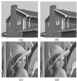
Figures 4 and 5 illustrate some experimental results of applying the proposed method. The bit streams of message data in Figures 4 and 5 were generated randomly. The stego- images “House” and “Lena” both of size 256×256 with high PSNR values of 56.88 dB and 68.44dB, respectively, obtained by embedding 16440 bits (about 2KB) message data using the DPA and the optimal block pattern encoding table among the 128 ones are shown Figures 4(b) and 4(d), respectively. The cover images are depicted in Figures 4(a) and 4(c) respectively for comparison. The results show that the proposed method can be applied to embed message data in grayscale images and obtain good-quality stego-images without noticeable artifacts in smooth image regions.
(a) (b)
(c) (d)
Figure 4. Some experimental results. (a) Cover image
“House.” (b) Stego-image of (a). (c) Cover image
“Lena.” (d) Stego-image of (c).
Figure 5 illustrates three grayscale stego-images “House”,
“Lena” and “Jet.” and results of data embedding. The three stego-images of size 128×128 were obtained by embedding 1000 bytes of message data using the proposed DPA and the optimal encoding table. The PSNR values are 46.90 dB, 49.33dB and 48.80 dB, respectively. In each row of the figure, from left to right are an original image, bp0, bp1, bp2, and bp3 of the original bit planes (copied from Figure 1), followed by the resulting stego-bit planes of bp0, bp1, bp2, and bp3, respectively. Compared with the cover images in Figure 1 and their four corresponding bit planes, it can be seen that the stego-images retain most significant textures.
Table 2 summarizes the statistical data of the stego-image
“Lena” using the DPA and the optimal encoding table, including the message data length, the PSNR value, the selected block pattern encoding table, the numbers of used blocks, the minimum replacement cost values, and the average of the numbers of embedded bits per block. The message data bit stream in Table 2 was generated randomly.
In more details, the result of Table 2 is transformed into Fig. 6. When the amount of the embedded data is smaller than 1000B, the PSNR values in Table 2 are all larger than 49dB.
And the differences in the stego-images are not noticeable.
Figure 5. Experimental results of three images. In each row, from left to right are the original image, bp0, bp1, bp2, and bp3 of original bit planes (copied from Fig. 1), followed by resulting stego-bit planes of bp0, bp1, bp2, and bp3.
Figure 6 also reveals that the relation between the PSNR value yielded by the proposed method and the embedded data amount is approximately linear. The PSNR value of the DPA decreases about 3.3225 dB when the embedded data size increases 200 bytes. Thus, the proposed DPA method can predict the PSNR value before the data embedding process starts according to the message data size. From Table 2, the PSNR value of the DPA can be estimated by a simple line fitting method to be PSNR = 62.5870 − (m − 1) × 3.3225 (dB), 1 ≤ m ≤ 5,
where m denotes the size of message data in the unit of 200 bytes for 128×128 grayscale images. Similar results can be observed for the other images. Moreover, the equation of the PSNR value can be extended and used for grayscale images of any sizes by applying the proposed DPA.For a grayscale image of size H×W, if the above value of m denotes the size of the message data in the unit of (200×H×W)/(128×128) bytes, then the resulting PSNR value still can be estimated using the above equation. Note that this merit of predictable PSNR values enables a user of the proposed method to determine in advance how large a cover image should be selected for a certain given amount of message data.
Furthermore, we may compute a distortion rate for each stego-image. This rate is computed in this study as the ratio of the number of bit flippings (changing bit 0 to 1 or 1 to 0 in data embedding) to the length of the message data. Most
existing vertical data hiding methods yield distortion rates of about 50% for grayscale images because of the characteristic of randomness in bit flippings. In most existing vertical data hiding methods, when 200-byte secret message data are embedded into a 128×128 grayscale image, these data will be divided into pieces of 4 bits and each piece is embedded into the bits b3b2b1b0 of a pixel. Then the average grayscale change of the pixel, measured in terms of the number of flipped bits, may be computed to be 1×50% + 2×50% + 4×50% + 8×50% = 7.5. Consequently, the corresponding mean square-error value MSE of the stego-image may be computed to be MSE = [(200×8)/4]×(7.5×7.5)]/(128×128) where (200×8)/4 is the number pixels required for embedding the 200-byte message data, 7.5×7.5 is the square error incurred at each pixel, and 128×128 is the image size. Finally, the PSNR value of the stego-image may be computed to be 10×log(2552/MSE) = 46.75 dB. Contrastively, in Table 2 the PSNR value of our method is a much larger value 62.48 dB, which means the proposed method is superior in distortion minimization.
In summary, the experimental results above show that for grayscale images, the proposed method takes effectively into consideration both the effect of the HVS and the preservation of local edges, and yields stego-images that are less distorted than those yielded by most existing data hiding methods.
Table 2. Statistics of stego-images yielded by DPA using optimal encoding table.
Stego - image
Message data length (bytes)
PSNR (dB)
Table number
No. of used blocks
Cost value PSNR VS embedded data
0 20 40 60 80
1 2 3 4 5 6 PSNR
unit: 200 bytes Figure 6. PSNR values of stego-image “Lena” using DPA.
Embedded bit number per block 200 62.48 8 779 1774 2.054 400 59.37 57 1636 3243 1.956 600 55.57 57 2297 5680 2.09 800 52.96 57 3101 8355 2.064 1000 49.33 8 3826 11699 2.091 Lena
(128
×128)
1200 46.74 57 4295 16248 2.235
7. CONCLUSIONS
Two novel methods for hiding message data into grayscale images with distortion reduction effects have been proposed, with one being the DPA and the other being the use of multiple block pattern encoding tables. A cost function has been proposed to estimate the weight of each bit in each pixel to be replaced according to an HVS model. A horizontal data hiding method in which message data are embedded in a sequence of bit planes has also been proposed to decrease possible distortions in stego-images. An optimal block pattern encoding table is chosen from 128 alternative ones for use in the proposed data embedding process to minimize the distortion in the stego-image. The proposed method minimizes further the distortion using dynamic programming based on the proposed cost function. The proposed method can embed up to three bits in a 2×2 image block. As a result, not only the textures in the cover image are reserved, but also the distortion of the stego-image can be effectively reduced in an optimal way. Especially, the proposed DPA can predict the PSNR value of a sego-image before the embedding process starts according to the size of the data to be embedded.
The space and time complexities of the proposed DPA are both of the order of n2. It may cost more time to embed a long secret code. But in certain applications there is no need of real-time processing, and optimality in data embedding volumes or minimization in image distortion is the main concern. In such cases, our method is good to use. On the other hand, if time is really concerned, then one can alternatively use the other proposed method, the greedy search algorithm, that takes only linear computation time and still minimize distortion in the stego-image in a suboptimal way.
On the other hand, at least two approaches may be adopted to make the proposed method more robust. First, we can embed multiple copies of the secret data in the embedding process so that attacks will not entirely destroy the secret information. If attacks do occur, then after the data are extracted by the proposed method, we may apply a voting scheme to recover the secret. The second approach is to try to place secret data in the more significant bits of the cover image, for example, in bp2 and bp3 in the proposed method, assuming that most attacks to BMP images are conducted to the LSBs. Because the information encoded in these bit-planes cannot be removed in most applications (otherwise, the image will be seriously distorted or destructed), hopefully this method will work in real applications.
The proposed method processes 2×2 blocks in the data embedding process. It may be extended to process larger-sized blocks because when the block size is larger, the number of the block patterns which can be selected to encode a certain message value becomes larger as well, resulting possibly in greater reduction of image distortion. Other future works may be directed to embed multiple message data in a grayscale image for protecting the intellectual property right and authenticating multimedia data, to define more general cost functions for other HVS models, and to design better encoding tables to reduce stego-image distortion further.
ACKNOWLEDGEMENT
This work was supported partially by the NSC Project Advanced Technologies and Applications for Next Generation Information Networks (II) with Project No. NSC93-2752-E- 009-006-PAE.
REFERENCES
[1] S. Katzenbeisser and F. A. P. Petitolas, Information Hiding Techniques for Steganography and Digital Watermarking, Artech House, Boston, U. S. A., 2000.
[2] L. M. Marvel, J. C. G. Boncelet, and C. T. Retter, “Spread spectrum image steganography,” IEEE Trans. on Image Processing, vol. 8, no. 8, pp. 1075-1083, Aug. 1999.
[3] M. Swanson, M. Kobayashi, and A. Tewfik, “Multimedia data-embedding and watermarking technologies,”
Proceedings of the IEEE, vol. 86, pp. 1064-1088, 1998.
[4] R. Z. Wang, C. F. Lin, and J. C. Lin, “Hiding data in Images by optimal moderately-significant-bit replacement,” IEEE Electronics Letters, vol. 36, no. 25, pp.
2069-2070, Dec. 2000.
[5] C. C. Chang, J. Y. Hsiao, and C. S. Chan, ”Finding optimal least-significant-bit substitution in image hiding by dynamic programming strategy,” Pattern Recognition, vol. 36, pp. 1583-1595, 2003.
[6] C. K. Chan and L. M. Cheng, "Improved hiding data in images by optimal moderately-significant-bit replacement," IEEE Electronics Letters, vol. 37, no. 16, pp.
1017-1018, Aug. 2001.
[7] C. K. Chan, and L. M. Cheng, "Hiding data in images by simple LSB substitution," Pattern Recognition, vol. 37, pp.
469-474, 2004.
[8] C. C. Thien and J. C. Lin, "A simple and high-hiding capacity method for hiding digit-by-digit data in images based on modulus function," Pattern Recognition, vol. 36, pp. 2875-2881, 2003.
[9] Y. K. Lee and L. H. Chen, “High capacity Image steganographic model,” IEE Proceedings on Vision, Image Signal Process, vol. 147 no. 3, June 2000.
[10] S. H. Liu, T. H. Chen, H. X. Yao, and W. Gao, “A variable depth LSB data hiding technique in images,”
Proceedings of 3rd International Conference on Machine Learning and Cybernetics, pp. 3990-3994, Shanghai, P. R. China, Aug. 2004.
[11] D. C. Wu and W. H. Tsai, “Spatial-domain image hiding using an image differencing,” IEE Proceedings-Vision, Image, and Signal Processing, vol. 147, no. 1, pp. 29-37, 2000.
[12] W. N. Lie, and L. C. Chang, “Date hiding in images with adaptive numbers of least significant bits based on the human visual system,” Proceedings of IEEE International Conference on Image Processing, Taipei, Taiwan, vol. 1, pp. 286-290, Oct. 1999.
[13] I. S. Lee and W. H. Tsai, “A Dynamic-Programming Approach to Data Hiding in Binary Images Using Block Patterns with Distortion Minimizing Capability,”
Proceedings of National Computer Symposium NCS'2003, Taichung, Taiwan, Dec. 2003.
[14] A. K. Jain, Fundamentals of digital image Processing, Prentice-Hall, Singapore, 1989.