Using an Electro-spraying Microfluidic Chip to Produce Uniform
Emulsions under a Direct-Current Electric Field
Chia-Hsien Yeh\ Meng-Hsuan Lee1, and Yu-Cheng Lin1• 2• *
1
Department of Engineering Science, National Cheng Kung University, Tainan, Taiwan
2
Center for Micro/NanoTechnology, National Cheng Kung University, Taiwan
*Corresponding author: Yu-Cheng Lin
National Cheng Kung University, Department of Engineering Science,
1 University Road, Tainan 701, Taiwan, R.O.C.
E-mail: [email protected]
Tel: +886-6-276-2395
Fax: +886-6-276-2329
Source: Microfluidics and Nanofluidics, Vol.12, No.1-4, pp.475-484 Date of Publication: 2012-01
ISSN: 1613-4982 Publisher: Springer Verlag DOI: 10.1007/s10404-011-0889-z
Abstract
An electro-spraying microfluidic chip was integrated with a parallel electrode and
flow-focusing device to successfully generate uniform emulsions with an electric field. This
approach utilizes a high electric field driven by a direct-current voltage to form a stable
Taylor cone in the flow-focusing position. The Taylor cone can then generate stable and
uniform emulsions that are less than 5 f.!m in diameter. The emulsion size is controlled by the
surfactant concentration, the ratio of the water and oil phase flow rates and the strength of the
electric field. When the strength of the electric field increases at a high surfactant
concentration and low ratio of flow rates, the Taylor angle decreases, which causes the
emulsion size to decrease. In this study, the water emulsion diameter ranged from 1 f.!m to 98
f.!m, and the poly(lactic-co-glycolic acid) (PLGA) emulsion size ranged from 7 f.!m to 70 f.!m.
The microfluidic chip developed in this work has the advantages of actively controlling the
emulsion size and generating uniform emulsions (the relative standard deviation was less
than 10%) and represents a new emulsion generation process.
Keywords: electro-spraying microfluidic chip, emulsions, parallel electrode, electric field,
1. Introduction
Microfluidic technology that uses flow-focusing shapes has a wide range of applications
that can be used to generate water-in-oil emulsions and oil-in-water emulsions in liquid-liquid
systems [1-3]. This microfluidic technology provides a highly controllable emulsion size, and
the emulsions thus produced can be applied for microreaction synthesis [4], chemical reaction
[5], protein crystallization [6], and the formation of colloidal particles with different shapes
[7, 8]. Various flow-focusing shapes are used to produce emulsions, whose sizes are
controlled by the flow rates [9-17], although the smallest emulsion size is limited by the
microfluidic geometry, the dimensions of the microchannel, and the material properties of the
fluids. The electro-spray approach has the potential to overcome these limitations and is able
to generate emulsions in a high electric field [18]. In this method, an electro-spray is
generated by an electric force applied to the surface of a liquid, and this can be used to
produce the water emulsions as small as 1 f.!m in diameter. In previous studies of
electro-spray methods, emulsions have been generated with one liquid in air in an electric
field [19-21]. Mutoh et al. (1979) reported the convergence of various viscous liquids with
different conductivities [20]. Hayati et al. (1986) studied the electro-spray mechanism to
form a stable jet under an electric field [21]. Thus, previous studies showed that the dispersed
phase solution should have slightly conductivity to form a Taylor cone. Sato et al. (1997)
presented a method to achieve droplet generation in water and explained the
numerical modeling to simulate dynamic Taylor cone formation on liquid metal surfaces [23].
The hydrodynamic evolution of the surface of a liquid metal in the presence of an electric
field has been investigated using both analytical and numerical techniques [24]. The
electro-hydrodynamic (EHD) atomization process was simulated with a commercial
Computational Fluid Dynamics (CFD) code [25]. Ganan-Calvo et al. combined the
electro-spray and flow-focusing processes to develop an ultra-fine liquid atomization
procedure [26, 27]. Kim et al. (2007) proposed an emulsification method that uses an electric
field to generate water droplets in a flow-focusing microfluidic device [28]. In our study, the
electro-spraying method was also carried out in a microfluidic device that included a
flow-focusing shape based on the concept described in ref. [28]. Many biomaterials have
been used to form uniform emulsions for the controlled release of drugs, including alginate [9,
10], chitosan [11], poly(lactic-co-glycolic acid) (PLGA) [12, 13], and other substances [14],
due to their excellent properties, such as biocompatibility, biodegradability, and non-toxicity.
PLGA is one of the most widely used biomaterials for drug delivery and therapeutic
encapsulation and is a synthetic polymer that includes glycolic and lactic acid. PLGA is
particularly known for its biocompatibility and biodegradability because it breaks down into
harmless acid monomers in the human body. However, biomaterials have not been applied in
electro-spray micro-fluidic devices to generate smaller emulsions. Therefore, PLGA was used
to form emulsions in this study.
electrode and flow-focusing device. A high electric field driven by a direct-current voltage
and an indium-tin-oxide (ITO) parallel electrode formed a stable Taylor cone in the
flow-focusing position and generated uniform emulsions. There are many factors that can
influence emulsion size, such as surfactant concentration (Span 80), the ratio of the water and
oil phase flow rates, and voltage (electric field). In this study, the water emulsion diameter
ranged from 1 J.lm to 98 J.lm. The microfluidic chip developed in this work was applied to
generate PLGA emulsions, whose sizes ranged from 7 J.lm to 70 J.lm in diameter.
2. Materials and Methods 2.1 The Experimental Principle
In this study, an electro-spraying microfluidic chip was integrated with a hydrodynamic
flow-focusing function and parallel electrodes to generate the electro-spray phenomenon
under microfluidic conditions, as shown in Fig. l(a). In previous research, the emulsion size
was controlled by the orifice geometry, the fluid material properties (viscosity or surfactant),
and the ratio of the sample and oil phase flow rates. According to ref. [28], an electric field
can also be used to control emulsion size in an electro-spraying microfluidic chip. When
parallel electrodes were used to generate an electric field in the dispersed phase, the front
surface of the disperse phase which was formed to be the hydrodynamic-focusing shape by
the continuous phase was charged. When the strength of the electric field increased, the
force. Because the attracting force generated by the higher electric field was larger than the
surface tension of the water-oil interface, a Taylor cone was generated at the tip of the
dispersed phase. Therefore, the electro-spray condition (Taylor cone) was generated in the
developed microfluidic chip with a high electric field, and this can be used to produce
emulsions with smaller diameters.
2.2 Design and Fabrication of the Electro-spraying Microfluidic Chip
An electro-spraying microfluidic chip was designed using AutoCAD® 2010 software
and included parallel electrodes and a flow- focusing microchannel. The dimensions of the
microfluidic chip are 3 x 3 x 6 mm, and the gap between the parallel electrodes is 4 mm. The
cross-junction angle of the flow-focusing microchannel is 60°, and the width is 1 00 J.lm, as
shown in Fig. 1(a).
The electro-spraying microfluidic chip consists of two components: the flow-focusing
microchannel and the parallel electrodes. The flow-focusing microchannel was fabricated
from poly( dimethylsiloxane) (PDMS) with micro-electro-mechanical systems (MEMS)
technology [29]. First, a THB-151 N microstructure mold was fabricated on a silicon wafer
using MEMS technology, including spin coating, exposure and developing. After creating the
THB-151N mold, replica mold technology was used to fabricate the PDMS flow-focusing
microchannel. The PDMS liquid was poured into the THB-151N mold, and the PDMS chip
were fabricated on an ITO glass slide with standard MEMS technology [30].
Microfabrication processes, such as spin coating, exposure, developing, and wet etching,
were used to fabricate thin-film micro-electrodes. After the electrode pattern was transferred
onto the ITO glass slide, the parallel electrodes were formed by chemical wet etching. Finally,
an oxygen plasma machine (In-line plasma cleaner, NEWST-2002IL, Taiwan) was used to
change the surface functional groups ofthe PDMS microchannel and the ITO glass substrate
from CH3 groups to OH groups. The PDMS microchannel was tightly bonded to the ITO
glass substrate [31]. The parameters for oxygen plasma treatment were 75 mTorr of vacuum
pressure and 70 W of RF power applied for 30 sec. The flow-focusing microchannel thus
obtained had a depth of 70 11m, as measured by an Alpha-step profilometer (AS500, KLA
Tencor, Japan).
2.3 The Experimental Procedure
In this study, the electro-spraying microfluidic chip that was developed could control the
emulsion size by adjusting the direct-current electric field under a fixed ratio of the dispersed
and continuous phase flow rates. By increasing the strength of the electric field, a Taylor cone
was produced at the cross-junction position, which caused the emulsion size to become
smaller. First, distilled water (D.I. water) was injected into the central microchannel as the
dispersed phase, while mineral oil, which was used as the continuous phase, flowed through
dispersed phase and the continuous phase were delivered to the cross-junction position using
hydrodynamic pressure. The dispersed phase solution should be slightly conducting to form a
Taylor cone; however, because the dispersed phase solution had high conductivity, there was
no potential difference in the solution to form the Taylor cone [21]. The conductivity of the
D.l. water was 2.4 JlS/cm and that of the 1% PLGA solution (w/w), which was mixed with a
dimethyl sulfoxide (DMSO) solution, was 3.4 JlS/cm. The conductivity of the mineral oil
with Span 80 (3%) added as a surfactant was 0.16 JlS/cm. The properties of all of the fluids
are shown in Table 1. The flow-focusing microchannel was used to generate the continuous
emulsions at the cross-junction position by the oil phases. The experimental images were
obtained using an optical microscope (BX60, Olympus, Japan) and a digital camera (DP70,
Olympus, Japan). The emulsion size was measured with Adobe Photoshop software. The
diameters of 10 emulsions were measured and an average size and standard deviation were
calculated. To generate smaller emulsion sizes by electro-spraying, an electric field (voltage)
was added in the flow-focusing microchannel. The source and ground electrodes of a
high-power supply machine were connected to the ITO electrodes, which made contact with
the microchannels. The applied potential difference under the fixed distance ( 4 mm) between
the electrodes was used to determine the strength of the electric field in this study. The
continuous phase flow rate was fixed to 400 J.1Lihr, and the flow rate ratio was adjusted by changing the dispersed phase flow rate. The D.l. water emulsion size was controlled by the
10/400, and 5/400), the Span 80 concentration (0, 3, 5, and 7%), and the voltage (0, 1000,
2000, 3000, 4000, 5000, and 6000 V). Finally, the developed microfluidic chip was used to
produce PLGA microparticles. A 1% PLGA solution (w/w) prepared by mixing with a DMSO
solution; this solution and mineral oil were injected into the electro-spraying microfluidic
chip as the dispersed and continuous phases, respectively. The PLGA emulsion size was
controlled by the ratio (Qs/Qo) of the dispersed phase and the continuous phase flow rates
(80/400, 40/400, 20/400, and 10/400), the Span 80 concentration (0, 3, and 5%), and the
voltage (0, 1000, 2000, 3000, and 4000V). After the PLGA emulsions were generated by the
microfluidic chip and transported to the reservoir via a Teflon tube, the solvent (DMSO) was
evaporated, and the PLGA microparticles were collected, as shown in Fig. 1 (b)-( c).
3. Results and Discussion
3.1 The Influences on the Water in Oil (W/0) Emulsion Size
The various Span 80 concentrations were mixed with mineral oil to modify the surface
tension between the water and oil phases. When the Span 80 concentration was 0%, the water
emulsion size was decreased at a lower flow rate ratio (Qs/Qo) under no voltage. After the
voltage was increased from 2000 V to 5000 V, the emulsion generation was unstable, and the
water emulsion size was not uniform. Moreover, the fluid tip of the dispersed phase in the
cross-junction position did not form a Taylor cone. When the Span 80 concentration was 3%
that of the experiment with 0% Span 80 under the same conditions (the same flow rate ratio
and voltage). When the Qs/Qo was smaller than 20/400 and the voltage was increased from
4000 V to 6000 V, the fluid tip of the dispersed phase in the cross-junction position formed a
Taylor cone, and the smallest water emulsion size was generated due to the electro-spraying
conditions. When the Span 80 concentration was increased to 5% (w/w), the water emulsion
size was smaller than that observed in the experiments with 0% and 3% Span 80 under the
same conditions. When the flow rate ratio was decreased or the voltage was increased, the
emulsion size decreased, as shown in Fig. 2(a). At a voltage of 6000 V, a Taylor cone was
formed at all flow rate ratios, and the smallest emulsion size, 1 11m in diameter, was produced
using the electro-spraying conditions (Fig. 2(b) ). Therefore, when the surface tension
between the dispersed phase and oil phase was reduced, the generation of water emulsions
was stable, and the water emulsion size was smaller under the same parameters. To examine
the effect of the flow rate ratio on Taylor cone generation, when the flow rate ratio was
decreased from 80/400 to 5/400 at 6000 V, the angle of the Taylor cone was decreased from
32.2° to 18°, as shown in Fig. 3. The results show that the flow rate ratio influenced the
Taylor cone generation. When the dispersed phase was strongly compressed by the
continuous phase under the high Span 80 concentration, a Taylor cone was formed to easily
generate smaller emulsions. Thus, under the fixed voltage of 4000 V, a Taylor cone was only
generated at a flow rate ratio of 5/400, as shown in Fig. 2.
flow rate ratios, the water emulsion diameter ranged from 33 11m to 98 11m at a 0%
concentration of Span 80. When the voltage exceeded 2000 V, the flow-focusing shape in the
cross-junction position was unstable and the emulsion size was not uniform. Although the
electric field influenced emulsion generation, there was no electro-spraying condition to
generate smaller emulsions. With a 3% Span 80 concentration, the emulsion size was
significantly influenced by the driving voltage at low flow rate ratios (20/400, 10/400, and
5/400), as shown in Fig. 4(a). The W/0 emulsion size was less than 5 11m in diameter at 5000
V, and the emulsion size was 1 11m at Qs/Qo=5/400 and 6000 V. Finally, at a 5% Span 80 concentration, when the driving voltage was increased to 6000 V, the W /0 emulsion size was
less than 5 11m at all flow rate ratios, as shown in Fig. 4(b ). In the experiments, the generation
of regular water emulsions was controlled by parameters such as the flow rate ratio of the
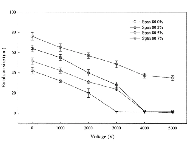
water and oil solutions, Span 80 concentration, and driving voltage, as shown in Table 2. The
lowest driving voltages used to generate the stable electro-spraying condition at Span 80
concentrations of 3%, 5%, and 7% were 4000 V, 4000 V, and 3000 V, respectively, at a flow
rate ratio of 5/400, as shown in Fig. 5. The contact angles of the different Span 80
concentrations (3%, 5%, and 7%) were 24.2°, 23°, and 23.8°, respectively. Therefore, when
the Span 80 concentration is high, a low driving voltage can be used to generate the
electro-spraying condition.
In electro-spray theory, when the strength of the electric field increases, the charge on
Because the attracting force generated by the higher electric field is larger than the surface
tension of the water-oil interface, a Taylor cone is generated at the tip of the dispersed phase.
Then the tip of the Taylor cone continuously releases charged micro-emulsions; this
represents the electro-spraying condition. The electric field of the Taylor cone surface is
determined using equation 1, where E is the electric field strength, V is the driving voltage, R
is the curvature radius of the Taylor cone, and d is the distance between the electrodes.
E=_l:J___
Rln4dR
(1)
According to equation 1, when the curvature radius is small or, alternatively, when the Taylor
cone is sharp, the electric field is strong. In ref. [32], Reneker et al. reported that in their
experiments when the Taylor cone was stably generated in air, the potential difference at the
Taylor cone surface was zero. According the theoretical calculation described by equation 2,
the angle of the Taylor cone (a) was 49.3° in air:
1 1 dn
<I>= <Po+ (TR)zP1(Cos(l80-a)), P(x) = - n - - n [(x2 - l)n]
2 2 n! dx (2)
where <I> is the surface potential of the Taylor cone, T is the surface tension, R is the curvature
radius of the Taylor cone, and a is the angle of the Taylor cone.
In our study, a Taylor cone was generated at the water-oil interface (Span 80 was added
to the oil phase to modify the surface tension), which was compressed by the oil phases. Thus,
the angle of the Taylor cone was smaller than 49.3° in the electro-spraying microfluidic chip.
Span 80 was used to adjust the surface tension between the water phase and the oil phase:
observed that when the Span 80 concentration was increased from 0% to 7% under the fixed
parameters, the curvature radius and the angle of the Taylor cone were reduced. According to
equation 1, when the curvature radius is reduced by increasing the surface tension under a
fixed driving voltage, the front charge density of the Taylor cone is increased, which
produces smaller emulsions. To examine the effect of the flow rate ratio on Taylor cone
generation, when the flow rate ratio was decreased from 80/400 to 10/400 at 6000 V, the
angle ofthe Taylor cone was reduced from 32.2° to 18°, as shown in Fig. 3. The results show
that the flow rate ratio influenced the generation of a Taylor cone. Therefore, our
experimental results match those predicted by electro-spray theory.
3.2 PLGA Emulsion Generation
Based on the results of our experiments, the electro-spraying microfluidic chip proposed
in this work can be used to generate small emulsions less than 5 j..lm in size by controlling the
driving voltage and flow rate ratio. For the generation of PLGA emulsions, the pregel
solution (1% (w/w) PLGA mixed with DMSO) and mineral oil were the dispersed and
continuous phase, respectively. In the following experiments, the generation of regular PLGA
emulsions was controlled by parameters such as the flow rate ratio of the pregel and oil
solutions, Span 80 concentration, and driving voltage.
At a 0% Span 80 concentration, when the driving voltage was increased to 3000 V, the
size to be non-uniform. The PLGA emulsion size ranged from 40 !J.m to 70 !J.m, which was
not obviously influenced by the driving voltage to generate a smaller emulsion size. At a 3%
Span 80 concentration, the PLGA emulsion size was smaller than the size of the emulsions
generated at a 0% Span 80 concentration under the same conditions because the surface
tension between the PLGA phase and oil phase was reduced. When the driving voltage was
increased from 0 V to 4000 V, the PLGA emulsion size decreased from 42 !J.m to 14 !J.m at a
low flow rate ratio (Qs/Q0=20/400 and 10/400). However, a PLGAjet appeared at 4000 Vat
a high flow rate ratio (Qs/Qo= 80/400 and 40/400), as shown in Fig. 6. At high flow rate
ratios (Qs/Qo= 80/400 and 40/400), because the viscosity of the PLGA/DMSO (35.3 mPa.s)
was greater than that of the D.l. water (1.6 mPa.s), the PLGA phase was stretched to form a
jet rather than form emulsions by the high voltage ( 4000 V). At low flow rate ratios,
(Qs/Qo=20/400 and 1 0/400) PLGA emulsions were generated at 4000 V, but this was not the
case at higher flow rate ratios (Qs/Qo= 80/400 and 40/400). Lower flow rate ratios provided a
higher flow-focusing pressure, which compressed the PLGA phase to form a sharper Taylor
cone at each voltage; therefore, the smaller PLGA emulsions were easily generated at the
higher electric field ( 4000 V) and lower flow rate ratio (1 0/400). Moreover, the
electro-spraying condition did not affect the size of the PLGA emulsions or that of the water
emulsions, but the generation of a Taylor cone was affected by the driving voltage, which
caused the PLGA emulsion size to decrease. When the flow rate ratio (Qs/Qo) was high, the
However, the PLGA emulsion size did markedly decrease when increasing the driving
voltage at a lower flow rate ratio (20/400 and 1 0/400), as shown in Fig. 7(a). The PLGA
emulsion size ranged from 13 !liD to 51 11m in diameter. When the Span 80 concentration was
increased to 5%, the PLGA emulsion sizes were smaller than those generated at 0% and 3%
Span 80 under the same conditions. By increasing the driving voltage, the smallest PLGA
emulsion was 7 !liD in diameter at a flow rate ratio of 10/400 and voltage of 3000 V, as shown
in Fig. 7(b ). We also found that a PLGA jet appeared at a high flow rate ratio when the
voltage exceeded 2000 V. All of the parameters that influenced the size of the water and
PLGA emulsions are shown in Table 2. The bracketed value is defined as the ratio d/d0,
where d is the emulsion diameter and do is the reference value for the emulsion size. The
reference value used was the maximum emulsion size, which occurred at a Span 80
concentration of 0%, a driving voltage of 0 V, and a flow rate ratio of 80/400. At a Span 80
concentration of 5%, the water emulsion size ranged from 80 )..LID to 62 )..LID, and the PLGA
emulsion size ranged from 41 11m to 13 )..LID at no driving voltage when the flow rate ratio was
reduced from 80/400 to 10/400. However, to produce emulsions that were smaller than 10 !liD
in diameter using this device, the electric field strength was increased. For example, at a Span
80 concentration of 5%, the PLGA emulsion size ranged from 7 )..LID to 11 11m at a flow rate
ratio of 10/400 when the driving voltage was increased from 1000 V to 3000 V. Therefore,
the electric field is the parameter to control to reduce the emulsion size. Finally, PLGA
(DMSO) was evaporated, PLGA microparticles were generated, and the emulsion diameter
observed by SEM (TM-1000, Hitachi, Japan) was 2.6 J..tm, as shown in Fig. 8. In the
theoretical calculation, the PLGA microparticle size was 2.9 J..tm in diameter. The deviation of
the PLGA microparticles was 0.3 J..tm, and the percentage error was 10%. We believe that
when the DMSO solution fully evaporated from the reservoir solution, a very small volume
ofthe PLGA was carried out by the DMSO solution, which caused the experimental error.
4. Conclusions
In this work, an electro-spraying microfluidic chip successfully generated a uniform
W/0 emulsion measuring less than 5 J..tm in diameter with a high driving voltage (electric
field); this device was then used to generate PLGA microparticles. The emulsion size was
controlled by the flow rate ratio, the Span 80 concentration, and the driving voltage. By
increasing the driving voltage and Span 80 concentration to form a Taylor cone in the
flow-focusing position, the water emulsion size ranged from 1 J..lm to 98 J..tm in diameter, and
the PLGA emulsion size ranged from 7 J..tm to 70 J..tm. Therefore, the microfluidic chip
developed in this work has the advantages of being able to actively control the emulsion size
and generate uniform emulsions (the relative standard deviation was less than 10%) and
Acknowledgements
The authors would like to thank the Center for Micro/NanoTechnology, National Cheng
Kung University, Tainan, Taiwan, R.O.C., for access to equipment and technical support. This
research was partially supported by the Southern Taiwan Science Park Administration
(STSPA), Taiwan, R.O.C. under contract no. EZ-10-09-44-98, and the National Science
Council under grants 97-2221-E-006-222-MY3. This paper is also partially supported by
"Aim for the Top University Plan" of the National Chiao Tung University and Ministry of
References
[1] S.L. Anna, N. Bontoux, and H.A. Stone, "Formation of dispersions using flow focusing
in microchannels," Applied physics letters, 82, 364-366, 2003.
[2] T. Nisisako, T. Torii, and T. Higuchi, "Droplet formation in a microchannel network,"
Lab on a chip, 2, 24-26, 2002.
[3] M. Joanicot and A. Ajdari, "Droplet control for microfluidics," Science, 309, 887-888,
2005.
[4] H. Zhang and A.I. Cooper, "Synthesis and applications of emulsion-templated porous
materials," Soft matter, 1, 107-113, 2005.
[5] T. Taniguchi, T. Torii, and T. Higuchi, "Chemical reactions in microdroplets by
electrostatic manipulation of droplets in liquid media," Lab on a chip, 2, 19-23, 2002.
[6] B.T.C. Lau, C.A. Baitz, X.P. Dong, and C.L. Hansen, "A complete microfluidic screening
platform for rational protein crystallization," Journal of the American Chemical Society,
129, 454-455, 2007.
[7] Z. Nie, S. Xu, M. Seo, P.C. Lewis, and E. Kumacheva, "Polymer particles with various
shapes and morphologies produced in continuous microfluidic reactors," Journal of the
American Chemical Society, 127, 8058-8063, 2005.
[8] S.M. Yang, S.H. Kim, J.M. Lim, and G.R. Yi, "Synthesis and assembly of structured
colloidal particles," Journal of Materials Chemistry, 18, 2177-2190, 2008.
microspheres using microfluidic channels as a carrier of gold nanoparticles," Lab on a
chip, 6, 954-957, 2006.
[10] C.H. Yeh, Q. Zhao, S.J. Lee, and Y.C. Lin, "Using aT-junction microfluidic chip for
monodisperse calcium alginate microparticles and encapsulation of nanoparticles,"
Sensors and Actuators A-Physical, 151,231-236.2009.
[11] C.H. Yang, K.S. Huang, P.W. Lin, and Y.C. Lin, "Using a cross-flow microfluidic chip
and external crosslinking reaction for monodisperse TPP-chitosan microparticles,"
Sensors and Actuators B-Chemical, 124, 510-516,2007.
[12] L.H. Hung, S.Y. Teh, J. Jester, and A.P. Lee, "PLGA micro/nanosphere synthesis by
droplet microfluidic solvent evaporation and extraction approaches," Lab on a chip, 10,
1820-1825,2010.
[13] Q. Xu, M. Hashimoto, T.T. Dang, T. Hoare, D.S. Kohane, G.M. Whitesides, R. Langer,
and D.G. Anderson!, "Preparation of monodisperse biodegradable polymer microparticles
using a microfluidic flow-focusing device for controlled drug delivery," Small, 5,
1575-1581, 2009.
[14] C.H. Yeh and Y.C. Lin, "Using a cross-flow microfluidic chip for monodisperse
UV-photopolymerized microparticles," Microfluidics and Nanofluidics, 6, 277-283,
2009.
[15] C.H. Wu, W.S. Hsu, K.W. Fan, Y.L. Lin, and Y.C. Lin, "Optimization of an optical disc
experiment," Journal of Micro/Nanolithography, MEMS, and MOEMS, 9, 031011-1-9,
2010.
[16] A. M. Ganan-Calvo, "Generation of Steady Liquid Microthreads and Micron-Sized
Monodisperse Sprays in Gas Streams," Physical review letter, 80, 285-288, 1998.
[17] A. M. Ganan-Calvo and J. M. Gordillo, "Perfectly Monodisperse Microbubbling by
Capillary Flow Focusing," Physical review letter, 87, 274501-1-4, 2001.
[18] S.G. Taylor, "Disintegration of Water Droplets in an Electric Field," Proceedings of
the Royal Society of London. Series A, Mathematical and Physical Sciences, 280,
383-397, 1964.
[19] B. Vonnegut and R. L. Neubauer, "Production of monodisperse liquid particles by
electrical atomization," Journal of Colloid Science, 7, 616-622, 1952.
[20] M. Mutoh, S. Kaieda, and K. Kamimura, "Convergence and disintegration of liquid jets
induced by an electrostatic field," Journal of Applied Physics, 50, 3174-3179, 1979.
[21] I. Hayati, A. I. Bailey, and T. F. Tadros, "Mechanism of stable jet formation m
electrohydrodynamic atomization," Nature, 319, 41-13, 1986.
[22] M. Sato, T. Hatori, and M. Saito, "Experimental investigation of droplet formation
mechanisms by electrostatic dispersion in a liquid-liquid system," IEEE Transactions on
Industry Applications, 33, 1527-1534, 1997.
[23] V.G. Suvorov and E.A. Litcinov, "Dynamic Taylor cone formation on liquid metal
2000.
[24] V.G. Suvorov, N.M. Zubarev, "Formation of the Taylor cone on the surface of liquid
metal in the presence of an electric field," Journal of Physics D: Applied Physics, 37,
289-297, 2004.
[25] 0. Lastow, and W. Balachandran, "Numerical simulation of electrohydrodynamic (EHD)
atomization," Journal ofElectrostatics, 64, 850-859, 2006.
[26] A.M. Ganan-Calvo, J.M. Lopez-Herrera, and P. Riesco-Chueca, "The combination of
electrospray and flow focusing", Journal of Fluid Mechanics, 566, 421-445, 2006.
[27] A.M. Ganan-Calvo, "Electro-flow focusing: The high-conductivity low-viscosity limit,"
Physical review letters, 98, 134503-1-4, 2007.
[28] H. Kim, D. Luo, D. link, D.A. Weitz, M. Marquez, and Z. Cheng, "Controlled
production of emulsion drops using an electric field in a flow-focusing microfluidic
device," Applied physics letters, 91, 133106-1-3,2007.
[29] V. S. Rao, V.Kripesh, S.W. Yoon, and A.A.O. Tay, "A thick photoresist process for
advanced wafer level packaging applications using JSR THB-151 N negative tone UV
Photoresist," J. Micromech. Microeng., 16, 1841-1846, 2006.
[30] L.J. Yang, J.M. Wang, and Y.L. Huang, "The micro wn drag pump usmg
indium-tin-oxide (ITO) electrodes to resist aging," Sensors and Actuators A-Physical, 111,
118-122,2004.
Science and Technology, 8, 1063-1075, 1994 ..
[32] A.L. Yarin, S.K. Koombhongse, D.H. Reneker, "Taylor cone and jetting from liquid
droplets in electrospinning of nanofibers," Journal of applied physics, 90, 4836-4846,
Table Captions
Table 1 The properties of the liquids.
Table 2 The experimental parameters (driving voltage, surfactant concentration, and flow rate
Figure Captions
Figure 1 (a) Schematic of the electro-spray microfluidic chip. The microchannel was 100
!Jill in width, and the parallel ITO electrode gap size was 4 mm. (b) Schematic of
the PLGA emulsions collected in the reservoir by the silicone tube. (c) Schematic
ofthe solvent solution (DMSO) evaporation.
Figure 2 (a) The water emulsions generated by the various flow rate ratios and driving
voltages at a 5% Span 80 concentration. (b) The water emulsions generated at a
flow rate ratio of 80 and a driving voltage of 6000 V.
Figure 3 The angles of the Taylor cones generated by the different flow rate ratios at a 5%
Span 80 concentration and a 6000-V driving voltage: (a) 0/0, (b) 80/400, (c) 40/400,
and (d) 10/400.
Figure 4 (a) The relationship between the water emulsion size and voltage at different flow
rate ratios at a 3% Span 80 concentration. (b) The relationship between the water
emulsion size and voltage at different flow rate ratios and a 5% Span 80
concentration.
Figure 5 The relationship between the emulsion size and voltage at different Span 80
concentrations and a flow rate ratio of 5/400.
Figure 6 The PLGA emulsions generated by the various flow rate ratios and driving voltages
at a 3% Span 80 concentration.
rate ratios and a 3% Span 80 concentration. (b) The relationship between the PLGA
emulsion s1ze and voltage at different flow rate ratios and a 5% Span 80
concentration.
Figure 8 After the DMSO solution was evaporated, PLGA microparticles were observed by
Tables
Table 1
Fluid property Density (g/mL) Viscosity (m.Pas) Conductivity (J.Ls/cm)
0.1. water 1.00 0.92 2.40
PLGA(1%) 1.30 2.52 3.40
Mineral oil (Span 80 ofO%) 0.80 11.00 0.16
Mineral oil (Span 80 of3%) 0.80 11.47 0.16
Mineral oil (Span 80 of 5%) 0.80 11.80 0.16
Mineral oil (Span 80 of7%) 0.80 12.40 0.16
Table 2
Wateremulsion (J.lm) PLGAemulsion (J.lm) Flow rate ratio Flow rate ratio
Span 80 cone. Driving voltage (V) 80/400 40/400 20/400 10/400 5/400 80/400 40/400 20/400 !0/400 0 98(1) 90 (0.92) 84 (0.86) 80 (0.82) 76(0.78) 70 (I) 65 (0.93) 61 (0.87) 57(081) 1000 92 (0.93) 86 (0.88) 69(0.7) 69(0.7) 51 (0.52) 63 (0.9) 61(0.87) 57 (0.81) 56(0.8) 2000 0% 80 (0.82) 60(0.61) 58 (0.59) 38 (0.39) 37 (0.38) 62(0.88) 60 (0.86) 57 (0.81) 55 (0.79) 3000 68 (0.69) 53 (0.54) 43 (0.44) 37 (0.37) 35 (0 36) 60 (0.86) 59 (0.84) 56 (0.8) 54 (0.77) 4000 65 (0.66) 50 (0.51) 41 (0.42) 35(0.35) 33 (0.34) 59 (0.84) 59 (0.84) 53 (0.76) 52 (0.74) 5000 58 (0.82) 58 (0.83) 52 (0.74) 44 (0.63) 0 88 (0.9) 75 (0.77) 73 (0.74) 68 (0.69) 64 (0.65) 51 (0.73) 44 (0.63) 42 (0.6) 34 (0.49) 1000 86 (0.88) 71 (0.72) 63 (0.64) 61 (0.62) 55 (0.56) 50 (0.71) 41 (0.59) 38 (0.54) 26 (0.37) 2000 81 (0.83) 65 (0.66) 54 (0.55) 50 (0.51) 40(0.41) 48 (0.69) 38 (0.54) 27 (0.38) 21 (0.3) 3% 3000 78 (0.8) 60(0.61) 45 (0.46) 41 (0.42) 28 (0 29) 46 (0.66) 36 (0.51) 24 (0.34) 17 (0.24) 4000 75 (0.76) 48 (0.49) 40(0.41) 30 (0.31) 2 (0.02) 18 (0.26) ]3 (0.18) 5000 43 (0.44) 4(0 04) 5 (0.05) 2 (0.02) 6000 I (0.01) 0 80 (0.81) 68 (0.69) 65 (0.66) 62 (0.63) 51 (0.52) 41 (0.58) 30 (0.43) 23 (0.33) 13 (0.18) 1000 77 (0.79) 64 (0.65) 61 (0.62) 56 (0.57) 42 (0.42) 40 (0.57) 28 (0.4) 20 (028) II (0.15) 2000 75(0.77) 62 (0.63) 59(0.6) 52 (0.54) 30 (0.3) 16 (0.23) 9 (0.12) 5% 3000 73(0 74) 58 (0.59) 50(0.51) 45 (0.46) 23 (0.23) 7 (0.1) 4000 69(0.7) 52 (0.53) 43 (0.43) 33 (0.34) 2 (0.02) 5000 58(0.59) 33 (0.34) 6(0.06) 2 (0.02) 2 (0.02) 6000 4(0.04) 2 (0.02) 2 (0.02) 2(0.02) I (0.01)
Figures Figure 1
+
+
Oil Dlwater PLGA microparticle (b) Oilphase(continuousphase)\
EmulsionI
I @ @ @ @ @ @ @ @Oil phase (continuous phase) 4mm
'
ITO electrode (a)
Figure 2
(a)
Figure 3
(a) (h)
Figure 4 ,..--.,
§_
"--" ~ ·;;; s:: 0 ·;;; ;::;e
w ,-.._e
::1. '-" (1) N....
"'
s:: 0 ·;;; ;::;e
w 100.---. 80 60 40 20 0 - 6 - Qs/Qo=S0/400 -4J- Qs/Qo=40/400 ~ Qs/Qo=20/400 -"/lr Qs/Qo= I 0/400 -e- Qs/Qo=S/400 0 1000 2000 3000 Voltage (V) (a) 4000 5000 6000 100 .---. 80 60 40 20 0 -o- Qs/Qo=S0/400 Qs!Qo=40/400 - 6 - Qs!Qo=20/400 ~ Qs!Qo= 10/400 --e--- Qs/Qo=S/400 0 1000 2000 3000 Voltage (V) (b) 4000 5000 6000Figure 5 100 --e- Span 80 0% -a- Span 80 3% 80 ~ Span805% --"fl- Span 80 7% ~
5.
60 ' - " a; N ·c;; I:: 0 40 ·c;;-a
s
r.I.l 20 0 0 1000 2000 3000 4000 5000 Voltage (V)Figure 6 80:400 40/400 0
r;;
0 20!400 101400Figure 7 ~