行政院國家科學委員會專題研究計畫 成果報告
空心圓形彈性層黏著於剛性板的壓縮分析 研究成果報告(精簡版)
計 畫 類 別 : 個別型
計 畫 編 號 : NSC 96-2221-E-011-044-
執 行 期 間 : 96 年 08 月 01 日至 97 年 07 月 31 日 執 行 單 位 : 國立臺灣科技大學營建工程系
計 畫 主 持 人 : 蔡相全
計畫參與人員: 教授-主持人(含共同主持人):蔡相全
處 理 方 式 : 本計畫涉及專利或其他智慧財產權,2 年後可公開查詢
中 華 民 國 97 年 06 月 02 日
行政院國家科學委員會補助專題研究計畫成果報告
空心圓形彈性層黏著於剛性板的壓縮分析
計畫類別: 個別型計畫 □ 整合型計畫 計畫編號:NSC 96-2211-E-011-044
執行期間:96 年 8 月 1 日至 97 年 7 月 31 日 計畫主持人:蔡相全
成果報告類型(依經費核定清單規定繳交):精簡報告 □完整報告
本成果報告包括以下應繳交之附件:
□赴國外出差或研習心得報告一份
□赴大陸地區出差或研習心得報告一份
□出席國際學術會議心得報告及發表之論文各一份
□國際合作研究計畫國外研究報告書一份
處理方式:除產學合作研究計畫、提升產業技術及人才培育研究計畫、列 管計畫及下列情形者外,得立即公開查詢
□涉及專利或其他智慧財產權,□一年二年後可公開查詢 執行單位:國立台灣科技大學營建工程系
中 華 民 國 97 年 7 月 31 日
摘要
本研究以理論的方法,分析一上下面分別黏著於剛性板的空心圓形彈性層,於承受 垂向壓力時的反應。根據兩個變形的基本假設,利用彈性力學理論,由平衡方程式建立 平均壓力的微分方程式。所用的第一個變形假設為﹕平行於剛性板的平面斷面,在變形 後仍然保持一平面。第二個變形假設為﹕垂直於剛性板的直線,在變形後成為一拋物 線。利用彈性層的應力邊界條件,可由平均壓力的微分方程式,解出平均壓力函數,進 而可推導出受剛性板束制之空心圓形彈性層的壓縮勁度公式,垂直應力分佈公式與黏著 面的剪應力公式。本研究亦利用有限元素分析法來証明所推導出壓縮勁度理論公式的精 確性。空心圓會造成的壓縮勁度的減少,研究發現當柏松比越接近 0.5,因空心圓所造 成的勁度減少量越大。當空心圓越小時,在內側邊所造成的剪力越大,此現象在高形狀 比而柏松比接近 0.5 的彈性層更明顯。
關鍵詞﹕橡膠層墊,壓縮勁度,黏著應力。
Abstract
A hollow-circular elastic layer bonded between rigid plates and subjected to a compressive force normal to the layer is analyzed through a theoretical approach. On the basis of two kinematic assumptions, the governing equation for the mean pressure is established from the equilibrium equation. The mean pressure is then solved by satisfying the stress boundary conditions in the elastic layer. Through the obtained pressure expression, the compression stiffness of the bonded layer is derived in closed form and compared with the result of finite element analysis. The stiffness reduction caused by the central hole is more prominent when the Poisson’sratio iscloseto 0.5.The effects of the central hole on the vertical stress distribution in the elastic layer and the shear traction in the bonding surface are also studied. A smaller central hole will generate higher shear traction at the inner edge, especially forthelayersoflargeshapefactorwith thePoisson’sratio near to 0.5.
Keywords: Laminated rubber bearing, Compression stiffness, Bonding stress.
1. Introduction
A laminated elastomeric bearing consists of elastomeric layers bonded to interleaving reinforcing sheets. The high stiffness of the reinforcements restrains the lateral expansion of elastomeric layers and results in higher stiffness than an unbonded elastomeric layer in the vertical direction normal to the layer. By this characteristic, a laminated elastomeric bearing can provide high vertical rigidity to sustain gravity loading, while still providing the same horizontal flexibility of an unbonded elastomer.
For the steel-reinforced bearings, the reinforcements can be assumed to be completely rigid. To determine the compression stiffness of the bearing under vertical force, the deformation of a single elastomeric layer bonded between rigid plates is analyzed. Different shapes of bearings have been analyzed. The simplest approach to solve the stiffness assumes the elastomeric layer is an incompressible material (Gent and Lindley, 1959; Gent and Meinecke, 1970; Kelly, 1997). For nearly incompressible materials, such as rubber, the assumption of complete incompressibility tends to overestimate the compression stiffness of the bonded rubber layer when the shape factor of the bonded layer (defined as the ratio of the one bonded area to the force-free area) is high. The “approximate pressure solution”approach which includes the effect of bulk compressibility can overcome this problem (Chalhoub and Kelly, 1990, 1991; Kelly, 1997). For the compressible elastic layers, there are several stiffness solutions for different shapes of the bearings (Lindley, 1979, Koh and Kelly, 1989;
Koh and Lim, 2001; Tsai, 2005; Tsai and Lee, 1998). These solutions are suitable for materialsofany Poisson’sratio.
Laminated elastomeric bearings employed in seismic isolation to reduce a building’s seismic response are large and heavy. Most of these bearings are circular in shape. To reduce the weight of the bearings and to allow for the penetration of heat during vulcanization, some of the large bearings have a central hole. Constantinou and Kartoum (1992) applied the
“approximate pressure solution” approach to derive the compression stiffness of hollow-circular bearings. However, the “approximate pressure solution”approach is accurate only for the bearings of a high shape factor and Poisson’s ratio between 0.49 and 0.5 (Tsai and Lee, 1998). The compression stiffness presented by Ling et al. (1995) is valid only for incompressible materials. Ling (1996) solved the compression stiffness of thin annular disks of compressible materials by the perturbation-Ritz method, but did not present the formula explicitly because it is “too lengthy”.
In this paper, the pressure approach developed by Tsai and Lee (1998) for the compression modulus of bonded circular layers is extended to analyze the bonded hollow-circular layers subjected to vertical compression. The bonded elastic layer adopts two kinematic assumptions: (i) planes parallel to the rigid bonding plates before deformation
remain planar after loading; (ii) lines normal to the rigid bonding plates before deformation become parabolic after loading. The governing equation of the mean pressure is derived from the equilibrium equation, from which the mean pressure is solved by satisfying the stress boundary conditions of the bonded layers. The compression stiffness of hollow circular bearings is then derived and compared with the finite element solution. The effect of the central hole on the vertical stress distribution in the elastic layer and the shear traction in the bonding surface are also studied.
2. Solution for the pressure
A hollow-circular layer of linear elastic, homogeneous and isotropic material bonded between two rigid plates, shown in Fig. 1, has outer diameter 2b, inner diameter 2a and thickness t . The cylindrical coordinate system (r,,z) is established with the origin at the center of the layer. Under the compression force P, the elastic layer is in the axisymmetric stress state so that the displacement in the direction vanishes. The displacements in the r and z directions, denoted as u and w respectively, are assumed as
422
1 ) ( ) ,
( t
r z u z r
u (1)
) ( ) ,
(r z w z
w (2)
where u is the horizontal displacement in the middle plane of the layer. Eq. (1) represents the kinematic assumption of quadratic-varied displacements. Eq. (2) represents the assumption that planes parallel to the plates remain planar.
The effective pressure p is the average of the mean pressure p through the thickness, defined as
/2
2
/ ( , )
) 1
( t
t p r z dz
r t
p (3)
Substituting the displacement assumptions in Eqs. (1)-(2) into the equilibrium equation in the r direction and integrating the resulting equations through the thickness of the layer leads to (Tsai and Lee, 1998)
c r
rr p p
p, 1r , 2 2 (4)
where the commas imply partial differentiation with respect to the indicated coordinate; is the bulk modulus; is the effective compression strain defined asc
)]
2 / ( ) 2 / ( 1[
t w t
t w
c
(5)
and is
) 1 (
) 2 1 ( 6
2
t (6)
with being the Poisson’s ratio of elastic layers.
The normal stresses in the r direction vanish at the outer and inner edges 0
) , ( , 0 ) ,
(b z r a z
r
(7)
Integrating the above equations through the thickness of the elastic layer leads to (Tsai and Lee, 1998)
c
r p b
b t
bp, 62 ( ) 2
)
1 ( (8)
c
r p a
a t
a p, 62 ( ) 2
)
1 ( (9)
The mean pressure can be solved from Eq. (4) by satisfying the conditions in Eqs. (8)-(9),
( ) ( ) ( ) ( ) ( ) ( )
) 1 1 ( )
( 0 h b K0 r
b a a h r I b bh a a b h
r
p c K K I I
(10)
where In and Kn are the modified Bessel functions of the first and second kinds, respectively, of order n , hI and hK are the functions defined as
) ) (
1 (
) 2 1 ) ( ( )
(r rI0 r I1 r
hI
(11)
) ) (
1 (
) 2 1 ) ( ( )
(r rK0 r K1 r
hK
(12)
and is
) ( ) ( ) ( )
(b h a h a h b
hI K I K
(13)
3. Compression stiffness
The compression stiffness of hollow-circular layers is determined by the effective compression modulus defined as
c b
a z
c
c b a
drd r a
b E P
) (
)
( 2 2
2 0 2
2
(14) where the effective vertical stress is the average of the vertical stressz through thez thickness of the layer,
c
t
t z
z E p
t dz
1
) 2 1 ( ) 1 ( 1 /2
2
/ (15)
with E being the elastic modulus of the layer. Substituting Eq. (10) into Eq. (15) and using the following Wronskian equation
x x K x I x K x
I 1
) ( ) ( ) ( )
( 1 1 0
0 (16)
the effective compression modulus of the bonded hollow-circular layers can be derived as
1[ ( ) 2( )]
) 1 (
2 ] ) ( 1 [ 1 1 2 1 1 1
1
2 2
2 H1 a b H a b
b a E
Ec
(17)
where
) ( ) ( ) ( )
( 1 1
1 h a I b h a K b
H K I (18)
) ( ) ( ) ( )
( 1 1
2 h b I a h b K a
H K I (19)
The shape factor of the bonded hollow-circular layers is defined as )
1 2 ( b
a t
S b (20)
which indicates that the compression modulus in Eq. (17) is a function of Poisson’s ratio , shape factor S and radius ratio a /b. The compression modulus for the layers of S 2 and S20 with a/b0.1 is plotted as a function of in Fig. 2, which shows the following characteristics of the bonded elastic layers: (1) The compression modulus increases with increasing Poisson’s ratio; (2) The higher shape factor has the larger compression modulus which dramatically increases when is close to 0.5. Fig. 2 also shows the result calculated by the finite element method, which is very close to the theoretical solution. The four-node axisymmetric elements with incompatible modes are used in the finite element models. The elements are square and there are four layers of finite element mesh in the half thickness of the elastic layers. The solution derived through the “approximate pressure solution”approach by Constantinou and Kartoum (1992), which has typing error in the original paper and has been corrected here, is plotted in Fig. 2 which indicates that the
“approximate pressure solution”approach is accurate only when the shape factor is high and thePoisson’sratio isnear0.5,and thederived compression moduluscannotconvergeto the elastic modulus of the layers when the Poisson’sratio becomeszero.
When the layer’s material becomes incompressible, 0.5 and 0. Substituting the following series forms of the modified Bessel functions into Eq. (17),
2 4
0 64
1 4 1 1 )
(x x x
I (21)
3 5
1 384
1 16
1 2 ) 1
(x x x x
I (22)
0 2 4
0 128
2 3 4
) 1 ln(2 ) ( )
( x x x
x I x
K (23)
1 3
1 64
4 5 4
2 1 ) 1 ln(2 ) ( )
( x x
x x x
I x
K
(24) where 0.5772 is Euler’s constant, and neglecting the high order terms of , the
asymptotic solution of Eq. (17) for 0.5 can be derived as
) ]ln(
) ( 1 [
) 24 (
) 1 (
) ( ) 24
( 1 ) 1 ( 1 2
2 2 2
2
2 2 2
2 2
b a b
a b S a
b a
b a b S
a b
a S E
Eci
(25)
which is the effective compression modulus of incompressible materials, denoted as E . Ifci the shape factor S 1, Eq. (25) can be approximated as
) ln(
) ( ) 1 ( ) 1 1 (
2 2 2
2 2
b a
b b a
b a a S E
Eca
(26) which is the solution presented by Constantinou and Kartoum (1992) for the compression modulus of incompressible materials, denoted as Eca here.
Fig. 3(a) plots the curves of Eci as a function of S for a/b0.01 and a/b0.5, which indicates that the compression modulus of incompressible materials increases with increasing shape factor or decreasing radius ratio. The ratio of the approximate solution Eca in Eq. (26) to the exact solution Eci in Eq. (25) is plotted in Fig. 3(b), which shows that the approximate solution has a larger error for a smaller shape factor or a smaller radius ratio.
The compression stiffness of an incompressible material solved by Ling et al. (1995) through the variation approach is very close to the curves calculated by Eq. (25).
Using Eqs. (21)-(24), the asymptotic solution of Eq. (17) for a0 can be found as
) (
) ( ) 1 ( 1 2 2 1 1 1
1 1
b h
b I E
E
I f
c
(27)
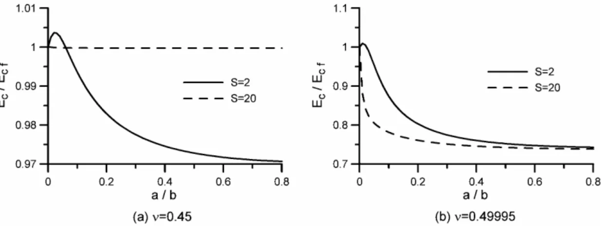
which is the compression modulus of full-circular layers presented by Tsai and Lee (1998), denoted as Ecf here. The compression modulus of hollow-circular layers normalized to the compression modulus of full-circular layers is plotted as a function of a /b in Fig. 4, which indicates that, under the same shape factor, stiffness reduction is negligible for the hollow-circular layers of smaller Poisson’s ratio (0.45). In general, the compression modulus decreases with increasing the radius ratio, but for the cases of S2 with very small a /b, the hollow-circular layers have higher stiffness than the full-circular layers. This is because the shape factor is also a linear function of the radius ratio as shown in Eq. (20).
The same shape factor means the layers of larger a /b have a larger b /t ratio. To study the effect of a central hole on the compression stiffness, Fig. 5 plots the normalized compression modulus under the same values of b/( t2 ), which is the shape factor of the bonded full-circular layers. For 0.45, the thicker layer has more stiffness reduction by the central hole under the same outer radius. But for 0.49995, the thinner layer has more stiffness reduction by the central hole under the same outer radius.
4. Vertical stress and shear traction
By using the pressure solution in Eq. (10), the effective vertical stress in Eq. (15) can be derived and is plotted in Fig. 6 as a function of r /b, where the effective vertical stress is normalized by the average compression stress . The figure shows that the vertical stresscEc is uniformly distributed in the layers with smallPoisson’sratio (0.45) and large shape factor (S 20). The vertical stress is symmetrical to the middle of annual thickness in the layers of large radius ratio (a/b0.5), but not in the layers of small radius ratio
) 01 . 0 /
(a b .
The shear strain in the bonding surface between the elastic layer and the rigid plates, which represents the magnitude of shear traction on the elastic layer, is
) 4 ( ) 2 / , ( )
( u r
t t r r rz
c
(28)
where the horizontal displacement in the middle plane is (Tsai and Lee, 1998)
pr
u 2 ,
2
3
(29)
Using the solution of the effective pressure in Eq. (10), the shear strain is derived as
1 ( ) ( ) ( ) ( ) ( ) ( )
) 1 ( ) 1 (
12 )
(
1
1 h b K r
b a a h r I b bh a a b h
a S r
I I
K K
c
c
(30)
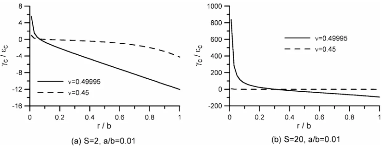
The distribution of shear strain along the radius is plotted in Fig. 7 for a/b0.01, which reveals that the shear traction increases more sharply near the inner edge in the layers of
49995 .
0
, especially for S20, but such sharp increment in shear traction does not happen in the layers of a/b0.5 plotted in Fig. 8. Both figures show that the layers of largershapefactororlargerPoisson’sratio havelargersheartraction.
As shown in Figs. 7 and 8, most of the bonded layers have the maximum shear traction at the inner edge, except for the layers of small shape factor (S 2) and small radius ratio
) 01 . 0 /
(a b , where the maximum shear traction occurs at the outer edge. The shear strain at the inner edge r isa
1 1 ( ) ( ) ( ) ( )
) 1 ( ) 1 (
12 )
(
1
1 a h b K a
I b b h a b
a S a
I K
c
c
(31)
The shear strain at the outer edge rb is
b
b a K a h b I a b h
a S b
I K
c
c 1 ( ) ( ) ( ) ( )
) 1 ( ) 1 (
12 )
(
1
1
(32)
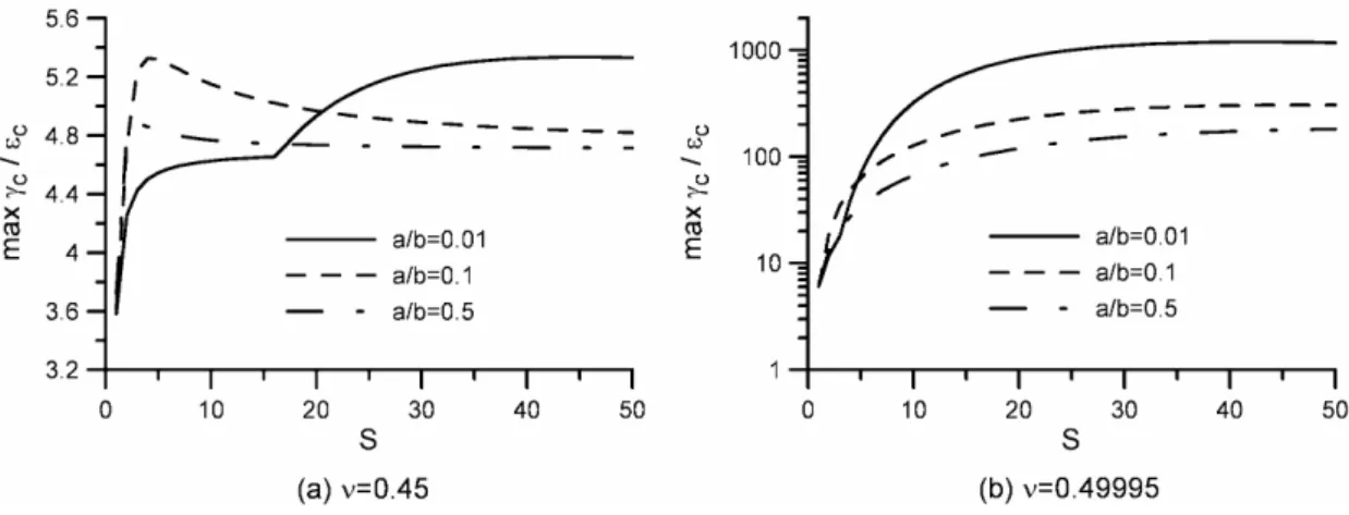
The maximum bonding shear strain is plotted in Fig. 9 as a function of shape factor, which indicates that the maximum bonding shear strain increases with increasing the shape factor except for the layers of a/b0.1 and a/b0.5 with 0.45. For the layers of large shape factor, the maximum shear strain increases with decreasing the radius ratio. The effect
of a central hole on the maximum bonding shear strain is shown in Fig. 10. For the layers of 45
.
0
, the radius of the central hole has little effect on the maximum shear strain. But for the thin layers with 0.49995, the maximum shear strain dramatically increases with reducing the radius of the central hole.
5. Conclusion
On the basis of the two kinematic assumptions, i.e. horizontal planes remain planar and vertical lines become parabolic after deformation, the hollow-circular elastic layers bonded between rigid plates are analyzed through a theoretical approach to find the closed-form solutions of the mean pressure in the elastic layers under compression forces, from which the compression stiffness can be derived. The analysis has no limitation on Poisson's ratio, so that the effect of Poisson's ratio can be studied. The bonded elastic layer can achieve high compression stiffness by using high shape factor and high Poisson’sratio.For the elastic layers of incompressible material, the compression stiffness is derived through the asymptotic approach, which provides a more accurate solution. The solution of the previous research, by directly neglecting the bulk compressibility, is accurate only when the shape factor is large.
Under the same ratio of the outer radius to the thickness, the compression stiffness decreases with increasing the inner radius. This stiffness reduction becomes more prominent when thePoisson’sratio iscloseto 0.5.Thecentralholeofthe layersmay createhigh shear traction, especially forthelayersoflargeshape factorwith thePoisson’sratio nearto 0.5.
Smaller central holes will generate higher shear traction.
References
Chalhoub, M. S., Kelly, J. M., 1990. Effect of bulk compressibility on the stiffness of cylindrical base isolation bearings. International Journal of Solids and Structures 26, 734-760.
Chalhoub, M. S., Kelly, J. M., 1991. Analysis of infinite-strip-shaped base isolator with elastomer bulk compression. Journal of Engineering Mechanics, ASCE, 117, 1791-1805.
Constantinou, M. C., Kartoum, A., 1992. Analysis of compression of hollow circular elastomeric bearings. Engineering Structure, 14, 103-111.
Gent, A. N., Lindley, P. B., 1959. The compression of bonded rubber blocks. Proceeding of the Institution Mechanical Engineers 173, 111-117.
Gent, A. N., Meinecke, E. A., 1970. Compression, bending and shear of bonded rubber blocks. Polymer Engineering and Science 10, 48-53.
Ling, Y., 1996. An approximate solution for the compression of a bonded thin annular disk.
Journal of Applied Mechanics, ASME, 63, 780-787.
Ling, Y., Engel, P. A., Brodsky, W. L., 1995. Compression of bonded annular rubber blocks.
Journal of Engineering Mechanics, ASCE, 121, 661-666.
Kelly, J. M., 1997. Earthquake-Resistant Design with Rubber, second ed. Springer-Verlag, London.
Koh, C. G., Kelly, J. M., 1989. Compression stiffness of bonded square layers of nearly incompressible material. Engineering Structures 11, 9-15.
Koh, C. G., Lim, H. L., 2001. Analytical solution for compression stiffness of bonded rectangular layers. International Journal of Solids and Structures 38, 445-455.
Lindley, P. B., 1979. Compression module for blocks of soft elastic material bonded to rigid end plates. Journal of Strain Analysis 14, 11-16.
Tsai, H.-C., 2005. Compression analysis of rectangular elastic layers bonded between rigid plates. International Journal of Solids and Structures 42, 3395-3410.
Tsai, H.-C., Lee, C.-C., 1998. Compressive stiffness of elastic layers bonded between rigid plates. International Journal of Solids and Structures 35, 3053-3069.
Fig. 1: Hollow-circular elastic layer bonded between rigid plates under compression load.
Fig. 2: Compression modulus of hollow-circularlayersvaried with Poisson’sratio.
Fig. 3: Compression modulus varied with shape factor for incompressible material.
Fig. 4: Normalized compression modulus varied with radius ratio under fixed shape factors.
Fig. 5: Normalized compression modulus varied with radius ratio under the fixed ratio of outer radius to thickness.
Fig. 6: Distribution of normalized vertical stress along radius.
Fig. 7: Distribution of bonding shear strain along radius (a b0.01).
Fig. 8: Distribution of bonding shear strain along radius (a b0.5).
Fig. 9: Maximum bonding shear strain varied with shape factor.
Fig. 10: Maximum bonding shear strain varied with radius ratio.
計劃成果自評
本研究利用彈性力學理論推導出黏著於剛性板的空心圓形彈性層的壓縮勁度公式 解,這壓縮勁度公式因考慮了體積壓縮性,可適用於任何柏松比的彈性層,因此可更精 確的計算出空心圓形多層膠墊的軸向壓縮勁度,並可供非橡膠類的彈性層使用。比較由 壓縮勁度公式計算出的理論解,與用有限元素分析法計算出的數值解,兩者極為接近,
因此壓縮勁度公式可適用任何參數範圍。本研究也對黏著於剛性板的空心圓形彈性層作 應力分析,推導出空心圓形彈性層受軸向壓力時在垂直向的正應力分佈,彈性層和剛性 板黏著面的剪應力分佈。由這些應力分佈可找出其最大值,以供設計空心圓形多層膠墊 時使用。
這些研究成果均達到原計劃預期目標,將可在學術期刊發表。