行政院國家科學委員會補助專題研究計畫 ■成果報告
□期中進度報告 高階光子技術發展與應用
計畫類別:■個別型計畫 □整合型計畫 計畫編號:NSC97-2218-E-011-007-MY3
執行期間:2008 年 08 月 01 日至 2011 年 10 月 31 日 執行機構及系所:國立台灣科技大學電子工程系 計畫主持人:Gerd Keiser
成果報告類型(依經費核定清單規定繳交):□精簡報告 ■完整報告
本計畫除繳交成果報告外,另須繳交以下出國心得報告:
■赴國外出差或研習心得報告
□赴大陸地區出差或研習心得報告
□出席國際學術會議心得報告
□國際合作研究計畫國外研究報告
處理方式:除列管計畫及下列情形者外,得立即公開查詢
□涉及專利或其他智慧財產權,□一年□二年後可公開查詢 中 華 民 國 101 年 01 月 15 日
附件一
國科會補助專題研究計畫成果報告自評表
請就研究內容與原計畫相符程度、達成預期目標情況、研究成果之學術或應用價 值(簡要敘述成果所代表之意義、價值、影響或進一步發展之可能性)、是否適 合在學術期刊發表或申請專利、主要發現或其他有關價值等,作一綜合評估。
1. 請就研究內容與原計畫相符程度、達成預期目標情況作一綜合評估
■ 達成目標
□ 未達成目標(請說明,以 100 字為限)
□ 實驗失敗
□ 因故實驗中斷
□ 其他原因 說明:
2. 研究成果在學術期刊發表或申請專利等情形:
論文:■已發表 □未發表之文稿 □撰寫中 □無 專利:□已獲得 ■申請中 □無
技轉:□已技轉 □洽談中 ■無 其他:(以 100 字為限)
附件二
3. 請依學術成就、技術創新、社會影響等方面,評估研究成果之學術或應用價 值(簡要敘述成果所代表之意義、價值、影響或進一步發展之可能性)(以 500 字為限)
1. Eleven papers were published in SCI journals, 3 manuscripts submitted to SCI journals are under review, and 17 conference papers were presented.
2. Two Taiwan and two US patent applications were submitted and are pending. The patents describe a novel efficient and effective method for fault-detection and fault-isolation methods for WDM networks in intelligent buildings. This is also of importance to fiber-to-the-premises (FTTP) access networks for which Taiwan is designing and manufacturing a series of photonic components.
3. In addition, an evaluation was made of FTTP network connector reliability when they are exposed to acid rain conditions and another evaluation examined practical issues related to mating glass and plastic fibers for in-building network applications. The evaluation included connectors made in Taiwan and two other countries.
4. Many photonic components developed over the past two decades by the telecom industry can be applied in biophotonics and biomedical systems for healthcare diagnosis, medical light therapy, and imaging, and for life sciences research. Work in this area examined how such optical components being made in Taiwan can be applied in biophotonics, medical research, and healthcare systems that are widely used in telecom networks.
5. In the last few years, numerous efforts have been devoted to the study of nanostructured materials. The remarkable electronic, photonic, chemical, and mechanical properties of these materials have been explored for developing a variety of nano-devices and nano-systems that can be used in bio-sensing, photovoltaic, and optoelectronic applications. Thus, because this is a rapidly growing industry in Taiwan, some of the NSC project team members supported the nanosciences group at NTUST in studies on nanostructures.
6. As part of the task devoted to designing unique LED light-distributing lenses, an
illumination-pattern and spectral measurement system was purchased and set up for verifying wavelength-dependent light distribution patterns from novel LED lens designs. These lens designs are of importance to the growing Taiwan LED manufacturing industry. In addition, the associated measurement system will be available for further investigations by component design groups.
7. Besides having significant benefits to different segments of the telecom industry in Taiwan and elsewhere, the studies done on this NSC project also benefited engineering students. The students participating in the project gained valuable experience in learning different aspects of telecom networks. These educational aspects will help them in a career path in the telecom and biophotonics industries.
Abstract Keywords
I. Introduction II. Project Overview
III. Details on Results and Achievements of Project Activities
a. Status monitoring and fault identification for intelligent buildings networks b. Characteristics of telecom optical devices for biomedical applications c. Improvements in the performance of optical fiber networks
d. Corrosion effects of acid rain on outdoor optical patch cord connectors e. Use of photonic devices for in-home healthcare monitoring
f. Tunable erbium-doped fiber ring lasers for a WDM access network g. Support of studies on nanostructures
h. Practical applications of indoor optical fiber cables
i. Simplified designs of precise TIR lenses for LED lighting applications IV. Journal and Conference Papers Published; Patents Applied
V. Self-Assessment of the Technology Developed VI. Technology Promotion
VII. Conference Reports
VIII.
Abstract:
This project investigated advanced photonic technology developments and their applications to improve
existing enterprises and to advance emerging industries that are being researched and implemented worldwide.
In part, this work examined the characteristics and functions of some passive and active optical components being made in Taiwan. The results of this NSC project show how these and other devices can be applied in areas such as integrated tenant services for intelligent buildings, radio-over-fiber networks, highly efficient fault detection and isolation methods for telecom networks, and biophotonics instruments for life sciences and healthcare.
Keywords: WDM PON, intelligent building, healthcare monitoring, biophotonics, OCT coupler, connector reliability, TIR lens, nanostructures
Section I: Introduction
The past years have seen rapid advances and applications of optical fiber communications technology to satisfy the ever-growing demands of bandwidth hungry telecom equipment. This scenario has resulted in the development of a wide range of photonic devices ranging from simple to highly sophisticated designs for the telecom industry.
To keep up with new bandwidth demands from personal communication and entertainment devices such as high-end smart phones, tablet computers, and Internet-enabled TVs, new photonics components and novel techniques for their application are required to increase the capacity and the signal fidelity on optical fiber lines. In particular, novel transmission and monitoring methods are needed in fiber-to-the-premises (FTTP) access networks that are based on wavelength-division multiplexing (WDM) technology. Thus, part of this NSC project on Advanced Photonic Devices addresses this issue. Included in that study are tests of
performance enhancement methods, development of tunable fiber lasers, development of novel fault-detection and fault-isolation methods for WDM networks in intelligent buildings, and analyses of energy consumptions in access and home networks. In addition, an evaluation was made of FTTP network connector reliability when they are exposed to acid rain conditions and another evaluation examined practical issues related to mating glass and plastic fibers for in-building network applications.
The extensive worldwide activities involved with developing optical fiber telecommunication systems over the past two decades has resulted in a large portfolio of passive and active optical components. Many of these components can be applied in biophotonics and biomedical systems for healthcare diagnosis, medical light therapy, and imaging, and for life sciences research. Work in this area on this NSC project examined the characteristics and functions of a variety of optical components being made in Taiwan that are widely used in telecommunication networks. The goal is to show how these devices can be applied in biophotonics, medical research, and healthcare systems and how Taiwan manufacturers and applications organizations can benefit from new worldwide market opportunities.
The manufacture of light emitting diodes (LEDs) is a major business in Taiwan. For lower power consumption, LEDs are highly attractive for many new green technology applications, and they also have the advantages of good reliability, long lifetimes, and a variety of color selections. Therefore, they can be applied
widely to areas such as spotlights, automobile taillights, indicators on equipment, or road lights. However, for specific application requirements an LED needs collection optics to capture and redistribute the LED light.
Since different products demand unique light distributions, great importance is placed on designing the LED light-distributing lens. Of particular interest is the use of a total internal reflection (TIR) lens for LEDs. Thus part of this NSC project was devoted to devising a simplified design method for creating practical photonic devices and a light pattern and spectral measurement system for evaluating such designs was purchased and set up.
In the past few years, numerous efforts have been devoted to the study of nanostructured materials.
The remarkable electronic, photonic, chemical, and mechanical properties of these materials have been explored for developing a variety of nano-devices and nano-systems that can be used in bio-sensing,
photovoltaic, and optoelectronic applications. Thus as part of this NSC project on Advanced Photonic Devices, some of the project team members supported the nanosciences group at NTUST in studies on nanostructures.
Besides having significant benefits to different segments of the telecommunications industry in Taiwan and elsewhere, the studies done on this NSC project also benefited engineering students. The students
participating in the project tasks gained valuable experience in learning different aspects of
telecommunications networks. These factors include understanding and analyzing performance characteristics, appreciating and evaluating the importance of various operational parameters, learning how to measure and assess reliability criteria, and becoming familiar with the use of communication system test equipment. These educational aspects will help them in a career path in the telecommunications industry. In addition, graduate students participating in this NSC research project were encouraged to enroll in courses such as Photonic Systems Designs, Optical Networking, and Biophotonics. These courses were offered at NTUST to train development and system applications engineers in Taiwan.
Section II. Project Overview
The NSC Project Team Members participated in nine research categories that resulted in eleven published and three pending SCI journal papers, 17 international conference papers, and four patent applications. The names of these papers and patents are given in the publication list in Section IV. The task categories are summarized in the following paragraphs. Further details on achievements for each of these categories are presented in Section III: Details of Project Activities.
1. Status monitoring and fault identification for intelligent buildings networks:
i. This task examined a concept for fault detection and isolation in a wavelength-division-multiplexed passive optical network (WDM PON) in order to realize a highly reliable communication network.
The system is intended for communication between a central office and an intelligent building or an intelligent campus (for example, an office park, healthcare complex, university, shopping center).
ii. The work resulted in two conference papers, one SCI journal paper, and four patent applications.
2. Characteristics of telecom optical devices for biomedical applications:
i. Many photonic components that were developed for use by the telecom industry are being used in biomedical optical systems. The main endeavor of this task investigated the effects of the
wavelength-dependent characteristics of an optical coupler on the accuracy of measurements in optical coherence tomography.
ii. The work resulted in four conference papers. An SCI journal paper is in preparation.
3. Improvements in the performance of optical fiber networks: This task provided support to the optical communication network group to realize improvements in the performance of WDM-PONs. The following research was pursued:
i. A low-cost passive optical network scheme for intelligent buildings located in areas having difficulty with wireless signal reception
ii. A scheme to stabilize the optical channel frequency and enhance bidirectional transmission.
iii. Energy consumption analyses in hybrid access and home networking networks.
iv. The work resulted in three conference papers and three SCI journal papers. Another SCI journal paper has been submitted.
4. Corrosion effects of acid rain on outdoor optical patch cord connectors:
i. This task examined the degradation of optical fiber connectors when they are exposed to acid rain.
This is especially important for outdoor links such as are found in drop cables for access networks.
The results will help manufacturers in Taiwan understand the importance of long-term environmental effects on photonics components used for outdoor telecom equipment.
ii. The work resulted in two conference papers. An SCI journal paper is in preparation.
5. Use of photonic devices for in-home healthcare monitoring:
i. Because the percentage of elderly people of Taiwan and many other countries is continuously increasing, an important factor is how to remotely monitor the wellbeing of elderly and disabled people in their homes. To address this issue, this task examined inexpensive methods for photonic and wireless home healthcare monitoring.
ii. The work resulted in three conference papers.
6. Tunable erbium-doped fiber ring lasers for a WDM access network: This task provided support to the optical fiber components group. The following research was pursued:
i. A widely wavelength-tunable erbium-doped-fiber laser located at a central office was investigated for the bidirectional high-speed performance testing of WDM access networks in which
injection-locked Fabry-Perot laser diodes located at optical network units are used for upstream transmissions.
ii. We investigated a stable, wideband, and tunable directly modulated fiber ring laser by using a reflective semiconductor optical amplifier and an optical tunable filter.
iii. The work resulted in one conference paper and three SCI journal papers.
7. Support of studies on nanostructures:
i. Pattern growth and characteristics of flower-like RuO2 nanostructures ii. Effect of nanoscale ripples on the formation of ZnO quantum dots iii. The work resulted in two SCI journal papers.
8. Practical applications of indoor optical fiber cables:
i. The extension of optical links deeper into homes and buildings is putting an emphasis on coupling both plastic and glass multimode indoors fibers in a low-cost low-loss manner. This task checked the statistics of connecting a variety of such fibers to get an idea of what can be expected in a real-world environment.
ii. The work resulted in one conference paper.
9. Simplified designs of precise TIR lenses for LED lighting applications:
i. This work presents a simple geometric optics approach that allows a precise freeform TIR lens to be easily and quickly designed, analyzed, and fabricated for both collimated and uniformly distributed LED light emission patterns.
ii. The work resulted in one conference paper. Two papers have been submitted to SCI journals.
Section III. Details on Results and Achievements of Project Activities
This section gives details on the results and achievements accomplished within each of the nine research categories described in Section II.
1. Research Project Number 1: Status monitoring and fault identification for intelligent buildings networks
A. Project overview
Communication networks within modern buildings have undergone a significant change in the past two decades. This change is due to factors such as the need to control rising energy and facility operations costs, increasing demands of building operators and tenants for a highly flexible and efficient intra-building communications infrastructure, and the desire to have an environment that is comfortable, safe, and secure.
This has resulted in proposed intra-building network configurations that not only provide a sophisticated communications infrastructure but also integrate many autonomous building-control and status-monitoring functions, such as lighting, heating and air conditioning, security, and safety systems, into a single networked function. Structures with such networks are referred to as intelligent buildings.
The fundamental goal of an intelligent building is to efficiently and reliably merge various building management and information technology (IT) systems onto a single Internet Protocol (IP) or Ethernet network in order to optimize the overall building performance and to simplify facility operations. The data from such an integrated network can be converted into an IP format by a centralized control system and then can be delivered to a monitoring station located either in a central office (CO) or in the building.
Since many different building operations are merged into a single network, a major consideration is how to ensure the reliability of the network. The topic of this task is the development of a status-monitoring and fault-diagnosis scheme for verifying the integrity of an information transmission system in an intelligent building. The network employs wavelength division multiplexing (WDM) technology with signals being sent over a bidirectional optical access network. The integrity of the intelligent building network is verified from a central office (CO).
The method described here uses one wavelength band (e.g., the L band) for downstream traffic and monitoring signals and another non-interfering wavelength band (e.g., the C band) for the upstream signals. The assignment of these wavelength bands is flexible. For example, the spectral bands assigned to the downstream and upstream signals can be interchanged and another wavelength band, such as the 1650-nm region discussed in ITU-T L.41 and L.53, could be used for status-monitoring signals or optical time domain reflectometer (OTDR) signals.
The particular wavelength bands used for the concept description and experimental demonstration were selected based on using photonic components that were available in our laboratory. For example, to generate a
troubleshooting signal an inexpensive single-wavelength C-band OTDR was used. In addition, this work concentrates on the physical-layer functions of the monitoring and trouble-shooting method, which is the novel aspect of this concept. The higher-level functions needed for processing acknowledgements from users and for enabling the OTDR fault-locating function are for future investigation. The design is readily applicable to a localized WDM passive optical network (PON), such as in a campus environment or in a large multiple-tenant building, where local power exists for operating the optical amplifiers and the low power consuming switch modules used in this concept. If desired, the need for local power can be eliminated through the use of a remote powering scheme.
The main features of this status-monitoring and fault-diagnosis structure include:
(1) Real-time remote monitoring and fault diagnosis from a CO working in parallel with the user traffic (2) Continuous monitoring on functioning lines while failed lines are being diagnosed
(3) Independently operating the monitoring signals and the fault-diagnosing signals
(4) Expandable monitoring and fault diagnosis in which more wavelengths can be assigned to additional users
(5) Amplification of the traffic and monitoring signals to get a larger power budget for possible usage in an extended WDM PON
(6) A fault diagnosis system in which the OTDR is used only when a link fault occurs.
B. System operation concept
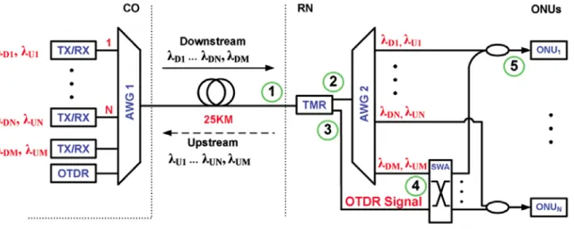
Fig. 1 illustrates the overall system concept. A single bidirectional optical fiber interconnects a set of N optical transceivers (TX/RX) in a central office with a set of N optical network units (ONUs) at user locations in an intelligent building. The remote node (RN) can be located within the intelligent building. At the CO, the N downstream traffic signals (designated by λD1,…,λDN) and a network-status monitoring wavelength λDM are combined onto a fiber using an arrayed waveguide grating (AWG) designated by AWG1.
Figure 1. Top-level concept of the status-monitoring and fault-diagnosis method.
Upon arriving at the RN at point 1, these signals pass through the traffic and monitoring-signal router (TMR) and are demultiplexed at point 2 by another AWG designated by AWG2. The demultiplexer AWG2 distributes the individual traffic signals to the designated ONUs (point 5) and shunts the monitoring signal from point 3 to
a switch array (SWA) at point 4. Individual routing elements in the SWA select either a standard monitoring signal or an OTDR signal, which will be used to diagnose the physical integrity of a specific traffic signal path.
That is, the OTDR signal is substituted for the monitoring signal on faulty lines during troubleshooting events.
The structural details of the TMR and the SWA are described below. In the upstream direction, AWG2 multiplexes traffic signals (designated by λU1,…,λUN) coming from the ONUs together with the upstream monitoring signal λUM and directs this combined signal to the TMR (point 2).
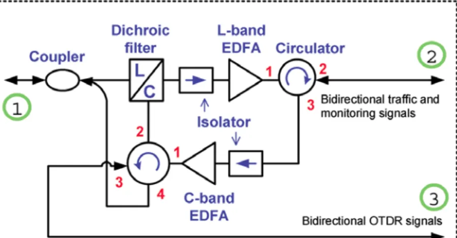
Figure 2. Layout schematic of the TMR.
Fig. 2 shows what paths the three types of upstream and downstream signals follow through the TMR. As the downstream traffic and monitoring signals enter the TMR at point 1, they pass sequentially through an optical coupler, a dichroic L-band/C-band filter, an optical isolator, an L-band EDFA, and a three-port optical circulator. The L-band EDFA compensates for component losses in the downstream path. For example, in this setup the losses are 5.0 dB for each AWG, 3.8 dB for the optical coupler, 0.4 dB for the dichroic filter, 0.4 dB for the optical isolator, and 0.8 dB for the optical circulator. After amplification, the downstream signals pass through an optical circulator (exiting from port 2) and enter the demultiplexer AWG2. As the upstream traffic and monitoring signals enter the TMR at point 2, they pass sequentially through the three-port optical circulator (entering at port 2 and exiting at port 3), an optical coupler, a C-band EDFA, a four-port optical circulator (entering at port 1 and exiting at port 2), and the dichroic filter, and then go to the CO from point 1.
When an OTDR troubleshooting signal is invoked, this signal is transmitted in the C-band from the OTDR and is multiplexed onto the fiber by AWG1. Upon entering the TMR at point 1, the dichroic filter directs the OTDR signal to the four-port optical circulator (entering at port 2 and exiting at port 3) and then to the SWA at point 3. When the returning OTDR signal reaches the TMR at point 3, it enters port 3 and exits at port 4 of the four-port optical circulator and then returns to the OTDR from point 1 of the TMR. Thus the whole OTDR trace will go through neither the downstream nor the upstream optical amplifiers of the TMR. This condition is necessary because the OTDR cannot determine a fault location if the signal reflected from the fault is amplified and it can only calculate the fault distance along one traffic signal path at a time.
As Fig. 3 illustrates, the downstream L-band traffic and monitoring wavelengths arriving at an ONU at point 5 pass through the dichroic optical filter and are separated and directed to the ONU data and monitoring receivers, respectively, by means of the optical circulator (OC) and fiber Bragg grating (FBG) combination. The
C-band upstream traffic and monitoring signals originating at an ONU are combined with an optical coupler and are inserted onto the fiber line by means of the dichroic filter.
Figure 3. ONU configuration for sending and receiving traffic and monitoring signals.
In normal operation the downstream monitoring signal will send status-request messages continuously to all nodes of a building and will get acknowledgements from the upstream monitoring signal of all nodes as well.
The system monitors all nodes simultaneously in real time. When one of the nodes fails, the system will set up an OTDR trace test to determine fault possibilities of the failed node. Because an OTDR trace is a physical test, only a single path is tested at one time. When a fault condition is reported to the CO, the monitoring signal transmitter at the CO starts sending a message to all ONUs. The wavelength λDM of the downstream L-band monitoring signal will follow the same path through the TMR module as the downstream information signal and will be demultiplexed to one port of AWG2, as shown by point 4 in Fig. 1.
As Fig. 4 shows, the downstream monitoring signal coming from AWG2 enters an optical splitter at point 4 in the SWA, which distributes the signal equally to each top port of the set of N 21 optical switches (OSW).
Based on the ONU status information contained in the upstream monitoring signal, the SWA control algorithm decides on whether to select the downstream monitoring signal or the OTDR test signal to check each ONU. In a normal condition, the SWA switches are set to have all the ONUs receive the downstream monitoring signal.
The ONUs take turns to send upstream acknowledgements in a time-division-multiplexed (TDM) mode. The speed of the upstream TDM-based monitoring signal is low compared to the traffic speed, for example, a 10-Mb/s monitoring-signal rate is only 0.1 percent of a 10-Gb/s traffic rate.
Figure 4. Configuration of the SWA at the RN.
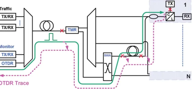
The CO control system continuously analyzes the monitoring data to identify failures and to invoke use of a troubleshooting OTDR signal for a failed link. The crosses in Fig. 5 indicate some possible failure points. If more than one location is affected, the system will check the failed nodes sequentially by their priority. Fig. 5 shows that the OTDR trace will test an ONU by following the solid line through the two AWGs and the SWA.
As can be determined from Fig. 4, when the path of ONUj has a problem the monitoring system can easily manipulate the troubleshooting signal by setting the OTDR path through the 1N OSW so that it is connected to the jth 21 OSW, which then is set to pass the OTDR signal for checking ONUj. The dashed line in Fig. 5 shows that after being reflected from a fault location, the OTDR signal goes back to the OTDR equipment following the same path along which it came.
Figure 5. Downstream and upstream paths followed by the OTDR troubleshooting signal.
The monitoring signal and the OTDR test signal work independently. The system continues to maintain operation of good ONUs whether broken nodes are being diagnosed or not. More wavelengths can be added when the number of ONUs is increased. One just needs to extend the capacity of the 1N OSW and the number of 21 OSWs to equal the total number of nodes N. The advantage of an OSW is that the insertion loss is less than 1.5 dB even if the number of ONUs increases.
Experimental tests show that excellent transmission performance plus independent fault monitoring, detection, and location identification are achieved for both downstream and upstream traffic at 10 Gb/s.
2. Research Project Number 2: Characteristics of telecom optical devices for biomedical applications
Many photonic components that were developed for use by the telecom industry are being used in biomedical optical systems. This task investigated the effects of the wavelength dependent characteristics of a telecom optical coupler on the accuracy of measurements in optical coherence tomography (OCT).
Optical coherence tomography is a real-time optical imaging method that can create high-resolution, cross-sectional tomographic images of the internal structure of biological and other materials. OCT uses low-coherence interferometry detection and correlation based on the principles of a Michelson interferometer to measure the echo time delay of backscattered or back-reflected light. In OCT systems the processes for
determining the axial and transverse resolutions are decoupled. Whereas the transverse resolution is determined by the beam focusing capabilities of the optics, the axial resolution depends on the coherence length of the optical source. Light with a shorter coherence length (or broader spectral bandwidth) will yield a more precise axial resolution.
A number of variations exist for implementing an OCT system. First, the Michelson interferometer can use either free-space optics or a single-mode 2x2 optical coupler. In terms of the detection method, the two main methods are time-domain and fourier-domain OCT. In this study we used an optical fiber coupler and a fourier-domain OCT setup.
Because the fused-fiber optical coupler is a key component in an OCT setup, it is of interest to determine what effect any wavelength-dependent asymmetry in its operational characteristics has on the OCT system performance. Ideally the coupler should have a splitting ratio that is independent of wavelength. However, all optical fiber couplers have some variation in transmission loss as function of wavelength. Here a detailed simulation and experimental investigation was made to determine what effects the wavelength-dependent characteristics in different arms of an optical coupler have on the accuracy of OCT measurement. Of particular interest was the effect on OCT performance when interchanging the input arms of a 50/50 splitting-ratio coupler that is designated as being symmetric.
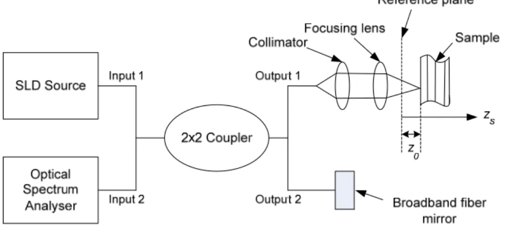
Figure 6. Schematic of experimental setup of FDOCT system
The experimental setup for frequency-domain OCT (FDOCT) is shown in Fig. 6. The output of the broadband super-luminescent-diode light source (SLD 1300 nm) is split into two beams by the 2x2 fiber coupler, and each beam is directed towards one arm of a Michelson interferometer. The end of one arm of the Michelson interferometer consists of a broadband fiber mirror and the sample of interest is at the end of the other arm. The reflected beams from the sample and the broadband mirror are collinearly combined by the fiber coupler and directed towards the optical spectrum analyzer (OSA) (Anritsu MS9710C). The detected output is the power spectrum resulting from the coherent interference between the two reflected signals.
For the experimental setup shown in Fig. 6, we use a broadband SLD source with λ0 = 1300 nm and a full-width half-maximum (FWHM) of Δλ = 58 nm. The output power of the SLD source is 1mW. The sample used is a glass sample and is kept at a distance of 1 cm from the reference plane (i.e., z0 = 1 cm). The coupler used is a 1300-nm single-mode fiber (SMF) coupler. The interference signal is detected at the OSA. The resolution of the OSA is 1 nm. The SLD source has a Gaussian spectrum with maximum output power of -18.88 dBm at 1300 nm.
In an OCT system the axial resolution (Δx) depends on the FWHM (Δλ) through the relationship
x 2ln2
20
(1)
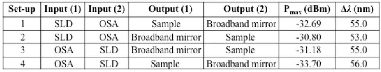
Thus the goal of the experiments is to examine the change in Δx resulting from variations in Δλ under various orientations of the coupler. The measurements for the different orientation setups of the coupler are depicted in Table 1. For example, in setup 4 the inputs to the fibers used in setup 1 are exchanged. As shown in Table 1, the maximum power detected at the OSA varies from -30.80 to -33.70 dBm and the FWHM varies from 53.0 to 56.0 nm. The detected OSA outputs for the different configurations of the coupler are shown in Fig. 7. The detected outputs at the OSA have the same envelope as the source spectrum, but with different maximum powers and FWHM values. Using Eq. (1), it can be seen that depending on the optical coupler orientation, the FWHM variations can result in axial resolution variations between 2 to 4 percent.
Table 1. Measurements at OSA for different configurations of SMF 1300 nm coupler
3. Research Project Number 3: Improvements in the performance of optical fiber networks
This task provided support to the optical communication network group to realize various improvements in the performance of WDM-PONs.
A. Investigation of a low-cost passive optical network scheme for intelligent buildings located in areas having difficulty with wireless signal reception
A low-cost passive optical network scheme is presented for intelligent buildings located in areas having difficulty with wireless signal reception. The network can simultaneously broadcast
digital-video-broadcasting-terrestrial (DVBT) signals and can transmit high-speed data bidirectionally using a Fabry-Pérot laser diode (FP-LD), which is injection-locked by a vertical cavity surface-emitting laser
(VCSEL). Results were determined for the broadcast of DVB-T signals over an 1-km multimode fiber (MMF) and for non-return-to-zero (NRZ) data over a 25-km single mode fiber (SMF). Downstream and upstream transmission bit rates are 10 Gb/s and 1.25 Gb/s, respectively. Maintaining TV signal quality at 40%, receiver sensitivities are -20.2 dBm and -22.58 dBm for downstream and upstream transmissions, respectively. In addition, the constraint of injection locking and the limitation of optical power also were analyzed.
B. Investigation of a scheme to stabilize the optical channel frequency and enhance bidirectional transmission
A scheme for simultaneous extinction-ratio enhancement, optical frequency stabilization, and wavelength reuse is proposed for reflective semiconductor optical amplifier-based wavelength-division multiplexed
passive optical networks to stabilize the optical channel frequency and enhance bidirectional transmission.
This is achieved by simply employing a single Fabry-Perot etalon at the optical line terminal rather than having one etalon at each optical network unit. Compared with the remodulation scheme that uses a 10-Gb/s optical signal with a 3-dB extinction ratio as a downstream optical signal and a seed light, our scheme shows improvements in power penalties greater than 1.8 dB and 1.4 dB for 10-Gb/s downstream and 1.25-Gb/s upstream signals, respectively, after transmission of 25 km at a bit-error-rate = 10-9. Moreover, a power
penalty of only 0.5-dB is observed in comparison to the two 1.25-Gb/s upstream bit-error-rate results based on using a continuous-wave seed light and a data-erased seed light.
4. Research Project Number 4: Corrosion effects of acid rain on outdoor optical patch cord connectors
The rapidly growing worldwide demands for high-speed Internet access has resulted in a tremendous increase in the number of subscribers connected to optical access networks. For example, there were over 20 million fiber-to-the-premises (FTTP) subscribers in Japan by 2010. In FTTP installations a number of reliability questions arise, since the optical connectors attached to drop cables running to the user premises are exposed to harsher conditions than the more traditional use of connectors in stable and benign indoor environments.
The long-term outdoor environmental effects on optical fiber connectors include conditions such as large temperature variations, water immersion, salt spray, and high humidity. Although a number of different optical connector designs exist for harsh outdoor field environments, such as for tactical military
communication links, connections to remotely located antennas, and telecom networks, such components tend to be more costly than standard telecom connectors.
Acid rain is a problem of current and future concern in the world. Acid rain affects human life in a variety of ways. Acidification of ground water and soil hampers the growth of plants and forests. In addition, acid rain also kills fish and damages buildings. Acid rain is caused by sulfur dioxide (SO2) and nitrogen oxide (NOx) forming in precipitation. Rainwater in equilibrium with carbon dioxide (CO2) in air is slightly acidic, with a pH of 5.6, while neutral water exhibits a pH of 7.0. Typical pH values of acid precipitation caused by anthropogenic emissions may be in the range of 3.5–5.0. Figure 7 shows a 10-year analysis of acid rain pH value in selected cities in the USA, Japan, and Taiwan.
Figure 7: Statistics of acid rain pH value in USA, Japan, and Taiwan (1998–2010).
The objective of this study was to examine and compare the reliability of various brands of optical fiber patch cord connectors in a corrosive and harsh outdoor environment, which includes acid rain, high
temperatures, and wind loading. The time to failure of several cable assemblies were examined under
accelerated test conditions when the assemblies were subjected to a simulated 3.9-pH acid rain, a temperature of 60℃, and a 100-rpm rotation rate. FC type connectors from three different manufacturers were compared.
During the evaluations following the tests, we checked for insertion loss variations, changes occurring on the tip shape of the patch cord connectors, and connector material degradations. The experimental results indicate that the time variation of the degree of corrosion damage on the connector results in various levels of rusting, occasional failures in fiber bonding, and a gradual increase of the insertion loss.
For performance evaluation tests, we selected patch cords with attached Ferrule connectors (FC) from manufacturers located in three countries (USA, Japan, and Taiwan). FC has been one of the most popular single-mode connectors for many years, and optical performance is guaranteed at less than 0.2 dB insertion loss. For the FC tip, we selected physical contact (PC) and angled PC (APC) types. The end face of the PC connector is convex and the core of the fiber is located at the high point of this surface. The end face of the APC connector is angled to achieve lower back reflection. Patch cord connectors from only three
manufacturers were selected due to the limitation of the test equipment capacity. In order not to disclose the names of the manufacturers, they were labeled as P, Q, and R. Twenty patch cord connector assemblies from each manufacturer were subjected to the environmental tests. For performance tests, insertion losses were measured and tip shapes were checked after periodic exposure intervals.
The samples were immersed for a total of 27 days and were examined at the following intervals: 0, 10, 17, 24, and 27 days. For degradation testing a 1550-nm laser was attached to the patch cord connector to measure the insertion loss with a power meter and the tip condition was observed with a microscope. Prior to starting environmental tests, since the insertion loss and surface of each connector is largely influenced by the
cleanliness of the connector plugs and the coupling adapter, proper cleaning procedures were followed for all components.
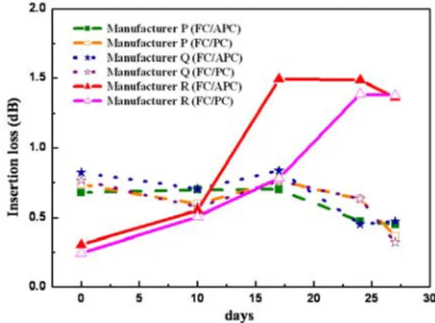
Figure 8 compares the insertion loss curves among the three manufacturers. Before starting
environmental tests, the insertion loss of the connector from manufacturer R is less than 0.3 dB, which is better than the devices from manufacturers P and Q. However, after 10-day environmental tests, the manufacturer R insertion loss becomes worse and after 27 days increases to above 1 dB. Connectors from vendors P and Q had more stable performances.
Figure 8: Experimental insertion losses of acid rain environment immersion test.
Figure 9 shows the tip conditions for a connector before and after testing. In most cases, the patch cord connector had a dirtier tip shape after tests. As a result of water or rust chemicals getting into connectors, the insertion losses changed and were unstable because of dirtier tips.
Figure 9: Comparison of connector tip conditions before and after 27 days of testing.
Summary: For FTTP networks the outdoor use of optical fiber patch cords with attached connectors presents a new reliability challenge. In our experiments, we examined the effects of acid rain immersion tests on connector insertion loss and tip shape. The tests were performed on FC type connectors from multiple vendors. The results show the potential problems that may arise in the field if standard connectors are used.
For connector reliability evaluation, we used accelerated immersion tests to simulate acid rain conditions. The time variation of the degree of corrosion damage on the connector results in rusting and a gradual increase of the insertion loss. Although connectors from some manufacturers showed stable optical performance during the tests, their reliability over time and under environmental stress remains a major concern, since some connectors failed after the tests. Thus, although the level of performance available today appears to be sufficient for applications dealing with controlled environments, further improvements are necessary for outdoor applications.
5. Research Project Number 5: Use of photonic devices for in-home healthcare monitoring
Because the percentage of elderly people of Taiwan and many other countries is continuously increasing, an important factor in this scenario is how to remotely monitor the wellbeing of elderly and disabled people in their homes. To address this issue, this task examined inexpensive methods for photonic and wireless home healthcare monitoring.
A. Telecom Device Applications to Biophotonic Systems: Huge research and development investments by telecom organizations have created a well established industry for fabricating highly reliable photonic components together with the capability to easily retool these components for specific applications. The strengths and unique capabilities of telecom photonic devices include component miniaturization, system integration into small packages (which house light sources, photodetectors, electronics, and fiber interconnects), high-speed lasers emitting extremely short pulses, high temporal resolutions, cost effectiveness,
and a physically thin and flexible transmission medium. Many biophotonic systems are employing photonic devices used by the telecom industry either in their existing format or in a repackaged or modified configuration. Regardless of the packaging, the operating principles of the biophotonic devices remain the same as for telecom applications.
In particular, these technologies can be applied to biomedical research, healthcare clinical procedures, and the increasing need to care for homebound patients. For example, as a result of escalating medical care costs and an increasing shortage of medical personnel, in-home healthcare is a challenging and growing problem in many countries worldwide. People who need special care within their homes include the elderly, persons recovering from surgery, strokes, or injuries, and individuals with chronic illnesses such as cancer, heart problems, diabetes, and memory loss. Areas of concern related to in-home healthcare include monitoring the health status of home-bound individuals, reporting any abnormalities to outside health clinics, offering online consultations with physicians or nurses, and educating the patients about their conditions.
This study examined how existing photonic devices can be used directly or in slightly modified versions in applications such as fluorescence spectroscopy, photonic-based biosensing, optical coherence tomography, photodynamic therapy, tissue engineering, and home healthcare.
B. Photonic Devices for In-Home Healthcare Monitoring: This study examined on-going investigations and future concepts for imbedding photonic technologies into various common household and personal items for monitoring purposes. Since typically people do not remember to take specific measurements of vital signs or do not like to bother with a specialized instrument, the goal in these photonic technology implementations is to incorporate automatic measuring functions into items that are used daily by the specific individual. These items can include telephones, dental night guards, and clothing. Photonic sensors also can be incorporated into areas such as bedding, floor mats, and furniture to sense patient movements.
6. Research Project Number 6: Tunable erbium-doped fiber ring lasers for a WDM access network
A. Bidirectional Transmission Using Tunable Fiber Lasers and Injection-Locked Fabry–Pérot Laser Diodes for WDM Access Networks: A widely wavelength-tunable erbium-doped-fiber laser located at a central office was investigated for the bidirectional high-speed performance testing of WDM access networks in which injection-locked Fabry-Perot laser diodes located at optical network units are used for upstream transmissions.
B. Tunable directly modulated fiber ring laser using a reflective semiconductor optical amplifier for WDM access networks: We investigated a stable, wideband, and tunable directly modulated fiber ring laser (TDMFRL) by using a reflective semiconductor optical amplifier (RSOA) and an optical tunable filter. For use in a bidirectional access network, the TDMFRL not only generates downstream data traffic but also serves as the wavelength-selecting injection light source for the Fabry-Pérot laser diode located at the subscriber site.
We experimentally demonstrated a bidirectional transmission at 1.25-Gb/s direct modulation over a 25-km single-mode fiber, thereby showing good performance in a wavelength division multiplexing (WDM) access network.
C. Tunable C- and L-band erbium-doped fiber ring lasers for performance testing of a wavelength-division multiplexing access network with injection-locked Fabry-Perot laser diodes: A simple, continuously tunable dual-wavelength erbium-doped fiber ring laser (TDEDFL) structure for applications in high-speed
communication systems was proposed and experimentally demonstrated. The dual-wavelength tuning range is 58 nm covering both the C-band and L-band from 1547 to 1605 nm. We can obtain not only a 45%
improvement over previously reported tuning ranges, but also can tune the wavelength of each lasing output independently. The power equalization of the dual-wavelength outputs is less than 1.5 dB. We obtain extremely stable power variation and wavelength fluctuation at room temperature. Using this fiber laser, a 10-Gb/s data transmission over a 25-km single-mode fiber (SMF) can be made available with a power penalty of 0.5 dB is demonstrated with this laser.
7. Research Project Number 7: Support of studies on nanostructures
A. Pattern growth and characteristics of flower-like RuO2 nanostructures: This study involved the selective growth of flowerlike RuO2 nanostructures, synthesized by metal organic chemical vapor deposition
(MOCVD), on Si substrates with pre-coating patterned Al and Fe catalyst films. To enhance the electron field-emission (FE) characteristics, the arrangement of the flower-like RuO2 nanostructures was a hexagonal configuration. The growth time of RuO2 nanostructures was adjusted to control the height of the RuO2
nanostructures, thereby leading to the ratio of the distance between every adjacent pair of flower-like Ru O2
nanostructures to the height of each RuO2 nanostructure to be fixed at about 2. The FE properties of the flower-like RuO2 nanostructures were characterized. The obtained threshold electric field (Eth) with a low value and a good FE stability demonstrated that the patterned flower-like RuO2 nanostructure is a promising material for FE applications.
B. Effect of nanoscale ripples on the formation of ZnO quantum dots: ZnO is one of the materials that exhibits the richest variety of nanostructures. Due to unique carrier confinement and surface effects,
low-dimensional ZnO nanostructures including nanobelts, nanowires, and quantum dots (QDs) have gained tremendous attention and found crucial applications in bio-sensing, photovoltaic, and optoelectronic
applications. Preparation of QDs on Si substrates without agglomeration and unwanted impurities are of special interests for in vivo bio-imaging applications. In this study nano-scale ripples on Si substrates were obtained by ion beam sputtering with beam energies ranging from 6 to 10 keV utilizing a capillary gas field ion source without beam scanning. The spatial wavelength of the nano-scale ripple increases as the ion beam energy increases, indicating that ion beam induced diffusion is the dominant diffusion mechanism for the formation of nano-scale ripples. ZnO QDs with diameters less than 20 nm and heights less than 4 nm can be prepared over the temperature range from 200-300 C.
Compared with QDs deposited on Si substrates without nano-scale ripple, the ion-beam textured substrate provides a wider processing window, improved size homogeneity of the QDs, and increased QD density. The formation mechanism of Zn QDs on Si substrates with nano-scale ripple is likely due to the presence of multiatomic steps that act as nucleation sites which facilitates the formation of ZnO QDs.
8. Research Project Number 8: Practical applications of indoor optical fiber cables
The extension of optical links deeper into homes and buildings is putting an emphasis on coupling both plastic and glass multimode indoors fibers in a low-cost low-loss manner. This task checked the statistics of
connecting a variety of such fibers to get an idea of what can be expected in a real-world environment.
The rapidly rising use of sophisticated electronic devices such as laptop PCs, tablet computers, smart 3G phones, and 3D electronic games is resulting in an ever-increasing bandwidth demand on indoor
communication links. Many studies have examined the problem of how to deliver high-quality digital services to all such devices that typically are scattered throughout a building. Among the candidate communication media are wireless links, glass single-mode optical fibers, glass multimode optical fibers (MMF), and multimode plastic optical fibers. Owing to their relatively low cost and ease of installation compared to single-mode fibers, multimode plastic optical fibers (POF) have become an attractive indoor medium. If such POF links are implemented properly, they have the following advantages: (1) the fibers are easy to
interconnect because of the larger core areas, (2) the use of POF links will reduce network costs because connectors are easier to attach to plastic fibers versus glass fibers, (3) and, compared to single-mode links, less expensive light sources can be used. In addition, the standard core sizes of POF include 50- and 62.5-μm diameters, which are compatible with the core diameters of standard multimode glass telecom fibers. Whereas multimode glass fibers used in early indoor installations had 62.5-μm core sizes to enhance the coupling performance of fiber-to-fiber interconnections, currently many premises installations use 50-μm core diameter fibers. This is done to accommodate Gigabit and 10-Gigabit Ethernet applications for which laser-optimized fibers, such as OM3 and OM4, can be run over distances of several hundred meters. In ISO 11801 the International Standards Organization has classified multimode fibers by the designations OM1, OM2, OM3, etc., which indicates the modal bandwidth of the MMF. OM3 and OM4 fibers provide sufficient bandwidth to support 10 Gigabit Ethernet over distances up to 300 m and 550 m, respectively.
This study task examined the practical implementation issues and pitfalls that can arise when attempting to interconnect POF and MMF to form the distribution network inside a building. A major concern is the random interconnection of glass and polymer optical fibers, which will occur in an actual application
environment inside a building. Of particular concern is the loss performance at joints between different types of fibers that are terminated with factory-installed connectors. These fibers could be either newly installed or they could already be in place in a building. In either case, the terminations on these fibers may not
necessarily prescribe to a strict termination-loss criterion.
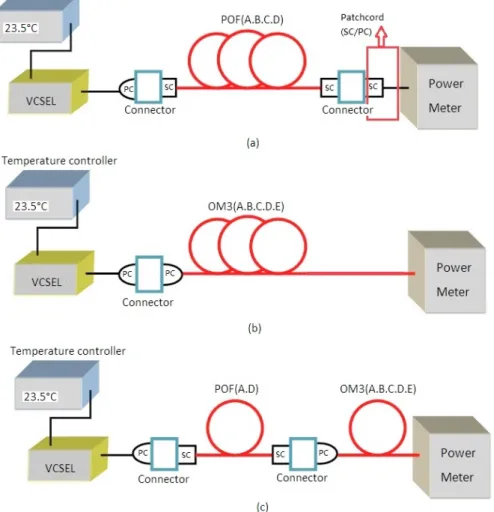
The experimental setup for measuring the losses in individual POF and OM3 segments is shown in Fig.
10. As shown in Fig. 10a for the POF segments, a PC-to-SC adaptor was used at the transmitter end to couple the VCSEL flylead to the POF. An optical fiber patch cord (1-m in length) was used to adapt the SC connector on the POF fiber segments to the PC connector on the power meter. For measuring the power losses in
individual OM3 segments, the OM3 fiber output end was attached directly to the power meter, as shown in Fig. 10b.
Figure 10. Configuration for characterizing link losses of individual and combinations of fibers; (a) Setup for measurement of POF segment losses, (b) Setup for measurement of OM3 segment losses, (c) Setup for measurement of paired fiber segment losses.
To fully characterize the connection losses all the POF and OM3 segments, loss measurements were made in both directions. In order to keep track of the direction in which the losses were measured, one end of the fiber segment was labeled 1 and the other end was labeled 2. For the loss testing, first a fiber segment was inserted into the setup (with end 1 being the input) and its loss was measured (with end 2 being the output).
This particular configuration was called “1 in, 2 out.” The segment was then disconnected and reinserted with the original input and output ends switched around. Because now the light is inserted into end 2 and the loss measured at end 1, this configuration was called “2 in, 1 out.”
Following measurements of individual POF and OM3 fibers, paired combinations of POF segment D and the five OM3 segments were characterized. As shown in Fig. 10c, the setup consisted of POF segment D followed by a selected OM3 segment. A PC-to-SC adaptor was used to interconnect the POF and OM3 fibers.
The OM3 fiber output end was attached directly to the power meter. A bar graph comparison chart of the measurement results is shown in Fig. 11. As can be seen, the losses are quite consistent at a specific operating wavelength.
Figure 11. Comparison of losses for various fiber segment combinations between POF(D) and OM3(X).
Similar loss results were obtained at an 850-nm wavelength when the POF(D) segment was replaced with POF(A), as shown in Fig. 12. However, in this case the loss variation at 1310 nm was much larger with loss values ranging from 14.116 dB for the POF(A)-to-OM3(A) link to 16.288 dB for the POF(A)-to-OM3(E) link.
This 2.172-dB variation means the power loss for POF(A) coupled to the OM3(E) segment was 1.65 times higher than when POF(A) was coupled to the OM3(A) segment.
Figure 12. Comparison of losses for various fiber segment combinations between POF(A) and OM3(X).
Conclusion: Emerging high-capacity in-building telecom networks are expected to use an interconnected mix of multimode glass and plastic fibers. Preliminary loss measurement results for individual and combinations of POF and OM3 fiber segments indicate that careful connection loss assessments must be made in a real environment in order to have transmission links with consistent losses.
9. Research Project Number 9: Simplified designs of precise TIR lenses for LED lighting applications
This work presents a simple geometric optics approach that allows a precise freeform TIR lens to be easily and quickly designed, analyzed, and fabricated for both collimated and uniformly distributed LED light
emission patterns.
For lower power consumption, light-emitting diodes (LEDs) are highly attractive for many new green technology applications, and they also have the advantages of good reliability, long lifetimes, and a variety of color selections. Therefore, they can be applied widely to areas such as spotlights, automobile taillights, indicators on equipment, or road lights. However, because light emitted from an LED spreads over a hemisphere of 2π steradians, collection optics are needed to capture and redistribute the LED light for specific application requirements. Since different products demand unique lighting distributions, great importance is placed on designing the LED light-distributing lens.
Currently, the most frequently used LED lens design is the total internal refractor (TIR) lens. This lens has an incident surface for capturing light and a TIR surface for controlling light deflection, thereby enabling light to follow a desired distribution.
Traditionally vector-based or integration approaches are used for TIR lens design. With these approaches an interpolation method is used to connect all incident points on the lens surface, so that the calculation of the lens curvature is complex. In order to simplify the calculation procedure, this study presented a new calculation method for TIR lens design, which is based on a simple geometric optics approach.
Section IV. Publications and Patents
A. The following SCI journal papers were published:
1. Z.-R. Lin, K.-C. Lai, C.-K. Liu, S. L. Lee, G. Keiser, H.-C. Chang, C.-L. Tseng, and J.-J. Jou,
“A low-cost passive optical network for television broadcasting and high-speed bidirectional communications in intelligent buildings,” Journal of the Chinese Institute of Engineers, vol. 33, pp.707-716, 2010. (SCI)
2. Z.-R. Lin, C.-K. Liu, Y.-J. Jhang, and G. Keiser, “Tunable directly modulated fiber ring laser using a reflective semiconductor optical amplifier for WDM access networks,” Optics Express, vol. 18, Issue 17, pp. 17610–17619, 2010. (SCI)
3. Z.-R. Lin, C.-K. Liu, G. Keiser, C. Tseng, and C.-M. Chiu "Tunable C- and L-band erbium-doped fiber ring lasers for performance testing of a WDM access network with injection-locked Fabry-Perot laser diodes,” Optical Engineering, vol. 49, pp. 105006 (1-6), Oct. 2010. (SCI)
4. K.- Y. Lee, C.-A. Chen, H.-B. Lian, Y.-M. Chen, Y.-S. Huang, and G. Keiser, “Pattern growth and field emission characteristics of flower-like RuO2 nanostructures,” Japanese J. Applied Physics, vol.
49, pp. 105002 (1-4), 2010. (SCI)
5. C.L. Yang, T.-L. Hsieh, S.-C. Lin, G. Keiser, and S.-L. Lee "Performance Enhancement Scheme for RSOA-Based WDM-PONs by Using a Single Fabry-Perot Etalon," Microwave and Optical Technology Letters, vol. 53, Issue 9, pp. 2166–2170, Sep. 2011. (SCI)
6. L.-C. Chao, W.R. Chen, J.W. Chen, S.M. Lai, and G. Keiser, “Effect of nanoscale ripples on the formation of ZnO quantum dots,” J. Vacuum Science and Technology B, vol. 25, no. 5, pp. 051805-1 to 051805-5, Sept/Oct 2011. (SCI)
7. E. Skaljo, G. Keiser, A. Mujcic, and F. Selmanovic, “Special Issue on Fiber Optics in Access Networks (FOAN), Held in Moscow, October 2010,” Fiber and Integrated Optics, vol. 30, no. 5, pp.
279-281, 2011. (SCI)
8. G. Keiser, C.-L. Chang, Z.-R. Lin, and C.-K. Liu, “Status-monitoring and fault-diagnosis method for an intelligent building WDM network,” Fiber and Integrated Optics, vol. 30, no. 5, pp.
296-307, 2011. (SCI)
9. Y.-R. Huang, J.-R. Huang, Y.-M. Chen, Y.-S. Huang, G. Keiser, S.-L. Lee, K.-Y. Lee, “Design and fabrication of a carbon nanotube-based capacitor patterned on an Archimedean spiral,” Solid State Communications, vol. 151, issue 14-15, pp. 1022-1024, July-Aug. 2011. (SCI)
10. S.-C. Lin, S.-L. Lee, H. Lin, G. Keiser, and R. Ram, “Cross-seeding Schemes for WDM-based Next-generation Optical Access Networks,” J. Lightwave Technology, vol. 29, issue 22, pp. yy, Nov.
2011. (SCI)
11. Z.-R. Lin, C.-K. Liu, and G. Keiser, “Tunable dual wavelength erbium-doped fiber ring laser covering both C-band and L-band for high-speed communications,” Optik, vol. 123, no. 1, pp. 46-48, 2012. (SCI)
12. L.-T. Chen, Y.-R. Huang, G. Keiser, S.-L. Lee "A simple design approach for a precise freeform TIR lens for LED light distribution patterns," submitted to Optical Engineering, Nov. 2011.
(SCI)
13. S.-C. Lin, S.-L. Lee, C.-K. Liu, C.-L. Yang, S.-C. Ko, T.-W. Liaw, and G. Keiser, “Design and Demonstration of REAM-based WDM-PONs with Remote Amplification and Channel Fault Monitoring,” submitted to J. Optical Commun. Networking, Nov. 2011. (SCI)
14. L.-T. Chen and G. Keiser, "Design of a precise freeform TIR lens for uniform LED light distributions," submitted to Optical Engineering, Dec. 2011. (SCI)
B. The following international conference papers were presented:
1. G. Keiser, “Optical Fibers for Laser Medicine: A Review,” The World Association of Laser Therapy 2008 Conference, Johannesburg, South Africa, October 2008.
2. Shu-Chuan Lin, Ji-Ying Huang, San-Liang Lee, Gerd Keiser, Sun-Chien Ko, Ty-Wang Liaw,
“WDM-PON systems with 10-Gb/s bidirectional transmission using cross-remodulation and dual-wavelength lasers,” OptoElectronics and Communications Conference 2009 (OECC 2009), Hong Kong, July 2009.
3. Y.-H. Liao and G. Keiser, “Wi-Fi low-power healthcare monitoring systems for homes,”
Intelligent Buildings and Smart Homes (IBASH) 2009 Conference, Taipei, Taiwan, Nov. 2009.
4. H.-Y. Hsu and G. Keiser, “In-Home Healthcare in Taiwan and Beyond,” Intelligent Buildings and Smart Homes (IBASH) 2009 Conference, Taipei, Taiwan, Nov. 2009.
5. C.-L. Chang, K-M. Huang, Z.-R. Lin, G. Keiser, and C.-K. Liu, “Monitoring method for an intelligent building WDM PON,” Intelligent Buildings and Smart Homes (IBASH) 2009 Conference, Taipei, Taiwan, Nov. 2009.
6. G. Keiser, “Challenges to In-Home Healthcare,” BioIT 2010, Boston, MA, Poster Paper, 19-22 April 2010.