Efficiency-Optimized Space-Vector-Modulation Direct Torque Control for AC Motor Drives
Linni Jian
Department of Electrical and Electronic Engineering
The University of Hong Kong Pokfulam Road, Hong Kong, China
lnjian@eee.hku.hk
Lilin He, Tao Wan Shenzhen Electric Tech. Co.,Ltd National Electron. Import & Export Co.
Shenzhen, China helilin@ceiec-electric.com, wantao@ceiec-electric.com
Chuang Yu
Department of Electrical and Electronic Engineering
The University of Hong Kong Pokfulam Road, Hong Kong, China
chuangyu@eee.hku.hk
Abstract—In this paper, a new efficiency-optimized space-vector- modulation direct torque control (DTC) scheme is proposed and implemented for induction motor drives. Different from the traditional DTC, in which the flux linkage reference value is set as the rated value, the flux linkage reference value in the proposed DTC is online updated according to the instantaneous load torque and rotational speed by the optimum efficiency unit.
Also, the space vector modulation is incorporated to achieve constant switching frequency regulation as well as reduced torque ripple. Simulation and experimental results are given to verify that the proposed scheme can successfully minimize the total power loss, while retaining good dynamic performance.
Keywords-efficiency optimized; direct torque control; space vector modulation; induction motor drive
I. INTRODUCTION
Although electric motors have been invented over a century, their research and development are still flourishing. Among them, namely the brushed and brushless families, the brushless motors are dominant for industrial and vehicular applications, including the induction motor [1]-[3], the switched reluctance motor [4]-[6], the permanent-magnet (PM) synchronous motor [7]-[9], the PM brushless DC motor [10]-[12], the doubly salient PM motor [13]-[15], the double-stator PM motor [16], the PM hybrid motor [17]-[19], and the memory motor [20], [21]. Even though those PM types take the inherent advantage of high efficiency [22], the induction motor which possesses the merits of high reliability and low cost is still playing the leading role in the field of electric drives. Thus, the efficiency- optimizing control for the induction motor has attracted increasing attentions [23]-[27]. There are two main efficiency- optimizing control approaches: the online-search (OS) method and the loss-model (LM) method. The OS method possesses the merit that it does not depend on any motor parameters and also takes into account the inverter losses. However, it suffers from the slow reaching-to-optimum speed, thus not suitable for occasions where the operating point of the motor drive changes frequently. For the LM method, it can offer quick response, but is sensitive to the model inaccuracies. Moreover, most existing LM methods are based on vector control (VC) which is highly sensitive to the fluctuation of motor parameters.
The direct torque control (DTC) is considered as an eminent competitor for the VC due to the features of fast dynamic response, high robustness against motor parameter
variation and functional simplicity. Nevertheless, the traditional DTC still suffers from the drawbacks of non- constant switching frequency and large torque or speed ripples [28]-[31]. Some modified DTC strategies have been proposed to solve these problems, such as the space vector modulation (SVM) DTC [32].
In this paper, a new efficiency-optimized SVM DTC scheme is proposed and implemented for induction motor drives. The key is due to the fact that the stator flux linkage reference is no longer set as a fixed value, but online optimized according to the working point of the induction motor by using a loss-model based optimum efficiency unit. Additionally, the use of SVM can further improve the dynamic performance.
II. MATHEMATICAL MODELING OF INDUCTION MOTOR
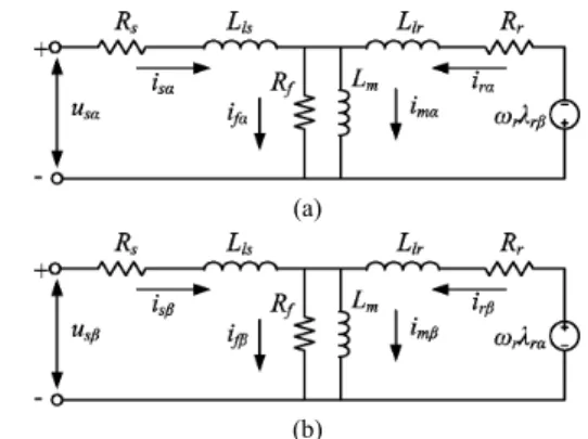
Fig. 1 shows the model of induction motor considering iron loss in the stationary α-β reference, where the α-axis aligns with the direction of phase A, and the β-axis is π/2 ahead of it.
The iron loss is represented by the iron loss resistance Rf which is connected in parallel with the magnetizing inductance.
(a)
(b)
Figure 1. Model of induction motor with iron loss. (a) α-axis. (b) β-axis.
Firstly, the voltage equations are given by
α α
α s s λs
s Ri p
u = + (1)
β β
β ss λs
s Ri p
u = + (2)
β α α λr ωrλr
r
ri p
R + +
=
0 (3)
α β β λr ωrλr
r
ri p
R + −
=
0 (4)
where us, is, Rs and λs are the stator voltage, current, resistance and flux linkage, respectively, ir, Rr, λr and ωr are the rotor current, resistance, flux linkage and rotational speed, respectively, p is the differential operator, and α and β represent the α-axis and β-axis components, respectively.
Secondly, the flux linkage equations are expressed as
α α
α λ
λs =Llsis + m (5)
β β
β λ
λs =Llsis + m (6)
α α
α λ
λr =Llrir + m (7)
β β
β λ
λr =Llrir + m (8)
α
λmα =Lmim (9)
β
λmβ =Lmim (10) where Lls is the stator linkage inductance, Llr is the rotor linkage inductance, and Lm is the magnetizing inductance.
Thirdly, the current equations are expressed as
α α α
α s r f
m i i i
i = + − (11)
β β β
β s r f
m i i i
i = + − (12) where im is the magnetizing current, and if is so-called the iron loss current. Consequently, the torque is given by
( ) ( )
[
λsα sβ λsβsα λmα fβ λmβ fα]
p
em n i i i i
T = − − −
2
3 (13)
III. POWER LOSSES MINIMIZATION
A. Estimation of power losses
Since the leakage inductances Lls and Llr are much smaller than the magnetizing inductance Lm, both Lls and Llr are negligible. Thus, the iron loss currents can be expressed as
f s s f
s
f R R
iα = pλα =−ωλβ (14)
f s s f s
f R R
iβ pλβ ωλα
=
= (15) So, the iron loss is given by
( )
f s s f f f
iron i i R R
P
2 2 2
2 ω λ
β
α+ =
= (16) where λs is the magnitude of the stator flux linkage. From (3)- (4) and (11)-(12), it yields
( )
r s r s r
r r r
r R R
iα pλα ω λβ ω −ω λβ + =
−
= (17)
( )
r s s r r
r r r
r R R
iβ pλβ ωλα ω −ω λα
− =
−
= (18)
α β α α α
α λ ω ω ω λ
s r
r s f s m s r f m
s i i i L R R
i ⎟⎟
⎠
⎞
⎜⎜
⎝
⎛ −
+
−
=
− +
= (19)
α β
β β β
β λ ω ω ω λ
s r
r s f s m s r f m
s i i i L R R
i ⎟⎟
⎠
⎞
⎜⎜
⎝
⎛ −
+ +
=
− +
= (20)
where ωs is the rotational speed of the stator flux linkage. Thus, the copper losses occurred in the stator and the rotor are given by
( )
( )r s r s r r r
cur i i R R
P
2 2 2
2 ω ω λ
β α
= − +
= (21)
(
2 2)
12 2 s s2r r s f s m s s s
cus R
R R R L
i i
P ω ω ω λ
β
α ⎥⎥
⎦
⎤
⎢⎢
⎣
⎡
⎟⎟
⎠
⎞
⎜⎜
⎝
⎛ + −
+
= +
= (22)
Consequently, the total power losses can be expressed as
( )
f s s r
s r s s s r
r s f s m
cur cus iron loss
R R R
R R L
P P P P
2 2 2 2
2 2 2
1 ω ω ω λ + ω −ω λ +ω λ
⎥⎥
⎦
⎤
⎢⎢
⎣
⎡
⎟⎟
⎠
⎞
⎜⎜
⎝
⎛ + −
+
=
+ +
=
(23)
B. Minimization of power losses
When ignoring the leakage inductances, from (13)-(15) and (19)-(20), the electromagnetic torque becomes
( ) r
s r p
em s R
s T n
= − 1 2
3 ω λ 2 (24) where s=(ωs−ωr)ωs is the slip. Thus, it yields
( )
r p
em r
s n s
T R s λ ω
3 1 2
2 = − (25) Substituting (25) into (23), it gets
( ) ( )
( )
( )
( )
( ) ⎥⎥
⎥⎥
⎥
⎦
⎤
⎢⎢
⎢⎢
⎢
⎣
⎡
− + + +
− + +
−
=
f r
r r s f r s
f r r f s m r
s r
p em loss
R R s
R R R R R s
R s s
R R R L s
R R s n P T
1 2 1 1
3
2 2 2
ω ω
ω (26)
Since the working point (ωr, Tem) of the motor drive is governed by requirements of the work load, the total power loss can be minimized when it satisfies
=0
∂
∂ s
Ploss (27) Thus, the optimal slip so can be obtained as
( ) ( ) ( ( ) ( )) ( ) ( )( ) ( ) ( )r r
r r r r r
r
so
ω ω
ω ω ω ω ω
ω
Λ + Γ
Λ + Π Γ
− Π + Π
−
=Γ (28)
( ) 2
m r
s r
r L
R R ω =−ω
Γ (29)
( ) ( )
2 f
r r s f
r R
R R
R ω
ω = +
Π (30)
( ) (( ) )
f r
r r s f r s
r RR
R R R R
R ω
ω = + +2
Λ (31) Moreover, from (25), the optimal stator flux linkage can be obtained as:
( )( )
( )
( )
( )( )
( )
( )
2 1 2 1
2 1
3 2
⎥⎥
⎦
⎤
⎢⎢
⎣
⎡
Λ + Π Γ
− Π + Π
− Γ
Λ + Π Γ
− Π
− Π +
= Λ
r p
em r
so n
T R
λ ω (32)
For an induction motor with the parameters given in the Appendix, the optimal stator flux linkage and the optimal efficiency corresponding to different working point are illustrated in Fig. 2. It can be seen that the optimal stator flux linkage is more sensitive to the output torque than to the rotational speed. Moreover, by choosing the optimal stator flux linkage, the efficiency can be significantly improved, especially for the operating region with low output torque and middle to high rotational speed, where the efficiency can reach higher than 85 %. While, it is known that the efficiency of induction motor with light loads under traditional control strategies are less than 40 %.
(a)
(b)
Figure 2. (a) Optimal stator flux linkage. (b) Resulted efficiency.
(a) (b)
(c) (d)
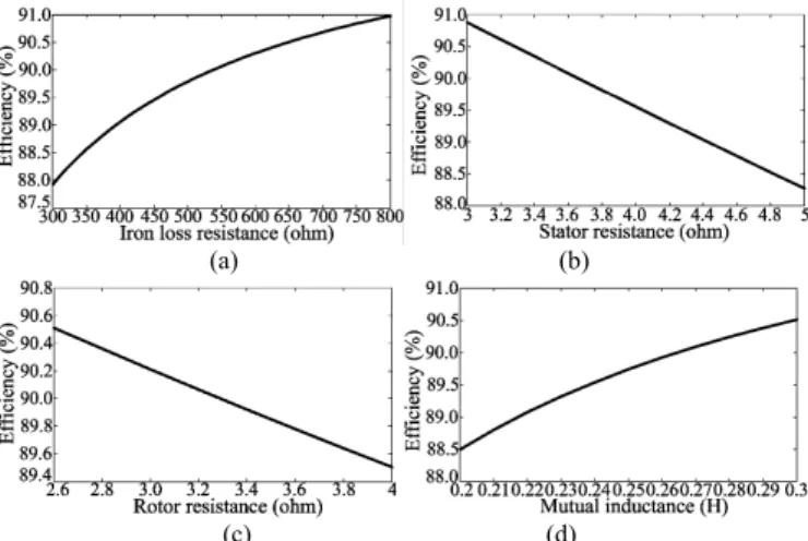
Figure 3. Parameter sensitivity. (a) Iron loss resistance. (b) Stator resistance.
(c) Rotor resistance. (d) Mutual inductance.
C. Parameter sensitivity
From (30)-(32), it can be known that the optimal stator flux linkage is dependent to the rotational speed and the output torque as well as the motor parameters, such as the stator resistance Rs, the rotor resistance Rr, the iron loss resistance Rf
and the mutual inductance Lm. However, these parameters may fluctuate with the temperature of the windings and the saturation of the magnetic paths. In order to figure out the parameter sensitivity of the proposed power loss minimization algorithm, Fig. 3 gives the curves of the optimal efficiency
versus each parameter. The corresponding working point is chosen as ωr= 160 rad/s, Tem=0.5 Nm. It can be found that, the fluctuations of the motor parameters have a trivial influence on the resulted efficiency.
IV. EFFICIENCY-OPTIMIZED SVMDTC
Fig. 4 shows the proposed efficiency-optimized SVM DTC scheme for the induction motor. The control algorithm consists of eight parts: 3/2 reference transform, stator flux observer, electromagnetic torque observer, PI speed adjuster, PI torque adjuster, optimum efficiency unit (OEU), voltage vector estimator and SVM unit. The 3-phase rectifier and inverter system can supply 8 voltage vectors to the motor, in which, only 6 are effective voltages, and the other two are zero voltages. In the traditional DTC, the needed voltage is chosen by a switching table and two hysteresis compactors during any sample period. Then the stator flux linkage and the electromagnetic torque are controlled to be their referenced values. The stator flux linkage can be estimated by
∫ −
= t s s s
s u i R dt
0( α α )
λα (33)
∫ −
= t s s s
s u i R dt
0( β β )
λβ (34)
2 2α λβ
λ
λs = s + s (35) For simplicity, the effect of the iron loss on the developed electromagnetic torque is ignored. Thus, from (13), it yields
(λsα sβ λsβ sα)
p
em n i i
T = −
2
3 (36) Since the number of the usable effective voltage vectors is quite limited, the traditional DTC suffers from the drawbacks of non-constant switching frequency and large torque and speed ripples. Herein, the SVM method is adopted to supersede the fixed switching table and the hysteresis compactors. Firstly, it is well known that the developed electromagnetic torque Tem
is strongly related to the incremental angle δ of the stator flux linkage vector during each sampling period, namely, positive value of δ means positive Tem, big value of δ implies big Tem, and vice versa. Thus, as shown in Fig. 4, a PI torque adjuster is engaged to decide the expectation value of δ in the present sampling period. It is noteworthy that in order to ensure the stability of the control algorithm, a limiter should be involved in the torque adjuster, and the limited value can be determined according to the expectative maximum speed ωrmax by
s r
p T
n ωmax
χ= (37) where Ts is the sampling period. Secondly, as shown in Fig.
5(a), the expectative voltage vector can be estimated by
( ) ( )
( sk sk sk sk )
s k
s T
uα 1 λ cosθ δ λ cosθ
) 1 ( )
1
(+ = + ⋅ + − ⋅ (38)
( ) ( )
( sk sk sk sk )
s k
s T
uβ 1 λ sinθ δ λ sinθ
) 1 ( )
1
(+ = + ⋅ + − ⋅ (39)
Thirdly, the expectative voltage vector is synthesized by the existing 8 voltage vectors supplied by the inverter. As shown in Fig. 5(b), assuming that the us(k+1)lies in the
[
0o−60o]
zone, voltages u1, u2, u0 and u7 are engaged to form us(k+1). Thesymmetrical switching pattern in Fig. 5(c) is used to minimize the switching loss, and the switching times can be obtained by
( )
dc k s k
s s
u u u
T T
2 3 3 ( 1) ( 1)
1
+
+ −
= α β (40)
dc k s s
u u T2 3T (+1)
= β (41)
( 1 2)
7
0 2
1 T T T T
T = = s− − (42)
where udc is the dc bus voltage of the inverter.
Moreover, in order to achieve minimized power loss operation, the flux linkage reference is no longer kept as its rated value but online updated according to the instantaneous load torque and rotational speed given by (32). Thus, the overall efficiency can be dramatically improved, especially for the light-load case. For safety precaution, the OEU should be governed by the maximum current constraint:
Figure 4. Proposed efficiency-optimized SVM DTC scheme.
(a) (b) (c)
Figure 5. Space vector modulation. (a) Voltage vector estimation. (b) Synthesis of voltage vector. (c) Symmetrical switching.
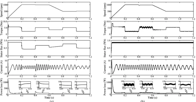
(a) (b)
Figure 6. Simulation results. From top: Speed curve, electromagnetic torque curve, stator flux linkage curve, stator current curve (α-component) and power loss curve. (a) Proposed high efficiency SVM DTC. (b) Traditional DTC.
Imax
is < (43) Once the resulted current magnitude goes over its safety limit, the flux linkage reference should be switched to its rated value. In addition, the power loss minimization algorithm should not be put into operation during the start-up process.
From (32), the calculated optimal flux value is relatively small when the rotational speed is low which may result in start-up failure since a high torque is generally needed for start-up.
V. SIMULATION RESULTS
Simulation study is conducted by using the MATLAB Simulink software. Fig. 6 shows the simulation results of the comparison between the proposed high efficiency SVM DTC and the traditional DTC. For fair assessment, the PI parameters of the speed adjuster in both control methods are the same. The speed reference is given as: the motor speed goes up to 1000 rpm from 0 rpm with constant acceleration value in the first 0.2 s; then it is kept as 1000 rpm in the next 0.4 s; during 0.6 s to 0.8 s, it evenly decelerates to 500 rpm; and it is kept unchanged in the last 0.4 s. The load torque is kept as 2 Nm during 0 s to 0.4 s and 1.0 s to 1.2 s, and changed into 5 Nm during 0.4 s to 0.8 s. In the traditional DTC, the stator flux linkage reference is set as 0.85 Wb all the time, while in the proposed algorithm, the system is switched into high efficiency mode at 0.2 s, and the stator flux linkage reference is online updated by the OEU.
It can be found that both control methods exhibit good dynamic performance. While, the torque ripple in the proposed method is dramatically reduced by using the SVM. Moreover, the power loss in the proposed method is also reduced in the stable phases by adjusting the stator flux linkage.
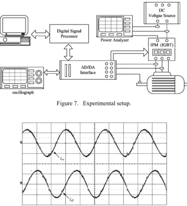
Figure 7. Experimental setup.
Figure 8. Measured stator currents (100ms/div, 2v/div).
VI. EXPERIMENTAL RESULTS
Fig. 7 illustrates the experimental setup of the induction motor drive system. The IGBT module is fed by a dc voltage source to form an inverter, and then supply power to the induction motor. The proposed control algorithm is realized by a digital signal processor (DSP), and the sampling frequency is 10 kHz. A power analyzer is connected to the dc bus of the inverter to measure the input power of the system. Fig. 8 gives the measured stator current with ωr=1000 rpm, TL=2 Nm. By deducting the output mechanical power from the input electric power measured in the dc bus side, Fig. 9 gives the power loss with different working loads. The power loss with fixed stator flux reference λs=0.85 Wb is also given for comparison. It can be found that the power loss is successfully reduced by adjusting the stator flux reference, especially when the motor with light loads.
In order to assess the dynamic performance of the proposed control algorithm, the speed reference is set as: from 0 s to 2 s, the speed goes up to 1000 rpm with constant acceleration value;
from 2 s to 6 s, the speed is kept as 1000 rpm; from 6 s to 8 s, the speed evenly decelerates to 0 rpm. In the whole process, the load torque is kept as 4 Nm. Fig. 10 gives the measured real speed, electromagnetic torque, stator flux and stator current. It can be seen that the real speed agrees well with its aim value.
Moreover, the torque ripple is very little due to the adoption of the SVM. The stator flux linkage is no longer kept as a constant but online updated according to the instantaneous working point of the motor.
Figure 9. Power loss with different working loads.
Figure 10. Dynamic performance. From top: Speed curve, electromagnetic torque curve, stator flux curve, α-axial stator current curve. (2000 rpm/div, 5
Nm/div, 1 Wb/div, 5 A/div, 1 s/ div).
VII. CONCLUSIONS
In this paper, a new efficiency-optimized space-vector- modulation direct torque control scheme is proposed and implemented for induction motor drives. Since the stator flux linkage reference is online updated by the optimal efficiency unit according to the instantaneous working point, the proposed control method can achieve minimized power loss operation.
Moreover, the torque ripples can be significantly reduced by adopting space vector modulation. Both simulation and experimental results verify the validity of the proposed control algorithm.
APPENDIX
Induction motor parameters:
Rs=3.5 Ω, Rr=3 Ω, Rf=580 Ω,
Lls=0.040 H, Llr=0.015 H, Lm =0.278 H, p=2, J=0.00665 kgm-2, B=0.00532 Nm/rad/s
REFERENCES
[1] B. Mirafzal, G. Skibinski and R. Tallam, “Determination of parameters in the universal induction motor model,” IEEE Trans. Ind. Appl., vol. 45, no. 1, pp. 142-151, Jan./Feb. 2009.
[2] S. Z. Jiang, K. T. Chau and C. C. Chan, “Performance analysis of a new dual-inverter pole-changing induction motor drive for electric vehicles,”
Electric Power Components and Systems, vol. 30, no.1, pp. 11-29, Jan.
2002.
[3] S. Z. Jiang, K. T. Chau and C. C. Chan, “Spectral analysis of a new six- phase pole-changing induction motor drive for electric vehicles,” IEEE Trans. Ind. Electron., vol. 50, no. 1, pp. 123-131, Feb. 2003.
[4] R. Krishnan, Switched Reluctance Motor Drives: Modeling, Simulation, Analysis, Design and Applications. Boca Raton: CRC Press, 2001.
[5] J. H. Chen, K. T. Chau, C. C. Chan and Q. Jiang, “Subharmonics and chaos in switched reluctance motor drives,” IEEE Transactions on Energy Conversion, vol. 17, no. 1, pp. 73-78, Mar. 2002.
[6] K. T. Chau and J. H. Chen, “Modeling, analysis and experimentation of chaos in a switched reluctance drive system,” IEEE Transactions on Circuits and Systems - I: Fundamental Theory and Applications, vol. 50, no. 5, pp. 712-716, May 2003.
[7] C. C. Chan and K. T. Chau, “An advanced permanent magnet motor drive system for battery-powered electric vehicles,” IEEE Transactions on Vehicular Technology, vol. 45, no. 1, pp. 180-188, Feb. 1996.
[8] C. C. Chan, K. T. Chau, J. Z. Jiang, W. Xia, M. Zhu and R. Zhang,
“Novel permanent magnet motor drives for electric vehicles,” IEEE Transactions on Industrial Electronics, vol. 43, no. 2, pp. 331-339, April 1996.
[9] K. T. Chau, W. Cui, J. Z. Jiang and Z. Wang, “Design of permanent magnet brushless motors with asymmetric air gap for electric vehicles,”
Journal of Applied Physics, vol. 99, no. 8, paper no. 80R322, pp. 1-3, Apr. 2006.
[10] C. C. Chan, J. Z. Jiang, G. H. Chen, X. Y. Wang and K. T. Chau, “A novel polyphase multipole square-wave permanent magnet motor drive for electric vehicles,” IEEE Trans. Ind. Appl., vol. 30, no. 5, pp. 1258- 1266, Sep. 1994.
[11] J. Gan, K. T. Chau, C. C. Chan and J. Z. Jiang, “A new surface-inset, permanent-magnet, brushless DC motor drive for electric vehicles,”
IEEE Transactions on Magnetics, vol. 36, no. 5, pp. 3810-3818, Sep.
2000
[12] L. Jian, K. T. Chau and J. Z. Jiang, “A magnetic-geared outer-rotor permanent-magnet brushless machine for wind power generation,” IEEE Trans. Ind. Appl., vol. 45, no. 3, pp. 954-962, May/June 2009.
[13] Y. Liao, F. Liang, and T. A. Lipo, “A novel permanent motor with doubly salient structure,” IEEE Trans. Ind. Appl., vol. 31, no. 5, pp.
1069-1078, Sep./Oct. 1995.
[14] K. T. Chau, M. Cheng and C. C. Chan, “Nonlinear magnetic circuit analysis for a novel stator-doubly-fed doubly-salient machine,” IEEE Transactions on Magnetics, vol. 38, no. 5, pp. 2382-2384, Sep. 2002.
[15] M. Cheng, K. T. Chau and C. C. Chan, “New split-winding doubly salient permanent magnet motor drive,” IEEE Transactions on Aerospace and Electronic Systems, vol. 39, no. 1, pp. 202-210, Jan. 2003.
[16] S. Niu, K. T. Chau, J. Z. Jiang and C. Liu, “Design and control of a new double-stator cup-rotor permanent-magnet machine for wind power generation,” IEEE Transactions on Magnetics, vol. 43, no. 6, pp. 2501- 2503, Jun. 2007.
[17] K. T. Chau, Y. B. Li, J. Z. Jiang and S. Niu, “Design and control of a PM brushless hybrid generator for wind power application,” IEEE Transactions on Magnetics, vol. 42, no. 10, pp. 3497-3499, Oct. 2006.
[18] C. Liu, K. T. Chau, J. Z. Jiang and L. Jian, “Design of a new outer-rotor permanent magnet hybrid machine for wind power generation,” IEEE Transactions on Magnetics, vol. 44, no. 6, pp. 1494-1497, Jun. 2008.
[19] K. T. Chau, C. C. Chan and C. Liu, “Overview of permanent-magnet brushless drives for electric and hybrid electric vehicles,” IEEE Transactions on Industrial Electronics, vol. 55, no. 6, pp. 2246-2257, Jun. 2008.
[20] V. Ostovic, “Memory motors - a new class of controllable-flux permanent magnet machines for true wide-speed operation,” IEEE Ind.
Appl. Mag., vol. 9, no. 1, pp. 52-61, Jan./Feb. 2003.
[21] C. Yu, K. T. Chau, and J. Z. Jiang, “A flux-mnemonic permanent magnet brushless machine for wind power generation,” J. Appl. Phys., vol. 105, no. 7, paper no. 07F114, pp. 1-3, Apr. 2009.
[22] K. T. Chau and C. C. Chan, “Emerging energy-efficient technologies for hybrid electric vehicles,” Proceedings of IEEE, vol. 95, no. 4, pp. 821- 835, Apr. 2007.
[23] G. Dong and O. Ojo, “Efficiency optimizing control of induction motor using natural variables,” IEEE Trans. Ind. Electron., vol. 53, no. 6, pp.
1791-1798, Dec. 2006.
[24] M. N. Uddin and S. W. Nam, “New online loss-minimization-based control of an induction motor drive,” IEEE Trans. Power Electron., vol.
23, no. 2, pp. 926-933, Mar. 2008.
[25] S. K. Sul and M. H. Park, “A novel technique for optimal efficiency control of a current-source inverter-fed induction motor,” IEEE Trans.
Power Electron., vol. 3, no. 2, pp. 192-199, Apri. 1998.
[26] J. Jung and K. Nam, “A vector control scheme for EV induction motors with a series iron loss model,” IEEE Trans. Ind. Electron., vol. 45, no. 4, pp. 617–642, Aug. 1998.
[27] C. Charkraborty and Y. Hori, “Fast efficiency optimization techniques for the indirect vector-controlled induction motor drives,” IEEE Trans.
Ind. Appl., vol. 39, no. 4, pp. 1070-1076, Jul./Aug. 2003.
[28] G. S. Buja and M. P. Kazmierkowski, “Direct torque control of PWM inverter-fed ac motors-a survey,” IEEE Trans. Ind. Electron., vol. 51, no.
4, pp. 744-757, Aug. 2004.
[29] Y. Lai and J. Chen, “A new approach to direct torque control of induction motor drives for constant inverter switching frequency and torque ripple reduction,” IEEE Trans. Energy Conv., vol. 16, no. 3, pp.
220-227, Sep. 2001.
[30] Y. Lai, W. Wang and Y. Chen, “Novel switching techniques for reducing the speed ripple of ac drive with direct torque control,” IEEE Trans. Ind. Electron., vol. 51, no. 4, pp. 768-775, Aug. 2004.
[31] N. R. N. Idris, C. L. Toh and M. E. Elbuluk, “A new torque and flux controller for direct torque control of induction machines,” IEEE Trans.
Ind. Appl., vol. 42, no. 6, pp. 1358-1366, Nov./Dec. 2006.
[32] D. Casadei, G. Serra and A. Tani, “Implementation of a direct torque control algorithm for induction motors based on discrete space vector modulation,” IEEE Trans. Power Electron., vol. 15, no. 4, pp. 769-777, Jul. 2000.