Level C+ Data Reuse Scheme for Motion Estimation With Corresponding
Coding Orders
Ching-Yeh Chen
,Chao-Tsung Huang
,Yi-Hau Chen
, andLiang-Gee Chen, Fellow, IEEE
Abstract—The memory bandwidth reduction for motion
es-timation is important because of the power consumption and limited memory bandwidth in video coding systems. In this paper, we propose a Level C+ scheme which can fully reuse the over-lapped searching region in the horizontal direction and partially reuse the overlapped searching region in the vertical direction to save more memory bandwidth compared to the Level C scheme. However, direct implementation of the Level C+ scheme may conflict with some important coding tools and then induces a lower hardware efficiency of video coding systems. Therefore, we propose -stitched zigzag scan for the Level C+ scheme and discuss two types of 2-stitched zigzag scan for MPEG-4 and H.264 as examples. They can reduce memory bandwidth and solve the conflictions. When the specification is HDTV 720p, where the searching range is [ 128,128), the required memory bandwidth is only 54%, and the increase of on-chip memory size is only 12% compared to those of traditional Level C data reuse scheme.
Index Terms—Data reuse, memory bandwidth, motion
estima-tion.
I. INTRODUCTION
M
ULTIMEDIA applications are more and more popularas the technologies of image sensor, communication, VLSI manufacture, and video coding are made great progress. Among various multimedia applications, video applications are always attractive, but the required transmission bandwidth and the storage size of video are also much larger than others. Many video coding standards, such as MPEG series [2]–[4] and H.264/AVC [5], are established to compress video data in order to save the required transmission bandwidth or the storage size. However, large computation resources and huge memory bandwidth are necessary to perform the video compression.
Motion estimation (ME) is the major component of a video coding system, and it also dominates the greater part of com-putation complexity and memory bandwidth in a video coding system. The large computation complexity is due to a lot of can-didate blocks to be matched, and the huge memory bandwidth results from loading the data of candidate blocks. The large computation complexity can be solved by a hardware acceler-ator with highly parallel computation. However, the resource of memory bandwidth is limited in a video coding system, and
Manuscript received May 23, 2005; revised August 23, 2005. This work is an extension in part of [1], which was presented at the International Conference on Acoustic, Speech, and Signal Processing 2005. This paper was recommended by Associate Editor I. Ahmad.
The authors are with the Graduate Institute of Electronics Engineering, De-partment of Electrical Engineering, National Taiwan University, Taipei 106, Taiwan, R.O.C. (e-mail: [email protected]; [email protected]. edu.tw; [email protected]; [email protected]).
Digital Object Identifier 10.1109/TCSVT.2006.871388
huge memory bandwidth also induces a large power consump-tion of system bus. How to reduce the memory bandwidth is an important issue of hardware design. Hence, in [6] and [7], four levels of searching region data reuse from Level A to Level D are discussed for hardware accelerators, which are designed for full search block matching algorithms (FSBMA) and load the whole searching range data to compute. Among four levels, Level C scheme which can fully reuse the overlapped searching region between two successive macroblocks (MBs) in the horizontal direction is usually adopted because of the tradeoff between the reduction of memory bandwidth and the required on-chip memory size.
Even if the Level C scheme has been applied, the required memory bandwidth of loading the data of candidate blocks is still huge, especially for a large searching region or
high-res-olution videos. For example, in HDTV 1280 720 with
30 frames per second (fps), if the searching range is [ 128, 128) in both directions, the required memory bandwidth with Level C scheme is still large, 536 MBytes/s. Therefore, the Level C data reuse scheme is not enough. In this paper, we propose a Level C+ scheme [1] which not only can fully reuse the overlapped searching region in the horizontal direction, but can also partially reuse the overlapped searching region in the vertical direction when the entire searching range data are loaded. Then, the Level C+ scheme is capable of saving much more memory bandwidth with a little overhead of on-chip memory size.
Although the Level C+ scheme can save more memory bandwidth than the Level C scheme, the direct implementa-tion of the Level C+ scheme conflicts with some important video coding tools, such as motion vector (MV) prediction and Lagrangian mode decision, and will lower the hardware utilization of video coding systems. Hence, we also propose
the corresponding coding order, -stitched zigzag scan, for
the Level C+ scheme and discuss two 2-stitched zigzag scans for different video coding systems with different architectures as examples. Finally, two case studies are given to show the tradeoff between on-chip memory size and external memory bandwidth.
The structure of this paper is as follows. In Section II, the four level and the Level C+ schemes will be introduced. Next, we propose -stitched zigzag scan for the Level C+ scheme in Section III and discuss two scan orders as examples. Two case studies of D1 and HDTV specifications are shown in Section IV, and a conclusion is given in Section V.
II. MB-LEVELDATAREUSE FORME
Among various ME algorithms, the block matching algorithm (BMA), which is used to find the best matched candidate block from the searching range in the reference frame for every block
554 IEEE TRANSACTIONS ON CIRCUITS AND SYSTEMS FOR VIDEO TECHNOLOGY, VOL. 16, NO. 4, APRIL 2006
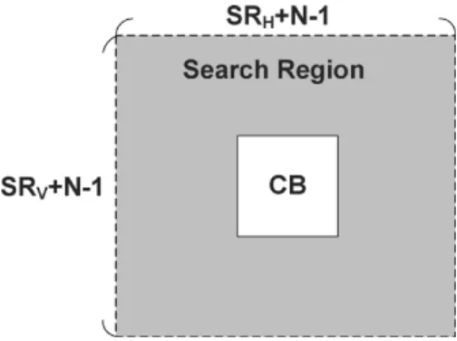
Fig. 1. Current MB (CB) and searching region for BMA, whereSR = 2P andSR = 2P .
in the current frame (current MB), is the most commonly used. The matching criteria is usually the sum of absolute differences
(SAD). If the searching range is in the horizontal
direction and in the vertical direction, the current
MB of size and the corresponding searching region are
shown in Fig. 1, where and . The
FSBMA is to search every candidate block in the searching re-gion, and the fast BMA, such as three-step search [8], diamond search [9], [10], and so on, is trying to search much fewer candi-date blocks than FSBMA without too much quality degradation. In this paper, we only discuss the general data reuse schemes of the searching region. Obviously, the FSBMA needs to load the whole searching region for every current MB. The fast BMA can also load the whole searching region or only load the selected candidate blocks. However, the external memory bandwidth of the latter depends on the searching pattern of candidate blocks in the adopted fast BMA algorithm and could be larger than the former which is the same as FSBMA. In the following, the data reuse schemes of FSBMA are reviewed, and a new scheme, the Level C+ scheme, will be proposed.
More-over, we assume that the size of current MB is , and the
searching range is to discuss the performances.
A. Conventional Data Reuse Schemes for FSBMA
In [6] and [7], four data reuse levels from Level A to Level D are discussed for the data reuse of successive candidate blocks or current MBs. Two factors can be used to evaluate the per-formance of data reuse schemes: on-chip memory size for the
reference frame and redundancy access factor . The on-chip
memory size represents the required memory size to buffer the
data of candidate blocks for data reuse. is used to evaluate
the external memory bandwidth and defined as
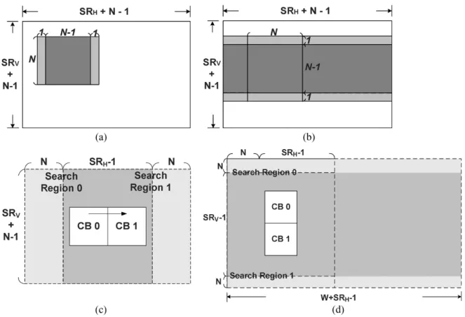
Total memory bandwidth for reference frame Minimum memory bandwidth (pixel count in total) Fig. 2 shows the four data reuse schemes from Level A to Level D. Level A and Level B schemes represent the searching region data reuse between successive candidate blocks for one
current MB. Level A only reuses the overlapped
pixels between two successive candidate blocks in the hori-zontal direction, as shown in Fig. 2(a). Level B can reuse the overlapped pixels between candidate blocks not only in the hor-izontal direction but also in the vertical direction, as shown in
Fig. 2(b). Compared to Level A and B, Level C and Level D schemes represent the searching region data reuse between suc-cessive current MBs. The Level C scheme is often used thanks to the current memory technology, and it can reuse the hori-zontal overlapped region between two searching regions of two neighboring current MBs, as shown in Fig. 2(c) where only pixels are required to be loaded from
ex-ternal memory for every current MB. Thus, the of the Level
C scheme can be calculated as
(1) The required on-chip memory size for the reference frame in the Level C scheme depends on the detailed implementation of ME architectures. We assume that it is one searching region
size , such that motion
com-pensation can be performed immediately after ME without any other external memory access. As for the Level D scheme, it can minimize the memory access by fully reusing the horizon-tally and vertically overlapped searching regions with a huge
local memory size, where is the
image width, as shown in Fig. 2(d).
B. Proposed Level C+ Scheme for FSBMA
By the extension of raster scan, we propose a Level C+ scheme with stripe scan. By using stripe scan, not only can the overlapped searching region in the horizontal direction be fully reused, but also the overlapped searching region in the vertical direction can be partially reused, as shown in Fig. 3. That is, several successive current MBs in the vertical direction are stitched, and the searching region of these current MBs is loaded, simultaneously. Therefore, if vertical current MBs are stitched, which is called -stitched, only
pixels are required to be loaded from external memory for
every successive vertical current MBs. Then, the of the
proposed Level C+ scheme is
(2) Compared to the Level C scheme, the ratio of memory bandwidth is
(3) and the ratio of required on-chip memory sizes is
. Therefore, if is much larger than ,
then the ratio of memory bandwidth will be near to , and the
overhead of on-chip memory is small.
We summarize the performances of Level C, Level D, and our proposed Level C+ schemes in Table I. As shown in Table I, the proposed Level C+ scheme can provide much more combina-tions of memory bandwidth and on-chip memory size between
the Level C and D schemes. The larger the is, the less the
Fig. 2. Schemes of searching range data reuse for FSBMA, where the heavy gray region is the overlapped and reused region. (a) Level A. (b) Level B. (c) Level C. (d) Level D.
Fig. 3. Scheme of proposed Level C+ searching region data reuse for FSBMA, where the heavy gray region is the overlapped and reused regionn = 2.
Level C+ scheme will be when is fixed. When a large is
se-lected, the reduction ratio of memory bandwidth is also larger, but the overhead of on-chip memory is also increased.
III. PROPOSED -STITCHEDZIGZAGSCAN
Although the Level C+ scheme can save more external memory bandwidth with the less overhead of on-chip memory size, the Level C+ scheme with stripe scan conflicts with some coding tools such as Lagrangian mode decision and MV predictor. This is because, in general, the side information of left, top, and top-right MBs are necessary to encode current MBs, as shown in Fig. 4. The raster scan can satisfy these data dependencies, but the direct implementation of stripe scan
TABLE I
COMPARISON OFDIFFERENTDATAREUSESCHEMES FORME
Fig. 4. Required side information for Lagrangian mode decision or MV pre-dictor.
cannot. Therefore, the direct implementation of the Level C+ scheme with strip scan could lower the hardware efficiency of video coding systems with these functions and architectures.
In the previous works with raster scan, the data dependency of the left MB may not be satisfied, if there is a deep MB-pipelining architecture, where several current MBs are processed simulta-neously in different functional modules. Therefore, the data de-pendency of the left MB is carefully designed to satisfy the side information in time in an MB-pipelining architecture. Hence,
556 IEEE TRANSACTIONS ON CIRCUITS AND SYSTEMS FOR VIDEO TECHNOLOGY, VOL. 16, NO. 4, APRIL 2006
Fig. 5. MPEG-4 encoder with two-stage MB-pipeline.
the hardware efficiency is high, and the required data buffer is small.
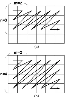
Compared to raster scan, satisfying the data dependency of the left MB is much easier in the stripe scan because there are some other MBs which are processed between the computations of left MB and current MB. Therefore, the side information of left MB will be generated earlier in the stripe scan than the raster scan. However, the data dependencies of the top and top-right MBs become a problem. In order to satisfy the requirements of side information in the MB-pipelining architectures, we pro-pose the -stitched zigzag scan for the Level C+ scheme. In the -stitched zigzag scan, several successive MBs in a horizontal direction will be processed before the vertical scan starts, and MB rows are processed alternately in the vertical scan. The former can guarantee that the data dependencies of neighboring MBs are satisfied, and the latter uses the concept of the Level C+ scheme to reduce the required memory bandwidth. We called
this scan order of -stitched zigzag scan HF V , where and
are positive integers. HF V means that successive MBs
in horizontal direction are processed before the vertical scan starts, and MB rows are processed alternately in the vertical scan.
By -stitched zigzag scan, the side information will be avail-able in time, so previous architectures with the Level C+ scheme can be executed efficiently. In the following subsections, we fur-ther discuss two types of 2-stitched zigzag scan for MPEG-4 and H.264 with different ME-pipelining architectures as two
exam-ples. We still assume that the size of the current MB is ,
and the searching range is in the following
dis-cussion.
A. Proposed HF2V2 for MPEG-4
Fig. 5 shows the architecture of an MPEG-4 encoder with two-stage MB-pipeline [11], [12]. The first stage is the ME en-gine, and the second is the block engine (BE) which consists of motion compensation (MC), discrete cosine transform (DCT), quantization (Q), inverse quantization (IQ), inverse discrete co-sine transform (IDCT), and entropy coding (EC). Because of two-stage MB-pipeline, two MBs are processed at the same time. That is, if current MB is in the ME engine, the left MB is in the BE engine. In this architecture, the side information includes MV predictor, DC/AC coefficients of DCT transform, and so on, in the second stage. Because of MV predictor, which is the medium among the MVs of the left, top, and top-right MBs, as shown in Fig. 4, the top-right MB has to be coded before cur-rent MB. But in the stripe scan, the top-right MB is coded after the current MB and then the Level C+ scheme with stripe scan cannot be directly applied.
Fig. 6. Proposed HF2V2 scan for MPEG-4 with two-stage MB-pipeline.
We propose a HF2V2 scan, which is one of 2-stitched zigzag scans, to satisfy the requirement of side information in the MPEG-4 encoder witha two-stage MB-pipeline. HF2V2 means that the horizontal scan is executed first and followed by the vertical scan. In the horizontal scan, the first two
MBs in the upper MB row are processed, and in the vertical
scan, two successive vertical MB rows are stitched
and the MBs in these two MB rows are processed alternatively, as shown in Fig. 6. In the proposed HF2V2 scan, because two MBs in the upper MB row are processed first, the top-right MB will be processed before current MB and then the requirement of the MV predictor is satisfied.
By using the Level C+ scheme with an HF2V2 scan, and two
successive vertical MB rows are stitched, the memory
bandwidth is approximately half compared to that of the Level C scheme with raster scan. The on-chip memory size is increased
from to
. If and are much larger than
, the overhead of on-chip memory size is small. Note that the required on-chip memory size is larger than that of the Level C+
scheme with stripe scan , as shown in Table I. This is
because the horizontal scan is processed first to satisfy the data dependency.
B. Proposed HF3V2 for H.264
Because of multiple reference frames in H.264, the memory bandwidth of ME is much larger and becomes more critical than
that in previous standards, For example, if there are
refer-ence frames, and the searching ranges in the different referrefer-ence
frames are the same, the memory bandwidth is times of that
in one reference frame. Hence, an efficient data reuse scheme of searching region for ME is much required.
Because a two-stage MB-pipeline is not suitable for H.264, four-stage MB-pipeline is proposed in [13]. The four-stage MB-pipeline, as shown in Fig. 7, consists of integer ME (IME), fractional ME (FME), intra-prediction and DCT/Q/IQ/IDCT (intra), in-loop deblocking filter (DB), and entropy coding (EC). The requirements of the original side information for H.264 in-clude Lagrangian mode decision [14] in IME and FME stages, intra-prediction, MV predictor in intra-stage, entropy coding in EC/DB stage, and so on. Due to the four-stage MB-pipeline with the raster scan [13], when a current MB is processed in the IME stage, the left MB is processed in the FME stage and then the side information of the left MB is not available. Therefore, the side information of the top-left MB is used instead of the left MB, as shown in Fig. 4. In this subsection, we first discuss
Fig. 7. H.264 encoder with four-stage MB-pipeline.
Fig. 8. Proposed HF3V2 scan for H.264/AVC with four-stage MB-pipeline.
how to satisfy the data dependency of [13], and then discuss another possible solution for an H.264 encoder with four-stage MB-pipeline.
We propose an HF3V2 scan for H.264 with a four-stage MB-pipeline and the Level C+ scheme, as shown in Fig. 8. The HF3V2 scan is also one type of 2-stitched zigzag scan and similar to the HF2V2 scan, except in the horizontal scan, the
first three MBs in the upper MB row are processed
instead of two MBs in the HF2V2 scan. This is
because the side information is generated in the third stage of the four-stage MB-pipeline, not in the second stage of the two-stage MB-pipeline. Hence, before the vertical scan starts, we require one more MB to be computed between the computations of top-right and current MBs to satisfy the data dependency in the first stage. The data dependency of the FME stage is satisfied easily because the left MB is processed earlier than that in the raster scan. Therefore, much more side information of the left MB can be used than the original does. By the Level C+ scheme with HF3V2 scan, the memory bandwidth is also reduced to half of that in the Level C scheme
because of . But the on-chip memory size is increased to
, which is larger than that of HF2V2 scan due to more MBs which are processed in the horizontal scan of HF3V2.
In fact, the real required side information of Lagrangian mode decision is that of the left, top, and top-right MBs. In the raster scan, the side information of the top-left MB is used instead of the left MB in the first stage because of a deep MB-pipeline. Similarly, if we can use the side information of the top-left MB to replace that of the top-right MB, the HF2V2 scan also can be applied into H.264 with a four-stage MB-pipeline and then the on-chip memory size can be reduced.
C. Extension
Moreover, we can increase in HF V scan to provide a
large reduction ratio of external memory bandwidth with the
Fig. 9. Extensions of HF2V2 scan. (a) HF2V3 scan. (b) HF2V4 scan.
Level C+ scheme. Fig. 9(a) and (b) shows the extensions of
HF2V2 scan, where HF2V3 is the case of , and HF2V4
is the case of , respectively. The larger is, the larger
the reduction ratio is, as shown in Table I. However, in order
to satisfy the data dependency, when is increased, not only
is the vertical size of on-chip memory increased, but the hori-zontal size of on-chip memory is also increased. That is, if n is increased one, the on-chip memory size in both directions are
increased . So the on-chip memory size will be increased to
, where is the
required basic horizontal size of on-chip memory when and depends on different data dependency and MB-pipelining architectures.
IV. CASESTUDIES
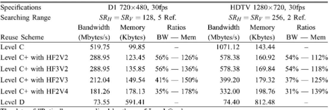
In this section, the comparison of Level C, Level D, and Level C+ schemes with different scan orders is shown in Table II. We give two case studies which are D1 and HDTV 720p specifica-tions, respectively. In D1 specification, the searching range is set as [ 64, 64) in both directions, and there are five reference frames. In HDTV 720p, there are two reference frames, and the searching range is set as [ 128, 128) in both directions.
The required external memory bandwidth of our proposed Level C+ scheme with the HF2V2 scan is only 56% in D1 Format and 54% in HDTV 720p Format compared to that of the Level C scheme. The overhead of on-chip memory size is 26% in D1 Format and 12% in HDTV 720p Format, respec-tively. From Table II, the larger the searching range is, the less the overhead of on-chip memory is. The memory bandwidth of the Level C+ scheme with the HF2V2 scan can be approx-imately 50% compared to that of the Level C scheme regardless the number of reference frames.
The memory bandwidth reduction of the HF3V2 scan is the same as that of HF2V2 scan because both of them are 2-stitched
558 IEEE TRANSACTIONS ON CIRCUITS AND SYSTEMS FOR VIDEO TECHNOLOGY, VOL. 16, NO. 4, APRIL 2006
TABLE II
COMPARISON OFDIFFERENTDATAREUSESCHEMESWITHVARIOUSSCANORDERS FORME
zigzag scan. However, the overhead of the HF3V2 scan is larger than that of HF2V2 scan. The overhead of the HF3V2 scan is 36% in D1 Format and 18% in HDTV 720p. This is because three MBs are processed first before the vertical scan starts in the HF3V2 scan instead of two MBs in the HF2V2 scan. In addition, the Level D scheme can provide the minimum memory band-width, but the on-chip memory is too large to be implemented. By contrast, the Level C+ scheme with -stitched zigzag scan can provides the significant reduction of memory bandwidth with the fewer overhead of on-chip memory.
From Table II, the HF2V3 and HF2V4 scans have more re-duction ratios of external memory bandwidth but require much more on-chip memory size. For example, by an HF2V4 scan, the external memory bandwidth can be reduced to 35% with 78% in-crease of on-chip memory size in D1 Format. Based on the results of Table II, the 2-stitched zigzag scan provides the most signifi-cant reduction of external memory bandwidth with the smallest overhead of on-chip memory size. Although the required on-chip memory size of the -stitched zigzag scan with a large is much larger, it still can reduce more memory bandwidth and can be ap-plied to special conditions, where the available memory band-width is strictly limited. Note that, for the Level C+ scheme with -stitched zigzag scan, the overhead of on-chip memory size is dependent on and the searching range, but the reduction ratio of external memory bandwidth is only dependent on , not the number of the reference frames or the searching range when the
searching range is much larger than .
V. CONCLUSION
In this paper, we propose a Level C+ scheme for the searching range data reuse of ME, which not only can fully reuse the overlapped searching region in the horizontal direction but also can partially reuse the overlapped searching region in the ver-tical direction. We also propose the corresponding coding order, -stitched zigzag scan, to realize the Level C+ scheme for real video coding systems and solve the conflictions between the Level C+ scheme and some important coding tools. Further-more, two types of 2-stitched zigzag scans for MPEG-4 and H.264 are discussed by case studies. In our proposed Level C+ scheme with HF2V2 scan, which is suitable for an MPEG-4 en-coder with two-stage MB-pipeline, external memory bandwidth can be reduced to 54% with 12% increase of on-chip memory size compared with those of the Level C scheme, if the frame size is HDTV 720p, and the searching range is [ 128, 128). As for H.264 with four-stage MB-pipeline, we also proposed an
HF3V2 scan, which can save 46% memory bandwidth with 18% overhead of on-chip memory size. Compared to the Level C and
D schemes, the Level C+ scheme with -stitched zigzag scan
can provide more different combinations of external memory bandwidth and on-chip memory size by adapting .
REFERENCES
[1] C.-T. Huang, C.-Y. Chen, Y.-H. Chen, and L.-G. Chen, “Memory anal-ysis of VLSI architecture for 5/3 and 1/3 motion-compensated temporal filtering,” in Proc. IEEE Int. Conf. Acoust., Speech, Signal Process., 2005, pp. 93–96.
[2] Information Technology—Coding of Moving Pictures and Associated
Audio for Digital Storage Media at Up to About 1.5 Mbit/s—Part 2: Video, ISO/IEC 11 172-2, 1993.
[3] Information Technology—Generic Coding of Moving Pictures and
As-sociated Audio Information: Video, ISO/IEC 13 818-2 and ITU-T Rec.
H.262, 1996.
[4] Information Technology—Coding of Audio-Visual Objects—Part 2:
Vi-sual, ISO/IEC 14 496-2, 1999.
[5] Draft ITU-T Recommendation and Final Draft International Standard
of Joint Video Specification, ITU-T Rec.H.264 and ISO/IEC 14496-10
AVC, Joint Video Team, May 2003.
[6] M.-Y. Hsu, “Scalable Module-Based Architecture for MPEG-4 BMA Motion Estimation,” M.S. thesis, National Taiwan Univ., Taipei, Taiwan, R.O.C., Jun. 2000.
[7] J.-C. Tuan, T.-S. Chang, and C.-W. Jen, “On the data reuse and memory bandwidth analysis for full-search block-matching VLSI architecture,”
IEEE Trans. Circuits Syst. Video Technol., vol. 12, no. 1, pp. 61–72,
Jan. 2002.
[8] T. Koga, K. Iinuma, A. Hirano, Y. Iijima, and T. Ishiguro, “Motion compensated interframe coding for video conferencing,” in Proc. Nat.
Telecommun. Conf., 1981, pp. G5.3.1–G5.3.5.
[9] J. Y. Tham, S. Ranganath, M. Ranganath, and A. A. Kassim, “A novel unrestricted centerbiased diamond search algorithm for block motion estimation,” IEEE Trans. Circuits Syst. Video Technol., vol. 8, no. 4, pp. 369–377, Aug. 1998.
[10] S. Zhu and K. K. Ma, “A new diamond search algorithm for fast block-matching motion estimation,” IEEE Trans. Image Process., vol. 9, no. 2, pp. 287–290, Feb. 2000.
[11] B. Koo, S. Kim, S. Lee, M. Choi, K. Park, N. Eum, J. Kim, and H. Cho, “A pipelined low power architectural MPEG4 video codec chip with deblocking filter for mobile wireless multimedia applications,” in
Proc. IEEE Int. Conf. ASIC, 2003, vol. 2, pp. 934–972.
[12] T. Nishikawa, M. Takahashi, M. Hamada, T. Takayanagi, H. Arakida, N. Machida, H. Yamamoto, T. Fujiyoshi, Y. Maisumoto, O. Yamag-ishi, T. Samata, A. Asano, T. Terazawa, K. Ohmori, J. Shirakura, Y. Watanabe, H. Nakamura, S. Minami, T. Kuroda, and T. Furuyama, “A 60 MHz 240 mW MPEG-4 video-phone LSI with 16 Mb embedded DRAM,” IEEE J. Solid-State Circuits, vol. 35, pp. 1713–1721, Nov. 2000.
[13] T.-C. Chen, Y.-W. Huang, and L.-G. Chen, “Analysis and design of macroblock pipelining for H.264/AVC VLSI architecture,” in Proc.
IEEE Int. Symp. Circuits Syst., 2004, pp. 273–276.
[14] T. Wiegand, H. Schwarz, A. Joch, F. Kossentini, and G. J. Sullivan, “Rate-constrained coder control and comparison of video coding stan-dards,” IEEE Trans. Circuits Syst. Video Technol., vol. 13, no. 7, pp. 688–703, Jul. 2003.
![Fig. 5 shows the architecture of an MPEG-4 encoder with two-stage MB-pipeline [11], [12]](https://thumb-ap.123doks.com/thumbv2/9libinfo/8855591.243622/4.891.68.429.96.232/fig-shows-architecture-mpeg-encoder-stage-mb-pipeline.webp)