行政院國家科學委員會補助專題研究計畫成果報告
※※※※※※※※※※※※※※※※※※※※※※※※※
※ ※
※
運動分解在齒輪機構拓樸分析上的應用
※
※
※
※※※※※※※※※※※※※※※※※※※※※※※※※
計畫類別:■個別型計畫
□整合型計畫
計畫編號:NSC
892212-E-002-119
執行期間:
89年
8 月
1
日至
90年
7 月
31日
計畫主持人:
陳達仁
本成果報告包括以下應繳交之附件:
□赴國外出差或研習心得報告一份
□赴大陸地區出差或研習心得報告一份
□出席國際學術會議心得報告及發表之論文各一份
□國際合作研究計畫國外研究報告書一份
執行單位:
國立台灣大學機械系
中
華
民
國
90 年
9 月
5 日
運動分解在齒輪機構拓樸分析上的應用
An Application of Kinematic Fr actionation to the Topological Analysis of
Gear ed Mechanisms
計劃編號:NSC892212-E-002-119 執行期間:八十九年八月一日至九十年七月三十一日 主持人:陳達仁,國立台灣大學機械系教授 計畫參與人員:劉佳斌、白維銘、張育宗 摘要 本研究利用運動分解的概念, 建立齒輪機構的系統化拓 樸分析方法. 將齒輪機構視為數個運動單元的組成; 由運動單 元間的連結關係, 可瞭解運動在齒輪運動鏈中的傳遞情形, 而 可預防贅餘桿件的產生. 藉由此方法, 可發展出, 以直觀觀察 決定出齒輪運動鏈中適當的地桿, 輸入桿, 輸出桿的位置的方 法. ABSTRACTBased on the concept of kinematic fractionation, a systematic approach for the topological analysis of geared mechanisms is presented in this paper. It is shown that a geared kinematic chain (GKC) can be regarded as a combination of kinematic unit(s). By identifying the embedded kinematic units, kinematic insight in the GKC can be exposed. The disclosed information leads to a straightforward and promising approach to prevent inducing redundant links. This approach forms the basis of a by-inspection procedure to determine admissible assignments of the ground, input and output links in a GKC.
1. INTRODUCTION
In the conceptual design stage, type synthesis is considered a sequential process starting with topological synthesis and followed by topological analysis (Erdman and Sandor, 1991). Topological synthesis is referred to as a process to determine admissible topological structures of the desired mechanism while topological analysis is to determine locations of the ground, input and output links in a certain topological structure.
Numerous literatures have been proposed for the topological synthesis of non-fractionated epicyclic gear trains (EGTs). Freudenstein (1971) enumerated admissible graphs of one-dof, up to 5-link EGTs. Tsai (1987) presented a generic approach to enumerate admissible graphs of one-dof, up to 6-link EGTs. Tsai and Lin (1989) modified the generic approach to enumerate admissible graphs of two-dof, up to 7-link EGTs.
In comparison with topological synthesis, literature on topological analysis can be barely found. Olson, et al. (1991) established the concept of coincident-joint graph and developed an exhaustive approach to determine possible locations of the ground, input and output links in one-dof, 5-link EGTs with both input and output links adjacent to ground. However, the obtained configurations may contain redundant links. Additional redundancy check was required to re-examine the results. It can be seen that only a small amount of the obtained configurations were free of redundant links. As a result of this inefficient procedure, applications of the developed atlases from the topological synthesis are extensively limited.
In the design of geared mechanisms, avoiding redundant links is an important procedure to reduce the power loss and to enhance the compactness of the mechanism. Traditional approaches to identify the existence of redundant link(s) rely on deriving the kinematic relation between input and output links. Those links, which do not appear in the derived kinematic equation, are determined as redundant links (Olson, et al, 1991; Hsu and Lin, 1994). However, this redundancy check becomes laborious for a complicated mechanism.
Liu and Chen (1999) proposed the concept of kinematic fractionation and a matrix-based method was developed to identify the type of fractionation of GKCs. They showed that above half of the one-dof and all of the two-dof structurally non-fractionated GKCs can be non-fractionated via the concept of kinematic fractionation. However, this approach does not show the connecting condition among links and thus can not be applied to assign the locations of the ground, input and output links.
Based on displacement graphs (Freudenstein, 1971), the concept of kinematic units will be introduced to represent the basic kinematic structure in a GKC. By identifying the kinematic units and the contained end vertices, admissible assignments of the ground, input and output links in a GKC can be obtained through a systematic approach without generating any invalid assignment containing redundant links. Since redundancy check is not required to obtain admissible results, this approach is much more efficient than the former approach developed by Olson, et al. (1991). As an illustrative example, admissible assignments of the ground, input and output links in one-dof, 5-link ground-actuated geared mechanisms will be determined. It is believed that this proposed method acts as an efficient tool to harness the former developed atlases of EGTs, and can be applied to n-dof geared mechanisms as well.
2. TOPOLOGICAL STRUCTURE OF A GKC
Graph theory has been successfully applied to represent the topological structure of a geared mechanism separated from its function. Some definitions are reviewed in the following:
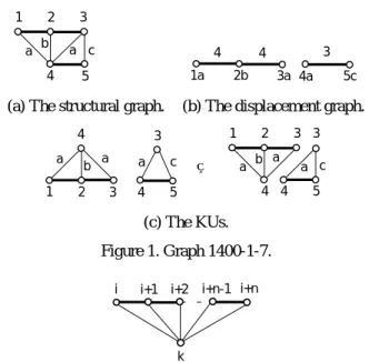
(a) Structural graph: The structural graph shows the topological structure of a GKC by denoting links with vertices, gear pairs with heavy edges, turning pairs with thin edges, and each thin edge is labeled according to its axis orientation in space. Figure 1(a) shows structural graph 1400-1-7 (Freudenstein, 1971), which corresponds to a one-dof, 5-link geared mechanism. (b) Displacement graph: A displacement graph expresses the topological structure of a GKC in an abbreviated form. The
displacement graph of a GKC is obtained from its structural graph by deleting thin edges and transfer vertices, labeling each heavy edge with the corresponding carrier, and labeling each geared vertex according to the axis of the joint connecting the gear and the carrier (Freudenstein, 1971). Figure 1(b) shows the displacement graph associated with Fig. 1(a).
(c) Structurally non-fractionated GKC: A GKC without any cut vertex in its structural graph or its pseudo-isomorphic graph(s) (Tsai and Lin, 1989) is referred to as a structurally non-fractionated GKC.
Since a structurally fractionated GKC can be decomposed into non-structurally fractionated sub-chains by separating the cut vertex, only non-structurally fractionated GKCs shall be discussed in this paper.
3. CONCEPT OF KINEMATIC FRACTIONATION
Freudenstein (1972) introduced the concept of fundamental circuit to represent the minimal kinematic structure in a
structural graph. A fundamental circuit consists of two vertices representing a pair of meshed gears, a vertex representing the associated carrier, and the connecting edges. The kinematic relation in a fundamental circuit can be described as a
fundamental circuit equation. The fundamental circuit formed by vertices i, i+1 and k in Fig. 2 and its associated fundamental circuit equation can be expressed as
1 2 3 4 a b a 5 c 4a 1a 3 2b 4 5c 3a 4
(a) The structural graph. (b) The displacement graph.
1 2 3 4 a b a 3 4 5 a c 1 2 3 4 a b a 3 4 5 a c ⇒ (c) The KUs. Figure 1. Graph 1400-1-7. i i+1 k i+n i+2 i+n-1
Figure 2. A typical KU with connected heavy-edged path.
k , 1 i i , 1 i k , i =e+ θ+ θ (1)
where θi,k is the relative angular displacement between links i and k, and ei+1,i is the gear ratio between gears i+1 and i.
Also, the fundamental circuit formed by vertices i+1, i+2 and k and its associated fundamental circuit equation can be expressed as k , 2 i 1 i , 2 i k , 1 i+ =e+ +θ+ θ (2)
Since gear vertex i+1, and the carrier vertex k are common to both fundamental circuits, Eqs. (1) and (2) have a common variable, θi+1,k. Substituting Eq. (2) into Eq. (1) yields
k , 2 i i , 1 i 1 i , 2 i k , i =e+ + ⋅e+ θ+ θ (3)
Similar substitutions can be repeated along the heavy-edged path. By repeating the substitution of fundamental circuit equations, kinematic relation between two ends of the heavy-edged path can be described with an augmented fundamental circuit equation. For instance, the relation between links i and i+n in Fig. 2 can be expressed as
k , n i i 1, i 2 n i , 1 n i 1 -n i , n i k , i =e+ + ⋅e+ − + − ⋅ e+ θ+ θ L (4)
It can be seen that the augmented fundamental circuit equation lumps the kinematic relations among gears associating with the same carrier. Hence, all fundamental circuits with the same carrier can be gathered to form the basic kinematic structure in a GKC.
From the distribution of carrier(s), basic kinematic structure(s) in a GKC can be identified from its associated displacement graph according to the following procedure:
Step 1. Separate the displacement graph into connected
sub-graphs so that each sub-graph includes all the gear vertices associated with the same carrier.
In Fig. 1(b), each sub-graph associates with one carrier only and thus no further separation is required. Figures 3(a) and (b) show the structural graph and the displacement graph of graph 1400-1-4 (Freudenstein, 1971) respectively. It can be seen that the displacement graph contains two carrier labels. Hence, Figure 3(b) should be separated as shown in Fig. 3(c) in which each sub-graph has only one carrier label.
Step 2. Build gear-carrier pairs in each connected sub-graph by
adding a vertex representing the carrier, connecting the gear and carrier vertices with thin edges and labeling each thin edge with the axis orientation.
Left-hand sides of Fig. 1(c) and Fig. 3(d) show the results obtained from Fig. 1(b) and Fig. 3(c) respectively.
Step 3. Obtain kinematic units (KUs) by connecting the common
vertices in each sub-graph obtained from Step 2 with a thin edge.
In Fig. 1(c), each sub-graph has already a thin edge connecting the common vertices 3 and 4. Hence, each connected sub-graph in Fig. 1(c) represents a KU which can be rearranged as shown in the right-hand side. In the left-hand side of Fig. 3(d), it can be seen that vertices 1 and 5 are common to both connected sub-graphs. One of the sub-graph has already a thin edge connecting vertices 1 and 5 directly while another sub-graph uses a thin-edged path, 1 - 3 - 5, to connect vertices 1 and 5. It is known that the connection among vertices with thin edges
having the same label can be rearranged arbitrarily without any kinematic deviation (Tsai, and Lin, 1989). Hence, a thin edge can be relocated between vertices 1 and 5 since the path 1 - 3 - 5 has a unique axis label. The rearranged result is shown in the right-hand side of Fig. 3(d) in which each connected sub-graph represents a KU.
According to the above procedure, all the KU(s) contained in a GKC can be identified. Each KU represents a basic kinematic structure. In each KU, the kinematic dependency between links is governed by the augmented fundamental circuit equation. Since motion is transmitted along the heavy-edged path, vertices on open ends of the heavy-edged path can be regarded as ends of motion transmission of a KU. As a GKC contains more than one KU, the end of motion transmission of the entire GKC should take the connecting condition between KUs into consideration. The end of motion transmission of the entire GKC is referred to as an end vertex, which can be identified from KUs according to the following definition:
End ver tex: An end vertex of a GKC is a vertex, which is
on an open end of the heavy-edged path of a KU but is not common with another KU.
3 1 2 5 4 a b a c 2b 4c 3 1a 5 5a 3
(a) The structural graph. (b) The displacement graph.
2b 4c 3 1a 5 5a 3 1a
(c) The separated displacement graph.
1 3 4 5 5 2 a a a c b 1 3 1 2 5 a b a c 5 1 4 ⇒ (d) The KUs. Figure 3. Graph 1400-1-4.
As shown in Fig. 1(c), vertices 1, 3, 4 and 5 are on the open ends of the heavy-edged paths in associated KUs. Since vertices 3 and 4 are the common vertices between the two KUs, only vertices 1 and 5 are end vertices.
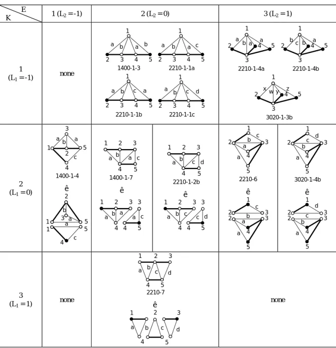
By categorizing according to the number of KUs, K, and the number of end vertices, E, the associated KU(s) and end vertices
of the thirteen one-dof, 5-link structurally non-fractionated GKCs (Freudenstein, 1971) are determined as shown in Table 1 in which each dark vertex represents an end vertex. It can be seen that seven of the thirteen GKCs have only one KU and thus is classified as kinematically non-fractionated. For a kinematically non-fractionated GKC, the associated KU is identical to the GKC itself. The remaining six GKCs has more than one KUs and are classified as kinematically fractionated.
4. TOPOLOGICAL REQUIREMENTS OF A GEARED MECHANISM
The obtained KU(s) exposes the kinematic dependency inside the associated GKC. The revealed kinematic insight provides a substantial assistance to accomplish the conceptual design of geared mechanisms by determining admissible locations of the ground, input and output links. In what follows, we shall confine the discussion to ground-actuated mechanisms. The assignment of the ground, input and output links is assumed to satisfy the following basic requirements:
(1) Input link is adjacent to ground.
(2) The motion of every driven link is properly constrained by the input(s).
(3) No redundant links.
4.1 Mobility requir ement
The input link and its supporting link form an actuator pair (Davies, 1968). From the first requirement, each actuator pair should be assigned on a thin edge incident to the ground. Hence, we have
Axiom 1: The number of thin edges incident to the ground is
equal to or larger than the number of dof of the mechanism, F. The relative angular displacement between the actuator pair is used as a given information to determine the motion of other links. A link is said to be properly constrained if its motion can be determined according to the motion of actuator pair(s). With the concept of kinematic fractionation, the motion of a link is lumped with other links in the same KU. From Eq. (4), it can be seen that once the motion of an actuator pair is assigned in a KU, the motion of other links will be determined sequentially along the heavy-edged path. Thus, we have
Axiom 2: A KU can contain at most one actuator pair.
With the single input, the motion of each link inside the KU is completely constrained.
In addition, a mechanism with properly constrained motion should obey the following axiom:
Axiom 3: The total number of actuator pairs is equal to the
Table 1. KUs and end vertices of one-dof, 5-link GKCs. E K 1 (L2 = -1) 2 (L2 = 0) 3 (L2 = 1) 1 (L1 = -1) none 2 3 4 5 1 a b a b 1400-1-3 2 3 4 5 1 a b a c 2210-1-1a 2210-1-1b 2 3 4 5 1 a b c a 2210-1-1c 2 3 4 5 1 a b c d a b a a 1 2 3 4 5 2210-1-4a 2210-1-4b bc b a 1 2 3 4 5 3020-1-3b x w y z 1 2 3 4 5 2 (L1 = 0) 3 1 2 5 4 a b a c 1400-1-4 ê 3 1 2 5 a b a c 5 1 4 1 2 3 4 a b a 5 c 1400-1-7 ê 1 2 3 4 a b a 3 4 5 a c 1 2 3 4 a b c 5 d 2210-1-2b ê 1 2 3 4 a b c 3 4 5 c d 1 c 5 2 3 4 a a 2210-6 b ê 1 2 3 c b 5 2 3 4 a a 1 d 5 2 3 4 b a 3020-1-4b c ê 1 2 3 d 5 2 3 4 b c a 3 (L1 = 1) none 1 2 a b 4 5 3 c d 2210-7 ê 1 a b 4 5 3 d 2 c none
4.2 Minimum number of output link(s)
Based on a GKC, a geared mechanism is developed such that the number of dof is equal to the number of inputs specified in advance. However, the number of outputs is usually not taken into account. Hence, the topological structure of the GKC only ensures to provide enough mobility but can not guarantee a proper kinematic structure to perform the specified functions.
The ground, input and output links are said to be the ports of a mechanism. Let M be the number of ports in the
mechanism. Since a mechanism can have only one ground link and with the statement in Axiom 3, M can be resolved as
M = 1+ F + P (5)
where P is the number of outputs.
Axiom 4: The number of ports in a mechanism is larger than or
equal to the number of KUs in the associated GKC, i.e.
A link becomes redundant if it has no contribution to transmit motion from the input link to the output link. To avoid redundant links in the mechanism, every end vertex in the GKC needs to be assigned as one of the ports. Hence, the concept of end vertices leads to the following axiom:
Axiom 5: The number of ports in a mechanism is larger than or
equal to the number of end vertices in the associated GKC, i.e.
M ≥ E (7)
By substituting Eq. (5) into Eqs. (6) and (7) respectively and since a mechanism should have at least one output, the number of outputs in a GKC cab be derived as:
P ≥ Max. {1, L1, L2} (8)
where
L1 = K - (1 + F) and (9)
L2 = E - (1 + F) (10)
By examining one-dof, 5-link GKCs in Table 1, it can be determined according to Eq. (9) that
L1 = 1 - (1 + 1) = -1 for kinematically non-fractionated
GKCs (11a)
L1 = 2 - (1 + 1) = 0 for kinematically fractionated GKCs
with 2 KUs (11b)
L1 = 3 - (1 + 1) = 1 for kinematically fractionated GKCs
with 3 KUs (11c)
From Eq. (10), it can be also determined that
L2 = 1 - (1 + 1) = -1 for GKC with 1 end vertex (12a)
L2 = 2 - (1 + 1) = 0 for GKC with 2 end vertices (12b)
L2 = 3 - (1 + 1) = 1 for GKC with 3 end vertices (12c)
By substituting the results of Eqs. (11) and (12) into Eq. (8), it can be concluded that the minimum number of outputs for all the one-dof, 5-link GKCs is one.
5. PROCEDURE FOR TOPOLOGICAL ANALYSIS
Based on the requirements for admissible mechanisms, the procedure to determine the locations of ground, input and output links in a GKC is developed as follows. For the purpose of demonstration, graph 1400-1-7 is selected as an illustrative example with assuming the number of output equal to one, and thus the number of ports, M, is equal to 3.
5.1 Assignment of the gr ound ver tex
From Axioms 1 and 5, the requirements for an admissible location of the ground can be derived as follows:
R1: A vertex can be selected as the ground if the number of incident thin edges is equal to or more than the number of dof of the mechanism.
R2: A vertex is selected as the ground such that the number of end vertices, which is not used as the ground is no more than M - 1.
According to R1 and R2, it can be seen that every vertex in graph 1400-1-7 is eligible to be the ground.
5.2 Assignment of the input link
In a ground-actuated mechanism, the requirements for admissible locations of input link(s) can be derived from Axiom
2 as follows:
R3: A vertex can be selected as input if it is adjacent to the ground vertex with a thin edge.
R4: As more than one input link is required, actuator pairs should be assigned in different KUs.
In addition, another requirement for the input can be derived from R2 as
R5: The input vertices are selected such that the number of end vertices, which are not on the actuator pair(s) is no more than
M - 1 - F.
According to R3, R4 and R5, the input link in graph 1400-1-7 can be selected according to different selections of ground vertices:
(1). Vertex 1 is the ground: Vertices 3 and 4 are adjacent to vertex 1 with a thin edge. It can be found that both of the two vertices satisfy R5. Hence, two admissible combinations of the ground and input links are obtained which can be expressed as [G; I] = [1; 3] and [1; 4].
(2). Vertex 2 is the ground: Vertex 4 is the only one vertex that is connected to vertex 2 with a thin edge. However, if vertex 4 is assigned as the input link, R5 can not be satisfied. Thus, no admissible results can be obtained with vertex 2 being the ground.
(3). Vertex 3 is the ground: Vertices 1, 4 and 5 are adjacent to vertex 3 with a thin edge. However, only vertices 1 and 5 satisfy R5. Thus, the admissible combinations of the ground and input links are obtained as [3; 1] and [3; 5].
(4). Vertex 4 is the ground: Vertices 1, 2 and 3 are adjacent to vertex 4 with a thin edge. However, only vertices 1 satisfies
R5. Thus, the only one admissible combination of the ground
and input links is obtained as [4; 1].
(5). Vertex 5 is the ground: The only one vertex connecting to vertex 5 with a thin edge is vertex 3, which also satisfies R5. Thus, one admissible combination of the ground and input links is obtained as [5; 3].
5.3 Assignment of the output ver tex
According to the requirement described in Eq. (7), admissible locations of output link(s) should content the following requirements:
R6: Each end vertex, which is not on the actuator pair, is assigned as the output link.
R7: In the case that all end vertices are on the actuator pair, any other vertex can be assigned as an output link.
R8: The output link(s) is selected such that each KU contains at least one of the ground, input and output links.
The output link in graph 1400-1-7 can be determined as follows:
Case 1. [G; I] = [1; 3], [1; 4], [3; 1] or [4; 1]: The remaining end vertex is vertex 5. According to R6 and R8, admissible combinations of the ground, input and output links are determined as [G; I; O] = [1; 3; 5], [1; 4; 5], [3; 1; 5], and [4; 1; 5].
Case 2. [G; I] = [3; 5] or [5; 3]: The remaining end vertex is vertex 1. Thus, admissible combinations of the ground, input and output links are determined as [3; 5; 1], and [5; 3; 1].
From Cases 1 and 2, six sets of admissible arrangements of the ports are obtained as listed in Table 2(b). Since these arrangements have more than one carrier, the associated mechanisms have at least one floating carrier. Hence, the resultant configurations are all classified as EGTs.
Based on the above procedure, admissible assignments of the ground, input and output links for one-dof, 5-link kinematically non-fractionated and kinematically fractionated GKCs are obtained as shown in Tables 2(a) and (b) with number of output equal to one. It can be seen that only four ordinary gear trains (OGTs) are obtained in which the unique carrier vertex is used as the ground link. It is also found that no ground-actuated mechanism with one output can be obtained from graph 3020-1-4b.
In Tables 2(a) and (b), seven EGT configurations with both input and output links adjacent to the ground can be found and are denoted with an asterisk. In such configurations, the distinction between the input and output links is unnecessary since the number of inputs and outputs are the same. By disregarding the distinction between input and output links, four distinct EGTs are obtained, which can be expressed as [G; (I/O)] = [2; (1/5)] on graph 2210-1-1b, [2; (4/5)] on graph 2210-1-4a, [5; (3/4)] on graph 1400-1-4 and [3; (1/5)] on graph 1400-1-7.
By comparing the above four EGT configurations with those results obtained by Olson, et al. (1991), it can be found that the results from both approaches come into agreement. However, the coincident-joint-graph approach used an exhaustive method to generate fifty-four possible configurations, in which fifty configurations are found containing redundant link(s) after deriving the kinematic relation between input and output links.
Hence, it is much more time-consuming with the coincident-joint-graph approach (Olson, et al., 1991).
6. CONCLUSION
The concept of kinematic unit is introduced as the basic kinematic structure in a GKC. The identified kinematic units and end vertices depict the kinematic insight in the GKC and provide a clear guidance to prevent inducing redundant links. A systematic approach for the topological analysis of geared mechanisms is developed accordingly. From the approach, admissible assignments for the ground, input and output links can be obtained directly by inspection without deriving kinematic relations between input and output links.
REFERENCES
Davies, T. H., 1968, “An Extension of Manolescu’s Classification of Planar Kinematic Chains and Mechanisms of mobility M ≥ 1, Using Graph Theory,” Journal of Mechanisms, Vol. 3, pp. 87-199.
Erdman, A. G. and Sandor, G. N.,1991, Mechanism Design: Analysis and Synthesis, Vol. 1, Prentice Hall, Inc., Eaglewood Cliffs, NJ.
Freudenstein, F., 1971, “An Application of Boolean Algebra to The Motion of Epicyclic Drives,” ASME Journal of Engineering for Industry, Vol. 93, Series B, pp. 176-182.
Freudenstein, F., 1972, “Kinematics and Statics of a Coupled Epicyclic Spur-Gear Train,” Mechanism and Machine Theory, Vol. 7, pp. 263-275.
Hsu, C. H. and Lin, Y. L., 1994, "Automatic Analysis of the Redundant Gears in Planetary Gear Trains," International Journal of Vehicle Design, Vol. 15, No. 5, pp. 402-415 1993.
Liu, C. P. and Chen, D. Z., 1999, “On the Embedded Kinematic Fractionation of Epicyclic Gear Trains,” submitted to ASME Journal of Mechanical Design," Proceedings of the 1999 ASME Design Engineering Technical Conference, Paper No. DETC99/DAC-8660.
Olson, D. G., Erdman, A. G. and Riley, D. R., 1991, “Topological Analysis of Single-Degree-of-Freedom Planetary Gear Trains,” ASME Journal of Mechanical Design, Vol. 113, pp. 10-16.
Tsai, L. W., 1987, “An Application of the Linkage Characteristic Polynomial to The Topological Synthesis of Epicyclic Gear Trains,” ASME Journal of Mechanisms, Transmissions, and Automation in Design, Vol. 109, No. 3, pp. 329-336.
Tsai, L. W. and Lin, C. C., 1989, “The Creation of Non-fractionated Two-Degree-of-Freedom Epicyclic Gear Trains,”
ASME Journal of Mechanisms, Transmissions, and Automation in Design, Vol. 111, pp. 524-529.