Design and Implementation of an OA&M System
for WLL Network
Jiun-Yao Huang, Hsien-Ming Tsai, Yi-Bing Lin, and Chien-Chao Tseng
Abstract: This paper describes the design and implementation of
an OA&M system for DECT-based WLL network. This system follows the client-server architecture that enables remote manage-ment through the Internet. Object-oriented design is used to yield quality software, where the entire WLL network is treated as a hi-erarchical collection of objects. The “plug-in” mechanism provides the capabilities of replacing and extending OA&M functionalities in run-time. Design patterns are applied to improve the reusabil-ity of software components. Two types of user interfaces are im-plemented in different platforms to provide access to the OA&M system. Although our design is tailored for the WLL network, it is also appropriate to serve as the OA&M system for other small-scale telecommunication systems.
Index Terms: Wireless local loop, OA&M, DECT.
I. INTRODUCTION
Wireless local loop (WLL) provides two-way calling services to the stationary or “fixed” users, which is intended to replace its wireline counterpart. In the recent years, WLL is considered as an alternative to wireline access for the telephony services. Compared with the wireline local loop, the WLL offers advan-tages such as ease of installation & deployment, and concentra-tion of resources [1], [2].
On the other hand, since WLL involves radio resource alloca-tion, management of WLL has higher complexity than its wire-line counterpart. Thus, OA&M (operations, administration, and maintenance) for WLL is more critical than that for wireline local loop. Through OA&M, the WLL network is operated, ad-ministered and maintained by a network operator. For a large wireless telecommunication network, OA&M is typically im-plemented following Telecommunication Management Network (TMN) specification [3]–[8]. Such an approach is too heavy for small-scale systems. This paper demonstrates the design and implementation of OA&M for a small-scale WLL system. Our design is also appropriate for other small-scale telecommunica-tion systems.
Fig. 1 presents the WLL architecture developed by Eumitcom Technology Inc. In this architecture, the base station controller (BSC) is responsible for interfacing the WLL network to local exchange (LE). The connections between a BSC and the LE are tip/ring lines (or T1) with a concentrator. The radio base sta-Manuscript received July 20, 1999; approved for publication by Veli Sahin, Division III Editor, May 3, 2000.
The Authors are with Dept. Comp. Sci. & Info. Eng., National Chiao Tung University, Hsinchu, Taiwan, R.O.C., e-mail: jyhuang@csie.nctu.edu.tw, jt-sai@csie.nctu.edu.tw, liny@csie.nctu.edu.tw, cctseng@csie.nctu.edu.tw.
1229-2370/00/$10.00 c 2000 KICS
tion (RBS) acts as the wireless access point for the radio net-work termination (RNT). The air interface between the RBS and the RNT follows the ETSI Digital Enhanced Cordless Telecom-munications (DECT) standard [9]. The RNT is responsible for converting and delivering the voice and control signaling be-tween the CPE (through subscriber telephone lines) and the RBS (through the DECT air interface). The CPE (customer premise equipment) is typically a telephone set. The concentrator per-forms concentrating and mapping functions between 576 lines in the LE and 64 lines in a BSC. The dashed area illustrates the OA&M system (WLL-OAM) for the WLL network. WLL-OAM monitors the WLL network remotely through Internet.
We describe a design and implementation of WLL-OAM for
small-scale WLL network. This paper is organized as
fol-lows. Section II discusses the OA&M management functions for WLL. Section III presents the WLL-OAM architecture. Sec-tion IV describes the communicaSec-tion protocols for WLL-OAM. Section V discusses the WLL-OAM software design. For the reader’s benefit, Table 1 provides an acronym list used in this paper.
II. WLL OA&M MANAGEMENT FUNCTIONS The WLL OA&M system provides the OA&M services to control and monitor the equipment in the WLL system. The network elements managed by WLL-OAM are BSC, RBS, RNT, and CPE. Five types of OA&M management functions are pro-vided in WLL-OAM.
1) Type 1: The network configuration functions report the configuration information of the WLL.
2) Type 2: The network element status functions monitor the status of the WLL network elements.
3) Type 3: The failure detection functions detect the er-rors/failures occurring in the WLL network elements. 4) Type 4: The testing functions test the functionalities and
qualities of the network elements.
5) Type 5: The call statistics functions provide call perfor-mance of the WLL network.
For BSC, the Type 1 function is system configuration that pro-vides the topology information for the WLL network, including equipped RBSs and registered RNTs connected in the network. The Type 2 function is BSC information that includes the BSC ID, date/time, bootstrap indication, etc. The date and time of a BSC are used to synchronize the time-related information be-tween the OA&M system and the BSC. Bootstrap indication records the time when the BSC is re-booted. The Type 3 func-tion is board failure detecfunc-tion that reports the circuit board
fail-BSC: Base Station Controller RBS: Radio Base Station
RNT-1: Radio Network Termination with single port RNT-4: Radio Network Termination with 4 ports CPE: Customer Premise Equipment
BSC Public Switched Telephone Network T/R #0 T/R #575 Internet OA&M server Modem OA&M Client Modem RBS RBS RBS DECT (air interface) CPE RNT-1 CPE CPE CPE CPE CPE RNT-4 CPE RNT-1 RNT-1 OA&M Center other WLL networks Concentrator Local Exchange WLL-OAM RS232 other servers
Fig. 1. The wireless local loop.
Table 1. Acronyms.
BSC base station controller
CI command interpreter
CPE customer premise equipment
DECT Digital Enhanced Cordless Telecommunications
DLL dynamic-link library
DOC distributed object computing
DTP data transfer process
GUI graphical user interface
MEI message-exchange interface
OA&M operations, administration, and maintenance
RBS radio base station
RNT radio network termination
STL standard template library
TCP/IP Transmission Control Protocol/Internet Protocol
UCI user-command interface
UML Unified Modeling Language
WLL wireless local loop
ures in the BSC. When the OA&M system detects a failure, it alerts the operator. The Type 4 function is loopback test used to verify the availability of transmission between the OA&M sys-tem and the BSC.
For RBS, no Type 1 function is defined. The Type 2 function is RBS information including the RBS ID, channel assignment, etc. The Type 3 functions include power failure detection and RBS failure detection. The Type 4 function is RBS loopback test that verifies the availability of the transmission between the RBS
and the BSC.
For RNT, the Type 1 functions include registration and dereg-istration that allow an RNT to attach and detach the WLL sys-tem. The registration function authenticates an RNT, and the deregistration function cancels authority of an RNT. The Type 2 functions include RNT information and CPE presence detec-tion. The RNT information includes the RNT ID, attached CPE ID, registration status, DECT identities, password, etc. The CPE presence detection helps the operator to confirm whether the un-reachable calling service is caused by the customer. The Type 3 functions include power failure detection and low battery volt-age detection that allow the OA&M system to detect power fail-ure and abnormality of backup battery. The Type 4 functions include ring/ring trip test, tone generation test, and RNT loop-back test. The ring/ring trip test instructs the RNT to ring the CPE. This test verifies the availability of transmission between the BSC and the CPE. The tone generation test instructs the RNT to generate a tone to the CPE. The tone patterns include dial tone, busy tone, ring tone, etc. This test helps the operator to verify the tone generation functions on the RNT. The loopback test verifies the availability of transmission between the RNT and the BSC. The Type 5 functions perform statistics of call at-tempts, RSSI (received signal strength indication) measurement, and FER (frame error rate) detection. The call statistics includes the number of successful call attempts, the number of dropped call attempts, and the number of blocked call attempts. The op-erator uses this information to reallocate wired and wireless re-sources in network planning. The RSSI indicates radio signal strength received by the RNT during a call conversation. The
OA&M Software
WLL Network
OA&M Part
OA&M Support Part User Presentation Part
Message-Exchange Interface
Fig. 2. OA&M software architecture.
FER value is measured to evaluate the radio link quality during a call conversation.
III. THEWLL-OAM ARCHITECTURE
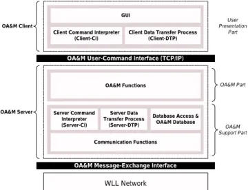
Fig. 2 illustrates a common OA&M software architecture con-sisting of three parts: user presentation part, OA&M part, and OA&M support part [10].
The user presentation part provides a man-machine interface to the OA&M system. The OA&M part provides the primary OA&M management functions to monitor and control the WLL network. The OA&M support part provides database access functions, communication functions, and other miscellaneous functions. The OA&M system exchanges messages with the WLL network through message-exchange interface (MEI).
The WLL-OAM design follows the client-server approach where the software is separated into two parts: OA&M client and OA&M server. The OA&M client is responsible for user presentation, which provides a graphical user interface (GUI) for OA&M users. The OA&M server passively waits for re-quests from OA&M clients and then provides the OA&M ser-vices to the clients. The OA&M client and the OA&M server exchange messages through a TCP/IP application-level proto-col called user-command interface (UCI). Fig. 3 illustrates the details of the client-server-based WLL-OAM architecture. In this architecture, the OA&M client consists of three modules: graphical user interface interface (GUI), client command in-terpreter CI), and client data transfer process (client-DTP). The GUI provides a friendly interface to the operator. The client-CI is responsible for transferring UCI commands, and the client-DTP is responsible for transferring OA&M data.
The OA&M server consists of six modules: OA&M functions, server command interpreter (server-CI), server data trans-fer process (server-DTP), database access functions, OA&M database, and communication functions. The OA&M functions control, monitor, test, and debug the WLL network. The server-CI “listens” on a certain TCP port for a connection requested from a client-CI and then establishes a control session. It re-ceives commands from client-CI through UCI, sends the corre-sponding replies for the commands, and then governs the
server-WLL Network
OA&M Message-Exchange Interface OA&M User-Command Interface (TCP/IP)
Client Command Interpreter (Client-CI)
GUI
Server Command Interpreter (Server-CI)
Database Access & OA&M Database Communication Functions
OA&M Functions OA&M Client
OA&M Server
Client Data Transfer Process (Client-DTP) Server Data Transfer Process (Server-DTP) User Presentation Part OA&M Support Part OA&M Part
Fig. 3. Modules of the client-server-based WLL-OAM architecture.
MSB
LSB
7 6 5 4 3 2 1 0
command
message type message ID
data length (N) data (N bytes)
Fig. 4. MEI message format.
DTP for data transfer. The server-DTP establishes a connection on demand from server-CI and then transfers data to and from the client-DTP through this connection. The database access functions retrieve and store data in the OA&M database. The OA&M database contains the information for system configu-ration, RNT registconfigu-ration, OA&M data, etc. The communica-tion funccommunica-tions provide the capabilities of communicacommunica-tion with the WLL network.
IV. COMMUNICATION PROTOCOLS
Two communication protocols are developed in WLL-OAM: The message-exchange interface (MEI) and user-command in-terface (UCI). The MEI inin-terfaces the OA&M server with WLL networks. The UCI supports communication between OA&M clients and the OA&M server.
A. OA&M Message-Exchange Interface
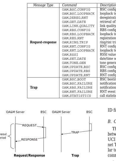
OA&M MEI is a reliable serial communication protocol, which exchanges OA&M messages between WLL-OAM and a BSC. The MEI message format is shown in Fig. 4. The 8-bit command is used to specify OA&M service. Some of the MEI commands are listed in Table 2. The message type indicates the type of a message, which can be request, response, or trap (to be elaborated later). The message ID is used to distinguish the out-standing messages so that more than one message of the same MEI command can be issued simultaneously. The message ID is used by the OA&M server to correlate incoming responses with the corresponding outstanding requests. The data length
Table 2. An incomplete list of MEI commands. Message Type Command Description
Request-response
OAM BSC CONFIG BSC configuration (ID, topology information, etc.) OAM BSC LOOPBACK loopback test for BSC
OAM DEREG RNT deregistration of RNT OAM GET DATE retrieval of date/time for BSC OAM LINK QUALITY link quality detection (frame error rate) OAM RBS CONFIG RBS configuration (ID, channel assignment, etc.) OAM RBS LOOPBACK loopback test for RBS
OAM REG RNT registration of RNT OAM RING TRIP ring/rint trip test
OAM RNT CONFIG RNT configuration (ID, password, IPUI, IPEI, etc.) OAM RNT LOOPBACK loopback test for RNT
OAM RSSI RSSI value of RNT OAM SET DATE date/time setup for BSC OAM TONE GEN tone generation test OAM UPDATE BSC BSC configuration update OAM UPDATE RBS RBS configuration update OAM UPDATE RNT RNT configuration update
Trap
OAM BSC BOOT BSC booting indication
OAM BSC FAILURE notification of BSC failure (board failure) OAM RBS FAILURE notification (power failure, RBS failure, etc.)
OAM RNT FAILURE RNT event notification (power failure, RNT failure, etc.) OAM STATISTICS call statistics (dropping, blocking calls, etc.)
OA&M Server BSC REQUEST RESPONSE OA&M Server BSC timeout period Trap TRAP Request/Response
Fig. 5. MEI transmission paradigm.
indicates the length of data in bytes. Since the bit length of the data length field is 8 bits, the data length is limited to 255 bytes and the total message length is limited to 258 bytes (255 bytes plus 3 bytes for message header).
As shown in Fig. 5, two kinds of transactions are defined in the MEI transmission paradigm: request-response and trap. The request-response transaction is used by the OA&M server to re-trieve the WLL information. The WLL (specifically, the BSC) utilizes traps to inform the WLL-OAM of significant events.
In a request-response transaction, the OA&M server sends the request messages to the BSC to invoke some OA&M rou-tines, and the response message acknowledges the correspond-ing request message. Every request-response transaction is as-sociated with a timeout timer controlled by the OA&M server. If the timer expires, the transaction is regarded as a failure. The message type of a request message is OAMMT REQUEST, and the message type of a response message is OAMMT RESPONSE. Both request and response messages in a request-response trans-action have the same message ID.
Trap messages are issued from a BSC without any acknowl-edgement, which allow the OA&M system to receive asyn-chronous notification of significant events in the WLL network. A trap message is of the type OAMMT TRAP. Different trap oper-ations are distinguished by their command names. The message
ID field is ignored in a trap message. B. OA&M User-Command Interface
The user-command interface (UCI) supports communication between the OA&M server and multiple OA&M clients. The UCI is a TCP/IP application-level protocol compliant to Inter-net TelInter-net protocol [11]. UCI transmission mechanism is simi-lar to Internet File Transfer Protocol [12], which uses two TCP connections to transfer OA&M information.
1. The control connection is used for UCI command trans-mission. This connection is established in the normal client-server fashion. That is, the OA&M server performs a passive open1 on the port for OA&M and waits for a
connection from an OA&M client. The client performs an active open to the OA&M port to establish the control connection. The control connection stays up during the client-server communication session. The command in-terpreters (CIs) are responsible for managing the control connection.
2. The data connection is created when the OA&M data are transferred between a client and the server. The data trans-fer processes (DTPs) are responsible for managing the data connection.
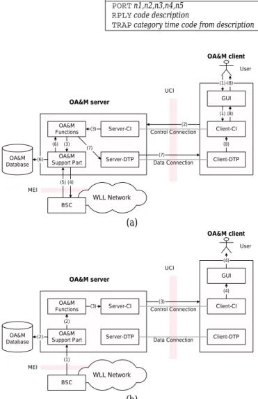
Table 3 shows the nine commands defined for OA&M client. Table 4 shows the three UCI commands defined for OA&M server.
C. Examples of OA&M Information Exchange
This section gives two examples for OA&M information ex-change. The first example utilizes the request-response transac-tion paradigm, which is illustrated in Fig. 6 (a) with the follow-ing steps.
1
In TCP/IP terminology, the side that sends the first TCP packet with SYN flag set is said to perform an active open. The other side, which receives this TCP SYN package and sends the next TCP SYN package, performs a passive open.
Table 3. UCI commands for client. Command with optional parameters Description
ABOR aborting previous UCI command and any data transfer ACTNaction parameters performing an action
GETDitem parameters retrieving OA&M data
HELP help menu for human reading only
NOOP no operation (intended to test the control connection)
PASSpassword password
QUIT logout from the server
SETDitem parameters storing OA&M data
USERusername username
Table 4. UCI commands for server. Command with parameters Description
PORTn1,n2,n3,n4,n5 indicating IP address (n1.n2.n3.n4) and port (n5) RPLYcode description acknowledgement of the client command TRAPcategory time code from description notifying significant events
WLL Network Server-CI OA&M server Server-DTP Client-CI OA&M client Client-DTP GUI OA&M Database BSC Data Connection Control Connection (2) OA&M Support Part UCI OA&M Functions User MEI (1) (1) (3) (3) (4) (5) (7) (6) (7) (6) (8) (8) (8) (a) WLL Network Server-CI OA&M server Server-DTP Client-CI OA&M client Client-DTP GUI OA&M Database BSC Data Connection Control Connection (3) OA&M Support Part UCI OA&M Functions User MEI (3) (1) (2) (2) (4) (4) (b)
Fig. 6. OA&M information exchange: (a) OA&M data access, (b) signifi-cant event notification.
Step 1 – The user issues a UCI command through the GUI of the OA&M client.
Step 2 – This command is generated by client-CI, and is sent to the OA&M server via the UCI control connection.
Step 3 – The server-CI invokes the OA&M functions to exe-cute the command.
Steps 4–6 – The OA&M functions utilize the OA&M support part to retrieve the OA&M data from the BSC via MEI and then stores the data in the OA&M database.
base library (C library, STL, etc) general library application library application OS (Windows, Java VM) hardware (IBM PC) layers implemented in WLL-OAM existing platforms
Fig. 7. Layers in WLL-OAM design.
Steps 7 and 8 – The OA&M server uses server-DTP to trans-fer the data to the client via the UCI data connection. Finally, the client-DTP receives the data and the GUI presents the data to the user.
The second OA&M information exchange example shows how a BSC issues a trap to the WLL-OAM. The example is illustrated in Fig. 6 (b) with the following steps.
Step 1 – The BSC raises a trap to the OA&M server through MEI.
Step 2 – The OA&M support part receives the trap, stores it to the OA&M database.
Step 3 – The OA&M server invokes OA&M functions to pro-cess this trap and instruct server-CI to send the results to the OA&M client via the UCI control connection.
Step 4 – The client logs the trap and displays it on the trap page to alert the user.
The details for GUI, client-DTP, server-DTP, OA&M func-tions, and OA&M support part will be discussed in the next sec-tion.
V. OA&M SOFTWARE DESIGN
The WLL-OAM design follows object-oriented approach where the entire WLL network is treated as a hierarchical col-lection of objects managed by the OA&M system. We also ap-ply the design patterns [13] concept in WLL-OAM to provide reusable designs and architecture (to be elaborated later).
The WLL-OAM design is structured in layers as shown in Fig. 7. The hardware platform is IBM PC, and the operating
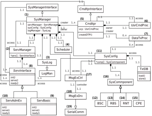
servManager : ServManager sysConfig : SysConfig logManager : SysLog SysManager createDTP() ucp : UsrCmdProc CmdItpr UsrCmdProc CmdItprInterface SysManagerInterface 1..1 1..1 owner 1..1 1..1 *serv[] : ServInterface ServManager init() serve() ready() ServInterface 1..1 1..n init() serve() ready() ServAdmEx init() serve() ready() ServBasic 1..1 1..n access 1..1 1..n access LogMan Scheduler 1..1 1..n creater 1..1 1..1 1..1 1..1
SysLog *comp[] : SysCommponent
SysConfig 1..1 1..1 owner DataTxProc 1..1 0..n creater SerialComm MsgExDrv MsgExCtrl 1..1 1..1 controller 1..1 1..1 1..1 1..1 access SysCommponent 1..1 1..1 access 1..1 1..1 access BSC RBS RNT CPE 1..1 1..n load() store() TxtDB 0..n 1..1 access 1..1 1..n access 1..1 1..1 access (1) (2) (3) (4) (6) (7) (8) (9) (10) (17) (11) (16) (12) (13) (14) (15) (19) (18) (5)
Fig. 8. Class diagram of OAMserv.
system is Microsoft Windows or Java VM. The standard C li-brary and C++ standard template lili-brary (STL) are used as the base library for WLL-OAM implementation. The WLL-OAM general library includes general functions for database access, debugging, logging facility, statistics, etc. The application li-brary provides OA&M specific functions such as serial commu-nication classes, UCI-model classes, “service plug-in” mecha-nism, system configuration class, scheduler, etc.
WLL-OAM consists of an OAMserv (OA&M server) and
several OAMclis (OA&M clients). The client-server model
helps WLL-OAM to decentralize the user interface from the OA&M functions. OAMserv and OAMcli may be distributed into two independent programs running on different hosts. The client is responsible for the user interface, and the server is re-sponsible for the OA&M functions. Both the client and the server can extend their functionalities autonomously. A client can have different styles for user interface, ranging from a plain command-line interface to a fancy graphical interface, which would not affect the performance or correctness of the server.
In the current WLL-OAM version, we have implemented two styles of OAMclis: OAMst and OAMjava. OAMst is a stand-alone application implemented in C++ and OAMjava is a web-based application implemented in Java. OAMjava is a portable Java applet program, which provides the web-based OA&M management for the WLL network. The user can use a gen-eral web browser (e.g., Netscape or Internet Explorer) to operate OAMjava.
A. OA&M Server Design
Fig. 8 illustrates the UML (Unified Modeling Language) class diagram [14] of OAMserv, which consists of a collection of classes listed in Table 5. These classes are grouped into six
cat-egories: system management, OA&M service plug-in, OA&M service management, MEI communication, UCI communica-tion, and WLL information management. In the OA&M ar-chitecture in Fig. 3, the OA&M functions are implemented by the OA&M service management classes. To provide convenient OA&M service management, the OA&M service plug-in classes are designed to support service “plug-in” mechanism (to be dis-cussed in Section V-A.2). The message-exchange functions are implemented by the MEI communication classes, the server-CI and the server-DTP are implemented by the UCI communica-tion classes. The database access and OA&M database are im-plemented by the WLL information management classes. The system management class organizes all classes in OAMserv.
The concept of design patterns are used to implement the OA&M server classes. Design patterns are descriptions of com-municating objects and classes customized to provide reusable designs and architectures. The design patterns utilized in the server design include: Singleton, Facade, State, Observer, Itera-tor, etc.
A.1 System Management Class
The SysManager (system manager) object ((1) in Fig. 8) is created immediately after OAMserv is executed. This object is responsible for coordinating the following OAMserv objects. A
ServManager(service manager) object manages the available
OA&M services ((2), Fig. 8). A SysConfig (system configu-ration) object organizes the OA&M data ((11), Fig. 8). A
Ms-gExCtrl(MEI controller) object exchanges OA&M messages
with a BSC through the MEI protocol ((17), Fig. 8). A SysLog (system log) object logs the significant information of WLL sys-tem ((3), Fig. 8). A Scheduler object periodically invokes management routines ((4), Fig. 8). In addition, some CmdItpr
Table 5. The server classes.
Category Class Description
System management SysManager System manager
OA&M service plug-in
ServInterface Service interface (abstract class) ServBasic Basic services for WLL OA&M ServAdmEx Extended administration services OA&M service management ServManager Service manager
MEI communication MsgExCtrl MEI controller
MsgExDrv MEI driver
UCI communication
CmdItpr Command interpreter
UsrCmdProc User command process DataTxProc Data transfer process
WLL information management
SysConfig System configuration
SysComponent System component (abstract class) BSC, RBS, RNT, and CPE BSC, RBS, RNT, and CPE SysLogand Scheduler System log and OA&M scheduler
TxtDB Text-based database management
(command interpreter) objects are dynamically created to estab-lish the UCI control connections for new clients ((5), Fig. 8).
Since SysManager is the kernel of OAMserv, the Singleton pattern is utilized in the SysManager class to ensure that this class only has one instance with a global point of access. A.2 OA&M Service Plug-in Classes
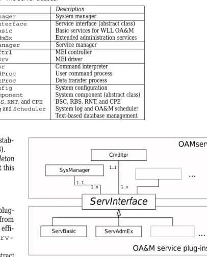
OAMserv treats a set of OA&M functions as a “service plug-in.” The service plug-in can be attached to or detached from OAMserv dynamically. A new OAMserv function can be effi-ciently extended by attaching a service plug-in through
Serv-Interface(service interface).
The ServInterface class ((8) in Fig. 8) is an abstract class2that provides a unified interface for OA&M service
plug-ins. In our current design, there are two subclasses of Serv-Interface: the ServBasic ((9), Fig. 8) class that provides the OA&M management functions (e.g., RSSI measurement) and the ServAdmEx class ((10), Fig. 8) that provides extended administration functions (e.g., server shutdown) for OAMserv. Fig. 9 illustrates the relationship between OAMserv and the service ins. Facade pattern is utilized by service plug-ins to provide a unified interface (i.e., ServInterface) to OAMserv [13]. Facade pattern promotes loose coupling be-tween OAMserv and its plug-ins, so that the modification on a service plug-in does not affect the OAMserv.
In the OAMserv design, a service plug-in is a dynamic-link library (DLL) in Microsoft Windows. A DLL is an executable file that acts as a shared library of functions. Dynamic linking allows a process to call a function that is not part of its exe-cutable code. With DLL, the classes in the OAMserv design are build-time modular, and the service plug-ins are run-time mod-ular. The service plug-in design reduces the cost for upgrading software. Detaching the old plug-in and attaching the new one do not require re-compiling the whole software and can be done in run-time.
A.3 OA&M Service Management Classes
The ServManager object ((2), Fig. 8) is a Singleton ob-ject created by SysManager when OAMserv is executed.
2
An abstract class is a class whose primary purpose is to define an interface. It defers some or all its implementation to subclasses, and it cannot be instantiated.
OA&M service plug-ins OAMserv
ServInterface
ServAdmEx ServBasic SysManager 1..1 1..n CmdItpr 1..1 1..n...
...
Fig. 9. The Facade pattern concept in the OAMserv design.
ServManagermanages the OA&M services implemented by
the classes derived from ServInterface ((8), Fig. 8). The
SysManagerobject invokes the OA&M functions by querying
the services from the ServManager object. A.4 MEI Communication Classes
The MEI is implemented by the MsgExCtrl class ((17), Fig. 8) for communication with a BSC. The MsgExCtrl object aggregates an MsgExDrv object ((18), Fig. 8) to enable serial communication via an RS232 port with a BSC. The MsgExDrv (MEI driver) class inherits the the RS232 communication capa-bility from a general-purpose class called SerialComm ((19), Fig. 8).
When the MsgExCtrl receives a trap message, it ripples through the ServManager, SysConfig, and CmdItpr ob-jects to handle this trap. Observer pattern is applied to these classes, which defines a one-to-many dependency between ob-jects so that when one object changes state, all its dependencies are notified and updated automatically [13].
A.5 UCI Communication Classes
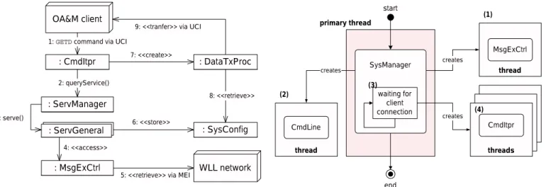
When an OA&M client connects to the server, a control con-nection is established and a CmdItpr (command interpreter) object at the server is created to operate on this connection. The CmdItpr object ((5), Fig. 8) interprets the UCI commands
: CmdItpr : ServManager 2: queryService() : DataTxProc 7: <<create>> : ServGeneral 3: serve() : SysConfig : MsgExCtrl 4: <<access>> WLL network
5: <<retrieve>> via MEI 6: <<store>>
8: <<retrieve>>
OA&M client
1: GETD command via UCI
9: <<tranfer>> via UCI
Fig. 10. Interaction diagram for the GETD command.
from the client, and its UsrCmdProc object ((6), Fig. 8) ex-ecutes these commands. When a data transfer is required, a DataTxProc(data transfer process) object ((7), Fig. 8) is dy-namically created to handle the corresponding data connection. State pattern is applied on the UCI implementation. This pat-tern allows an object to alter its behavior when its inpat-ternal state changes [13]. As an example, Fig. 10 shows the interaction
dia-gram3of a GETD command.
Step 1 – When an OA&M client issues a GETD command via UCI, the CmdItpr object in the OA&M server receives this command.
Step 2 – The CmdItpr object invokes the
querySer-vice()method to search the service plug-in (e.g., a
ServBa-sicobject) that handles this command.
Step 3 – The ServManager object calls the serve() method of this plug-in to perform service function.
Steps 4 and 5 – The ServGenernal object instructs
Ms-gExCtrlobject to retrieve the OA&M data via MEI.
Steps 6–9 – The OA&M data are stored in the SysConfig object. Finally, the CmdItpr object creates a DataTxProc for transferring data.
A.6 WLL Information Management Classes
As we mentioned in Section II, four WLL network elements are managed by WLL-OAM. The OA&M data for these net-work elements are implemented by the BSC class ((12), Fig. 8), the RBS class ((13), Fig. 8), the RNT class ((14), Fig. 8), and the CPE class ((15), Fig. 8). These classes inherit from the ab-stract class SysComponent ((16), Fig. 8). The OA&M data maintained in a SysComponent object are related to the man-agement functions described in Section II. For example, a RNT object contains RNT ID, password, call statistics, registration status, etc.
The SysConfig class ((11), Fig. 8) is intended to manage these objects, which supports object persistence for its managed objects. This persistence mechanism automatically stores an ob-ject to a persistent storage device (hard disk, for example) to
re-3
A UML interaction diagram illustrates a set of objects and their relationships, including the messages that may be dispatched among them [14].
serving threads serving threads start threads end CmdItpr thread creates thread creates CmdLine MsgExCtrl primary thread (1) (2) (3) (4) SysManager waiting for client connection creates (3)
Fig. 11. Multithreaded programming in OAMserv.
tain the state of this object that may be retrieved later. When the
SysConfigobject is created by SysManager, it performs
the persistence function to load the system configuration from database into memory.
The BSC, RBS, RNT, and CPE classes inherit the persistence capability from their base class SysComponent. The persis-tent data are stored in the OA&M database, which is a file-based database managed by the TxtDB class. The data in the TxtDB database are stored in the plain-text (ASCII) format that allows porting to various software/hardware platforms.
The OA&M data in a SysConfig object must be consis-tent with that in the WLL network. A cache mechanism is in-cluded in the SysConfig design to minimize the communica-tion overhead between the OA&M server and a BSC.
A.7 Multithreaded Programming
OAMserv is implemented on the Win32 environment (Mi-crosoft Windows 95/98/NT) using preemptive multitasked and multithreaded programming. The use of multiple threads pro-vides modular design for WLL-OAM. As shown in Fig. 11, when the main program of OAMserv is executed, the primary thread (for SysManager) will create a thread to control the MEI (by MsgExCtrlclass; see Fig. 11 (1)) and another thread to process command-line inputs (using CmdLine class; see Fig. 11 (2)). The primary thread then binds a TCP port and waits for client connection ((3), Fig. 11). For each client, it creates a thread to maintain a UCI session ((4), Fig. 11).
B. OA&M Client Design
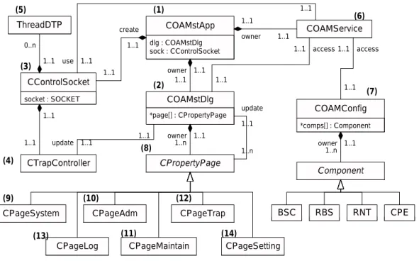
Fig. 12 illustrates the UML class diagram of OAMcli, which consists of a collection of classes listed in Table 6. These classes are grouped into three categories: GUI classes, UCI communi-cation classes, and UCI command classes. In the OA&M archi-tecture in Fig. 3, the GUI is implemented by the GUI classes. The client-CI and the client-DTP are implemented by the UCI communication classes. The UCI commands and the WLL in-formation management are implemented by the UCI command classes.
dlg : COAMstDlg sock : CControlSocket COAMstApp *page[] : CPropertyPage COAMstDlg 1..1 1..1 owner socket : SOCKET CControlSocket 1..1 1..1 create CTrapController 1..1 1..1 COAMService CPageSystem CPageAdm CPageMaintain CPageTrap CPropertyPage CPageSetting 1..1 1..1 owner 1..1 1..1 access 1..n 1..1 owner *comps[] : Component COAMConfig 1..1 1..n update Component BSC RBS RNT CPE 1..n 1..1 owner 1..1 1..1 access 1..1 1..1 update 1..1 1..1 use CPageLog ThreadDTP 0..n 1..1 (1) (2) (5) (3) (4) (7) (6) (8) (9) (10) (13) (11) (12) (14)
Fig. 12. Class diagram of OAMcli. Table 6. The client classes.
Category Class Description
GUI classes
COAMstApp OAMst application
COAMstDlg OAMst dialog box
CPageSystem, CPageAdm, CPageMaintain, CPageLog, CPageTrap, and CPageSetting
System page, administration page, maintenance page, log page, trap page, and setting page.
UCI communication classes
CControlSocket UCI control socket
ThreadDTP Client-DTP thread
CTrapController Trap controller
UCI command classes COAMService OA&M services
COAMConfig OA&M configuration
B.1 GUI Classes
COAMstApp((1), Fig. 12) is the main class that aggregates
other classes in OAMcli, including COAMstDlg (main dialog) class for the user interface ((2), Fig. 12), CControlSocket (UCI control socket) class for UCI ((3), Fig. 12), CTrap-Controller(trap controller) class for the OA&M traps ((4), Fig. 12), COAMService (OA&M services) class for OA&M services ((6), Fig. 12), etc.
The COAMstDlg class implements the main dialog box that contains several pages for various OA&M categories. The pages are implemented by the GUI page classes derived from
CProp-ertyPage ((8), Fig. 12). These page classes provide
con-tents for OA&M user interface, including CPageSystem ((9), Fig. 12) for system view, CPageAdm ((10), Fig. 12) for admin-istration, CPageMaintain ((11), Fig. 12) for maintenance,
CPageTrap ((12), Fig. 12) for OA&M traps, CPageLog
((13), Fig. 12) for system logs, and CPageSetting ((14), Fig. 12) for miscellaneous settings.
A GUI derived from OAMcli is protected by a login/password
mechanism. The system-view page provides a hierarchical
OA&M information of the WLL network, including BSC, RBS, RNT, and CPE. Each level of the OA&M information is
associ-ated with a floating menu. This menu provides the access to the corresponding scope of OA&M. The administration page pro-vides the OA&M data retrieval. The maintenance page propro-vides the capability for testing. The trap page is used to monitor the WLL network. The logging page is used to record some sig-nificant information. The setting page is used to set IP address, port, user name, GUI parameters, etc.
B.2 UCI Communication and Command Classes
The client-CI is implemented in the CControlSocket class ((3), Fig. 12), which is responsible for controlling UCI. The client-DTP is implemented in the ThreadDTP objects ((5), Fig. 12), which is dynamically created for data transfer.
The CTrapController class deals with traps sent from the OA&M server. It notifies the COAMstDlg object of the occurrences of traps, and the COAMstDlg object updates the user interface to alert the user.
The COAMService object ((6), Fig. 12) is used to instructs
CControlSocketto perform the UCI commands via UCI.
The COAMConfig class ((7), Fig. 12) maintains the WLL in-formation (stored in BSC, RBS, RNT, and CPE objects), which is consistent with the OA&M data maintained on the server side.
VI. CONCLUSION
This paper described the design and development of an OA&M system, WLL-OAM, for a DECT-based WLL network. Our design is also appropriate for other small-scale telecommu-nication systems. Based on the object-oriented approach, the WLL-OAM has the following features.
The client-server architecture provides flexibility and scalability, which supports remote management through Internet or other data networks. Multiple OA&M clients can control and monitor an OA&M server simultaneously. Design patterns allow reuse of OA&M software designs and architectures.
“Plug-in” service mechanism supports efficient bug fixing and OA&M service feature extensions.
Web-based OA&M management provides portability and ease of installation.
In our implementation, the OA&M server, OAMserv, is
a Win32 console-mode4 application running on Windows
95/98/NT. The current version of OAMserv is about 15,000 lines of C++ codes, and the client OAMcli (including OAMst and OAMjava) is about 20,000 lines of C++/Java codes.
The communication protocol between an OA&M client and the OA&M server is the user-command interface (UCI) imple-mented by using Windows Sockets (WinSock) programming. In the future, the distributed object computing (DOC) will be used to implement the UCI connection management. DOC simplifies network programming with component-based software architec-ture, and facilitates collaboration of local and remote application components in a heterogeneous distributed environment [15].
In current WLL-OAM implementation, message-exchange
interface and user-command interface are proprietary. The
WLL-OAM design is intended for network standard compli-ance. In the future, the proxy architecture will be considered for standard-compliant extension of WLL-OAM, which provides a standard network management interface for the OA&M clients.
ACKNOWLEDGEMENT
We would like to thank Yi-Wei Huang and Yu-Chen Shih for participating in the OAMjava implementation. The work was supported in part by Eumitcom Technology Inc. and National Science Council, Contract No. NSC 88-2213-E-009-079.
REFERENCES
[1] A. R. Noerpel and Y.-B. Lin, “Wireless local loop: Architecture, technolo-gies and services,” IEEE Personal Commun., vol. 5, pp. 74–80, June 1998. [2] Y.-B. Lin, Introduction to Mobile Network Management. Baltzer, 1997. [3] M. Mouly and M.-B. Pautet, The GSM System for Mobile
Communica-tions, 1992.
[4] ETSI/TC, “European digital cellular telecommunications system (phase 2); objectives and structure of GSM PLMN management,” Technical Re-port Recommendation GSM 12.00, 1993.
[5] Y.-B. Lin, “OA&M for the GSM network,” IEEE Network Mag., vol. 11, pp. 46–51, Mar. 1997.
[6] ITU-T, “TMN management services: Generic network information model,” Technical Report Recommendation M.3100, 1992.
4
The console mode in Windows is an interface that provides input and output to character-mode applications.
[7] ITU-T, “TMN management services: Overview,” Technical Report Rec-ommendation M.3200, 1996.
[8] EIA/TIA, “Cellular radio-telecommunications intersystem operations: Operations, administration, and maintenance,” Technical Report IS-41.4-B, 1991.
[9] ETSI, “ETS 300 175: Radio equipment and aystems (RES); digital en-hanced cordless telecommunications (DECT); common interface (CI),” 1996.
[10] W. Stallings, SNMP, SNMPv2, and CMIP: The Practical Guide to Network Management Standards, Addison-Wesley, 1993.
[11] J. Postel and J. Reynolds, “RFC854: Telnet protocol specification,” Net-work Working Group, 1983.
[12] J. Postel and J. Reynolds, “RFC959: File transfer protocol (FTP),” Net-work Working Group, 1985.
[13] E. Gamma et al., Design Patterns, Addison-Wesley, 1995.
[14] G. Booch, J. Rumbaugh, and I. Jacobson, The Unified Modeling Language User Guide, Addison-Wesley, 1999.
[15] D. C. Schmidt and C. Cleeland, “Applying patterns to develop extensible orb middleware,” IEEE Commun. Mag., vol. 37, pp. 54–63, Apr. 1999.
Jiun-Yao Huang received his B.S. and M.S. degrees
in Computer Science and Information Engineering from National Chiao Tung University, Hsinchu, Tai-wan, in 1997 and 1999, respectively. He is currently a software engineer in Computer and Communications Laboratories of Industrial Technology Research Insti-tute, Taiwan.
Hsien-Ming Tsai was born in Tainan, Taiwan,
R.O.C., in 1973. He received the double B.S. degrees from both Computer Science & Information Engineer-ing (CSIE) and Communication EngineerEngineer-ing, and the M.S. degree in CSIE from National Chiao-Tung Uni-versity (NCTU), Taiwan, in 1996 and 1997, respec-tively. He is currently a Ph.D. candidate in CSIE, NCTU. His research interests are in the areas of per-sonal communication services, performance model-ing, wireless local loop, wireless Internet and embed-ded systems. He is a student member of IEEE.
Yi-Bing Lin received his BSEE degree from National
Cheng Kung University in 1983, and his Ph.D. degree in Computer Science from the University of Wash-ington in 1990. From 1990 to 1995, he was with the Applied Research Area at Bell Communications Research (Bellcore), Morristown, NJ. In 1995, he was appointed as a professor of Department of Com-puter Science and Information Engineering (CSIE), National Chiao Tung University (NCTU). In 1996, he was appointed as Deputy Director of Microelectron-ics and Information Systems Research Center, NCTU. During 1997-1999, he was elected as Chairman of CSIE, NCTU. His current research interests include design and analysis of personal communications ser-vices network, mobile computing, distributed simulation, and performance mod-eling.
Dr. Lin is an associate editor of IEEE Network, an editor of IEEE J-SAC: Wireless Series, an editor of IEEE Personal Communications Magazine, an ed-itor of Computer Networks, an area eded-itor of ACM Mobile Computing and Communication Review, a columnist of ACM Simulation Digest, an editor of International Journal of Communications Systems, an editor of ACM/Baltzer Wireless Networks, an editor of Computer Simulation Modeling and Analysis, an editor of Journal of Information Science and Engineering, Program Chair for the 8th Workshop on Distributed and Parallel Simulation, General Chair for the 9th Workshop on Distributed and Parallel Simulation, Program Chair for the 2nd International Mobile Computing Conference, Guest Editor for the
ACM/Baltzer MONET special issue on Personal Communications, a Guest Ed-itor for IEEE Transactions on Computers special issue on Mobile Computing, and a Guest Editor for IEEE Communications Magazine special issue on Ac-tive, Programmable, and Mobile Code Networking. Lin received 1998 and 2000 Outstanding Research Awards from National Science Council, ROC, and 1998 Outstanding Youth Electrical Engineer Award from CIEE, ROC.
Chien-Chao Tseng is currently a professor in the
De-partment of Computer Science and Information En-gineering at National Chiao-Tung University, Hsin-Chu, Taiwan. He received his B.S. degree in Indus-trial Engineering from National Tsing-Hua University, Hsin-Chu, Taiwan, in 1981; M.S. and Ph.D. degrees in Computer Science from the Southern Methodist Uni-versity, Dallas, Texas, USA, in 1986 and 1989, respec-tively. His research interests include Mobile Comput-ing and Wireless Internet.