國
立
交
通
大
學
多媒體工程研究所
碩
士
論
文
利用多重亮度紅外線打光器之夜間人臉辨識
Nighttime Face Detection Using Multi-Intensity IR Illuminator
研 究 生:姚柏安
指導教授:莊仁輝 教授
利用多重亮度紅外線打光器之夜間人臉辨識
Nighttime Face Detection Using Multi-Intensity IR Illuminator
研 究 生:姚柏安 Student:Po-An Yao
指導教授:莊仁輝 Advisor:Jen-Hui Chuang
國 立 交 通 大 學
多 媒 體 工 程 研 究 所
碩 士 論 文
A ThesisSubmitted to Institute of MultimediaEngineering
College of Computer Science
National Chiao Tung University
in partial Fulfillment of the Requirements
for the Degree of
Master
in
Computer Science
July 2012
Hsinchu, Taiwan, Republic of China
利用多重亮度紅外線打光器
之夜間人臉辨識
學生:姚柏安 指導教授:莊 仁 輝 博士
國立交通大學
多媒體工程研究所碩士班
摘 要
在目前一般夜間監控的環境下,常常因光源的不足,無法取得較遠之清晰人物;另 一方面,在光源充足的情況下,也可能因人物離攝影機過近,造成人物過曝的情形,以 致於無法辨識其面貌五官。對此,我們使用週期性改變光源強度之多重亮度紅外線打光 器,來輔助夜視攝影,以得到多種亮度影像,並對此新式夜視影像做分析,以期同時達 到遠處人物偵測正確與近處人物清晰辨識之目的。由於透過多重亮度打光器會產生不同 亮度的人臉,我們提出亮度偵測方法以分辨出高品質的人臉影像,實驗結果顯示,在不 同的距離下,我們可以偵測並挑選出好的人臉影像。Nighttime Face Detection Using Multi-Intensity IR Illuminator
Student:Po-An Yao Advisor:Dr. Jen-Hui Chuang
Institute of Multimedia Engineering
National Chiao Tung University
Abstract
In nighttime video surveillance, the image details of far objects are often hard to be
identified due to poor illumination conditions while the image regions of near objects may be
whitened due to overexposure. To alleviate the two problems simultaneously for nighttime
video surveillance, we adopt a new multi-intensity infrared illuminator as a supportive light
source to provide multiple illumination levels periodically. By using the illuminator with
multiple degrees of illumination power, both far and near objects can be clearly captured. In
this thesis, an effective algorithm is developed to pick out high quality human faces from
nighttime video sequences. Experiment results show that well exposed face images can be
Acknowledgement
I would like to express my very great appreciation to Dr. Jen-Hui Chung, for his patient
guidance, enthusiastic encouragement and useful suggestions of this thesis. His willingness to
give his time so generously has been very much appreciated. I would also like to thank the
members of my dissertation committee, Dr. Hsu-chun Yen, Dr. Fei-pei Lai, and Dr.
Sheng-Jyh Wang, for their thoughtful insights and advices to help me develop this research.
I wish to acknowledge the help provided by all the members of the Intelligent System
Laboratory at National Chiao Tung University during the planning and development of this
research work. Special thanks also to all of those who supported me in any respect in
completing this thesis.
Lastly, I would also like to extend my thanks especially to my dear parents and girlfriend
Contents
摘 要 ... i Abstract ... ii Acknowledgement ... iii Contents ... iv List of Figures ... viList of Tables ... viii
Chapter 1. Introduction ... 1
1.1 Motivation ... 1
1.2 Review of related work... 1
1.2.1 Face detection in daytime ... 2
1.2.2 Face detection in nighttime ... 5
1.2.3 Multi-intensity IR illuminator ... 6
1.3 Organization of thesis ... 7
Chapter 2. The Multi-Intensity IR Illuminator ... 9
2.1 MIIR-illuminator device ... 9
2.2 Features of images captured with MIIR-illuminator ... 11
2.2.1 Brightness change is not perfectly periodic ... 11
2.2.2 Illumination within an image frame is non-uniform ... 13
Chapter 3. Face Detection for Different Image Brightness ... 15
3.1 Pre-processing ... 15
3.2 Review of face detection ... 17
3.3 Face detection using two-layer classifiers ... 18
Chapter 4. Face Image Selection by Using Intensity Histogram ... 25
4.1 Using cheek portion of human faces ... 25
4.2 Calculating the brightness of cheeks ... 27
4.3 Regrouping human faces with different brightness ... 29
Chapter 5. Experimental Results ... 32
5.1 Environment settings ... 32
5.2 Experiment 1 — MIIR-illuminator vs. Traditional IR illuminator ... 33
5.3 Experiment 2 — Face detection by using MIIR-illuminator under simple background environments ... 35
5.3.1 Single person under simple background environments ... 35
5.3.2 Multi-person under simple background environments ... 37 5.4 Experiment 3 — Face detection by using MIIR-illuminator under complex
background environments ... 39
5.4.1 Single person under complex background environments ... 41
5.4.2 Multi-person under complex background environments ... 43
Chapter 6. Conclusions and Future Works ... 45
6.1 Conclusions ... 45
6.2 Future works ... 45
List of Figures
FIGURE 1.1:ILLUSTRATION OF THE USE OF INTEGRAL IMAGE. ... 2
FIGURE 1.2:HAAR-LIKE RECTANGLE FEATURES. ... 2
FIGURE 1.3:THE ROTATED RECTANGLE FEATURES AND CENTER-SURROUND FEATURES. ... 2
FIGURE 1.4:ILLUSTRATION OF THE ROTATED INTEGRAL IMAGE. ... 3
FIGURE 1.5:THE TWO BASIC TYPES OF DIAGONAL FILTERS [4]. ... 4
FIGURE 1.6:HAAR WAVELET LIKE FEATURES WITH FLEXIBLE SIZES AND DISTANCES [6]. ... 4
FIGURE 1.7:SOME EXAMPLES OF IMAGES WITH “BRIGHT PUPIL” EFFECT. ... 5
FIGURE 1.8:PERIODIC CHANGES OF THE ILLUMINATION INTENSITIES OF A MIIR-ILLUMINATOR. ... 6
FIGURE 1.9:SCHEMATIC DIAGRAM OF THE FRAMEWORK FROM [12]. ... 7
FIGURE 1.10:FLOWCHART OF THIS THESIS. ... 8
FIGURE 2.1:CAMERA CAPTURES DIFFERENT RANGES OF SURVEILLANCE DEPTH. ... 10
FIGURE 2.2:INTENSITY WAVEFORM OF MIIR-ILLUMINATOR DETECTED BY PHOTODIODE WHICH IS DISPLAYED ON AN OSCILLOSCOPE. ... 10
FIGURE 2.3:DISTRIBUTION OF AVERAGE INTENSITY OF IMAGES. ... 11
FIGURE 2.4:THE BRIGHTNESS OF CAPTURED IMAGES CHANGES PERIODICALLY. ... 13
FIGURE 2.5:(A)NON-UNIFORM DISTRIBUTION OF INTENSITY IS NON-UNIFORM IN A CAPTURED IMAGE.(B)THE BRIGHTNESS OF HUMAN FACE NEAR THE CENTRAL REGION OF AN IMAGE BRIGHTER THAN OTHERS, EVEN THOUGH ONE OTHER PERSON IS NEARER TO CAMERA. ... 14
FIGURE 3.1:TWO CYCLES OF IMAGES CAPTURED WITH MIIR-ILLUMINATOR. ... 15
FIGURE 3.2:A CASCADE OF CLASSIFIERS WITH N STAGES.EACH CLASSIFIER IS TRAINED TO ACHIEVE A HIT RATE OF H AND A FALSE ALARM RATE OF F. ... 17
FIGURE 3.3(A)–(D):THE RESULTS OF USING DIFFERENT CLASSIFIERS.ON THE LEFT, RED RECTANGLES ARE FOR FACE DETECTED BY FRONTAL FACE CLASSIFIER DESCRIBED IN [3].ON THE RIGHT, RED RECTANGLES ARE FOR FACES DETECTED BY OURS FRONTAL FACE CLASSIFIER. ... 19
FIGURE 3.4:EXAMPLES OF OVEREXPOSED AND BLURRED FACES. ... 20
FIGURE 3.5:THE RED RECTANGLE REGIONS ARE THE RESULTS OF FIRST LAYER CLASSIFIER AND THE GREEN RECTANGLE REGIONS ARE THE RESULTS OF DIFFERENT SECOND LAYER CLASSIFIERS.THE LATTER (FROM LEFT TO RIGHT): EYE PAIR CLASSIFIER, EYE CLASSIFIER, NOSE CLASSIFIER, AND MOUTH CLASSIFIER. ... 22
FIGURE 3.6:HUMAN FACES AT DIFFERENT DISTANCES CAN BE CAPTURED BY ADOPTING DIFFERENT ILLUMINATION LEVELS. ... 24
FIGURE 4.1:HUMAN FACES DETECTED BY THE TWO-LAYER CLASSIFIER. ... 25
FIGURE 4.2:SOME EXAMPLES OF DIFFERENT BRIGHTNESS OF FACE.(A)HIGH BRIGHTNESS.(B)MEDIUM BRIGHTNESS.(C)LOW BRIGHTNESS. ... 26
FIGURE 4.3:(A)ORIGINAL FACES WHICH ARE DETECTED BY THE TWO-LAYER CLASSIFIER IN ONE ILLUMINATION CYCLE.(B)THE COLORS REPRESENT DIFFERENT RANGES OF GRAY VALUES OF A FACE. ... 27
FIGURE 4.4:THE CHEEK REGION (GREEN RECTANGLE) USED TO REPRESENT THE BRIGHTNESS OF HUMAN FACE. ... 27
FIGURE 4.5:SOME EXAMPLES OF INTENSITY HISTOGRAMS OF CHEEK REGIONS. ... 28
FIGURE 4.6:THE VARIATION OF BRIGHTNESS OF THE CHEEK REGION (SEE TEXT). ... 28
FIGURE 4.7:(A)HISTOGRAMS OF HQ FACE IMAGES.(B)HISTOGRAMS OF CHEEK REGIONS. ... 29
FIGURE 4.8:THE SELECTION OF FACES WITH ACCEPTABLE QUALITY IN ONE ILLUMINATION CYCLE. ... 30
FIGURE 4.9:THE (A)SIZE AND (B) BRIGHTNESS ADJUSTMENTS OF EACH IMAGE GROUP:HQ(TOP), DARKER (MIDDLE), AND LIGHTER (BOTTOM). ... 31
FIGURE 5.1:(A)EXPERIMENTAL ENVIRONMENT.(B)CLOSE-UP VIEW OF IR CAMERA AND MIIR-ILLUMINATOR.... 32
FIGURE 5.2(A)–(C):FACE IMAGES CAPTURED USING THE MIIR-ILLUMINATOR (LEFT COLUMN) AND A TRADITIONAL IR ILLUMINATOR (RIGHT COLUMN). ... 34
FIGURE 5.3:RESULTS OF FACE DETECTION AND FACE IMAGE SELECTION UNDER SIMPLE BACKGROUND ENVIRONMENTS. ... 36
FIGURE 5.4:RESULTS UNDER MULTI-PERSON CONDITION.(A)RESULTS OF FACE DETECTION.(B)RESULTS OF FACE IMAGE SELECTION. ... 38
FIGURE 5.5:(A)FACE DETECTION RESULTS UNDER SIMPLE BACKGROUND AND COMPLEX BACKGROUND ENVIRONMENTS OBTAINED BY USING ONE-LAYER CLASSIFIER.(B)SIMILAR RESULTS OBTAINED BY USING TWO-LAYER CLASSIFIER... 40
FIGURE 5.6:RESULTS OF FACE DETECTION AND FACE IMAGE SELECTION FOR ONE PERSON UNDER COMPLEX BACKGROUND ENVIRONMENTS.(A)THE HUMAN FACE IMAGES ARE CAPTURED UNDER SIX DIFFERENT ILLUMINATION LEVELS.(B)THE RESULTS OF GROUPING THE DETECTED FACE IMAGES. ... 42
FIGURE 5.7:RESULTS OF FACE DETECTION AND FACE IMAGE SELECTION FOR MULTI-PERSON UNDER COMPLEX BACKGROUND ENVIRONMENTS.(A)THE HUMAN FACE IMAGES ARE DETECTED UNDER SIX DIFFERENT ILLUMINATION LEVELS.(B)THE RESULTS OF GROUPING THE DETECTED FACE IMAGES. ... 44
List of Tables
TABLE 3.1:THE EFFICIENCY IMPROVEMENT FROM PRE-PROCESSING. ... 16 TABLE 3.2:THE ACCURACIES OF DIFFERENT SECOND LAYER CLASSIFIERS. ... 20 TABLE 4.1:HISTOGRAMS OF HQ FACES AND THEIR CHEEK. ... 29
Chapter 1. Introduction
1.1 Motivation
While video surveillance plays a vital role in crime survey and prevention, recent growth
of surveillance cameras necessitates the development of automatic and semi-automatic
security surveillance systems. Although many surveillance systems are based on the visible
light in the daytime, there are much more crimes committed in the nighttime than in the
daytime. One of the most important factors in surveillance systems is to capture the clear face
of the criminals, as it allows the police to quickly catch the criminals. However, nighttime
videos often have low quality due to poor lighting conditions. For instance, faces of intruders
at far distances from a camera are usually hard to be confirmed due to limited power of an
infrared illuminator (IR-illuminator) of the camera. On the other hand, faces of people close
to a camera may become unclear due to overexposure of the image under the strong light from
an IR-illuminator. In fact, it is practically impossible to obtain images of good quality for all
human faces at different distances with traditional IR illuminators. Hence, the goal of this
thesis is to improve the quality of face image and resolve the problems of underexposure and
overexposure in nighttime video surveillance.
1.2 Review of related work
Face detection has been studied for a long period of time, and many techniques have
been developed to solve this popular topic. According to applications in different
environments, these techniques can be roughly classified into two types: daytime and
1.2.1
Face detection in daytime
In recent years, the face detection technique developed by Viola and Jones [1] has
enabled many successful face detectors. It applied the integral image for rapid computation of
Haar-like features, and trains the classifier with AdaBoost algorithm. The integral image at
point ( ) contains the sum of the pixels above and to the left, i.e.,
( ) ∑ ( ) (1) where ii(x,y) is the integral image and i(x’,y’) is the original image. By using the integral
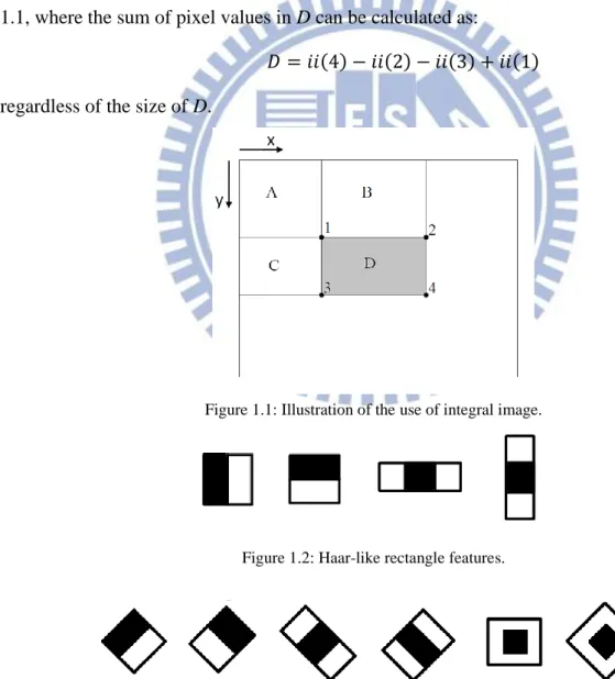
image, one can efficiently compute the sum of pixel values in a rectangle, as shown in Figure
1.1, where the sum of pixel values in D can be calculated as:
( ) ( ) ( ) ( ) (2) regardless of the size of D.
Figure 1.1: Illustration of the use of integral image.
Figure 1.2: Haar-like rectangle features.
So we can compute simple Haar-like rectangle feature by using the integral image, as shown
in Figure 1.2. The feature value is the intensity difference between black and white rectangles.
Afterwards lots of research works improve the Haar-like rectangle features. In [2]、[3],
the authors rotate these features by 45 degrees, and use center-surround feature, as shown in
Figure 1.3. The integral image rotated by 45 degrees in [2]、[3] is calculated as follow:
( ) ∑ | | ( ) (3) Using the rotated integral image, we can compute the sum of pixel values in any rotated
rectangular area, as shown in Figure 1.4. The sum of pixel values in D can be calculated as:
( ) ( ) ( ) ( ) (4) So we can compute simply rotated Haar-like rectangle feature by using the rotated integral
image in Figure 1.3. The authors in [2] say that using rotated rectangle feature can improve
the performance by about 10%.
Figure 1.4: Illustration of the rotated integral image.
Jones and Viola [4] build diagonal filters which focus on diagonal structures in the image.
These diagonal filters are shown in Figure 1.5. The sum of the pixel values in the dark gray
shaded region is subtracted from the sum calculated from the light gray shaded region. To
compute the diagonal filters, they just use 16 pixels in the corners. These diagonal features are
Figure 1.5: The two basic types of diagonal filters [4].
Three types of Haar wavelet like features are defined in the detection sub-window in [5],
as shown in Figure 1.6. The rectangles are of flexible size and are at distances of ( ) apart. These features can be non-symmetrical to cater to non-symmetrical characteristics of non-frontal faces.
Figure 1.6: Haar wavelet like features with flexible sizes and distances [6].
In addition to designing different features, there is another way to improve the detected
performance by using better boosting learning algorithm. In [1], Jones and Viola use
AdaBoost learning algorithm which selects a small number of Haar-like features from a larger
set and yields extremely efficient classifiers. Based on [2], Li et al. in [5] use FloatBoost
which includes the idea of Floating Search [6] into AdaBoost to overcome the
non-monotocity problems associated with AdaBoost. According to [6], FloatBoost only needs
1.2.2
Face detection in nighttime
Different from daytime, face detection in nighttime is limited by the lack of light. We
can’t find where the face is in the images. To solve the light problem in nighttime, most of researchers use the near infrared (NIR) camera to get the images or videos.
In [7], Zhao and Grigat present an automatic face recognition system in the near IR
spectrum. They use a simple and low cost hardware to get the “Bright pupil” effect which is
utilized to localize the eyes, as shown in Figure 1.7. Then Discrete Cosine Transform (DCT)
coefficients are selected as features, and Support Vector Machines (SVM) are employed to
identify faces.
Figure 1.7: Some examples of images with “Bright pupil” effect.
J. Dowdall et al. [8] use the NIR skin detection to obtain the skin region of human being,
and then use two distinct modes for face detection. In the first mode, they use correlated
multiband integral projections to detect the eyes and the eyebrows. Their system enters the
second mode if face detection fails in the first mode. Facial feature detection in the second
mode is based on a dynamic thresholding model and template matching.
In [9], the authors present an active NIR imaging system which is capable of producing
face images of good condition regardless of visible lights. Two statistical learning algorithms,
one is based on LDA and, the other on AdaBoost, are used to build face recognition
1.2.3
Multi-intensity IR illuminator
In [10], a new multi-intensity IR illuminator (MIIR-illuminator) is developed for
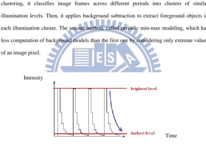
reducing blurred imaging results for nighttime surveillance. As shown in Figure 1.8, the
illumination intensities are changed periodically from the brightest level to the darkest one. In
[11], two methods of foreground object detection are developed for video sequences captured
with the MIIR-illuminator. The first method is background modeling based on illumination
clustering, it classifies image frames across different periods into clusters of similar
illumination levels. Then, it applies background subtraction to extract foreground objects in
each illumination cluster. The second method, called periodic min-max modeling, which has
less computation of background models than the first one by considering only extreme values
of an image pixel.
Figure 1.8: Periodic changes of the illumination intensities of a MIIR-illuminator.
In [12], the authors use MIIR-illuminator to detect license plate in nighttime scenes.
Figure 1.9 illustrates the schematic of the framework. Potential locations of the license plates
are estimated using the gradient and edge features, and then verified based on the stroke width
of the license ID. Finally, the results of license plate detection obtained from images captured
with different illumination levels are integrated into a synthesized image of high dynamic
range for better visualization.
Time Intensity
Figure 1.9: Schematic diagram of the framework from [12].
With the MIIR-illuminator, human faces are far away from the camera can be observed
in high illumination levels while the faces close to the camera aren’t be overexposure in low
illumination levels. We use MIIR-illuminator to capture surveillance video, and design an
effective algorithm to pick out the human faces in these images.
1.3 Organization of thesis
In nighttime surveillance, it is important to capture people in video sequences, especially
human faces. The advantage which MIIR-illuminator emits different intensity infrared light
periodically can let us get more information from nighttime environment. So, we use the face
detection techniques by Viola and Jones to detect human faces in the images captured by
MIIR-illuminator. In addition, selecting the high quality (HQ) faces is also important in
nighttime surveillance. The definition of HQ faces is the selected faces which are seen clearly
for human eyes, not overexposure or underexposure. We design a method for face image
selection.
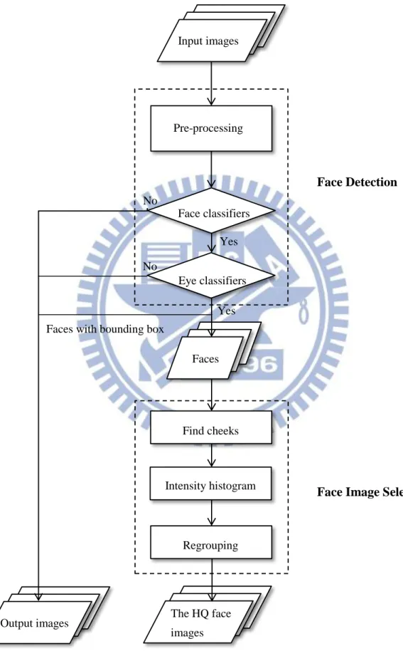
The flowchart of this thesis is shown in Figure 1.10. In the remainder of this thesis, a
review of MIIR-illuminator is described in detail in Chapter 2. In Chapter 3, we elaborate on
selection is described clearly. In Chapter 5, experimental results under different environments
are described in detail. Finally, we give conclusions and discuss future works in Chapter 6.
Figure 1.10: Flowchart of this thesis. Input images Pre-processing Face classifiers Eye classifiers Faces Find cheeks Intensity histogram Regrouping The HQ face images Output images Face Detection
Face Image Selection
No
Yes
Yes No
Chapter 2. The Multi-Intensity IR
Illuminator
Currently, nighttime surveillance is generally performed under a constant intensity of IR
illuminator. Therefore, only few locations could be well-illuminated. People at far distances
from a camera may hard to be recognized due to the limited power of IR-illuminator. On the
other hand, people close to a camera may become unclear due to overexposure of the image
under the high intensity from an IR-illuminator. These problems cause low quality problem of
nighttime video. In order to solve these problems, we use MIIR-illuminator to expand the
range of nighttime surveillance, which will be described in this chapter together with some
special features of images thus captured.
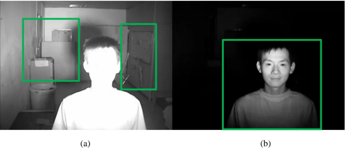
2.1 MIIR-illuminator device
MIIR-illuminator has the capabilities of emitting multi-intensity of IR light by changing
the intensity periodically. It can let the camera capture more information from surveillance
depths and widths, as shown in Figure 2.1. In Figure 2.1(a), we can see the detailed
information about refrigerator and whiteboard, which are far from the camera, with the
brightest illumination level. In Figure 2.1(b), we can see the human face, which is close to the
(a) (b) Figure 2.1: Camera captures different ranges of surveillance depth.
Authors in [10] controls the light emitted by MIIR-illuminator to change periodically
from the brightest intensity to the darkest intensity. Figure 1.8 already shows the periodic
changes of the illumination intensities of a MIIR-illuminator and Figure 2.2 verifies the
periodic changes of the illumination intensities from oscilloscope. The frequency is 15 hertz
and each cycle has six illumination levels.
Figure 2.2: Intensity waveform of MIIR-illuminator detected by photodiode which is displayed on an oscilloscope.
2.2 Features of images captured with MIIR-illuminator
Images captured using the MIIR-illuminator look quite different from those obtained by
traditional IR illuminators because the brightness of the former changes periodically. Some
features of images captured with MIIR-illuminator will be described in this section.
2.2.1
Brightness change is not perfectly periodic
The multi-intensity illumination levels in each cycle are not exactly the same, as shown
in Figure 2.3 for the distribution of average intensity of an image with only a background of
white wall. In this thesis, average intensity is defined as spatial average of total exposed
image, and the formula is defined as,
∑ ∑ ( ) (5)
where is average intensity, is the image height, is the image width, and ( ) is the pixel value. In Figure 2.3, there are six illumination cycles, but the shapes of them are not
exactly the same. On the other hand, it is possible to capture totally the same images in a
cycle when the time to transport images to the storage is not enough. Therefore, these
redundant images shall be deleted for improving the performance of computation, and then
we can do face detection and subsequent selection of high quality human faces.
Frame number Intensity
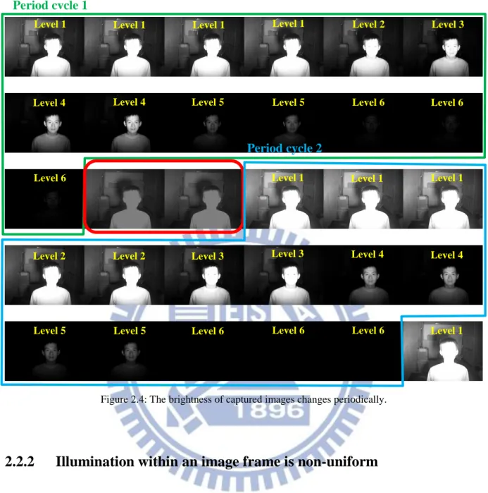
Figure 2.4 shows an example to illustrate above situation. There are two cycles of images
captured with MIIR-illuminator, cycle 1 is represented by green block, and cycle 2 is
represented by blue block. Figure 2.4 shows that the illumination levels change periodically
from the brightest intensity to the darkest one; however, if the light changes from the darkest
intensity to the brightest one, it is too dark to focus on objects initially and getting poor image
quality. The number of images in the two cycles is not the same. And in each cycle, the
number of image under different illumination levels is also different. In addition, the
illumination level should change from the darkest level of current cycle to the brightest level
of the next cycle. Some transitive images appeared between the two cycles are shown in
Figure 2.4 marked with a red rectangle.
Based on results described above, we can get the conclusion that period of brightness
change is unstable. The redundant and transitive images are not needed. The solution of this
Figure 2.4: The brightness of captured images changes periodically.
2.2.2
Illumination within an image frame is non-uniform
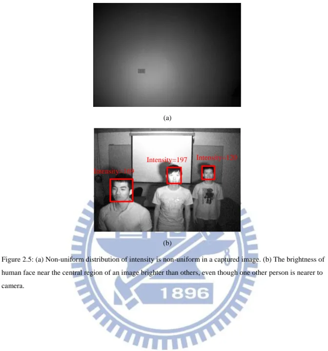
The main feature of image captured with IR illuminator is that the peripheral region of it
is darker than the central region, as shown in Figure 2.5(a). The brightness of human face in
the central region may be brighter than the peripheral region even if distance is farther, as
shown in Figure 2.5(b). The man standing in the middle from camera has highest brightness
of faces in these three men. Due to the non-uniform characteristics of IR illumination, the
brightest object may be not the nearest one. People may not be detected when they pass by the
corner because the peripheral region of image is not bright enough.
Level 1 Level 1 Level 1 Level 1
Level 1 Level 1 Level 1 Level 2 Level 2 Level 2 Level 3 Level 3 Level 3 Level 4 Level 4 Level 4 Level 4 Level 5 Level 5 Level 5 Level 5 Level 6 Level 6 Level 6
Level 6 Level 6 Level 6 Level 1
Period cycle 1
(a)
(b)
Figure 2.5: (a) Non-uniform distribution of intensity is non-uniform in a captured image. (b) The brightness of human face near the central region of an image brighter than others, even though one other person is nearer to camera.
Intensity=197 Intensity=120
Chapter 3. Face Detection for Different
Image Brightness
This chapter introduces how to perform the face detection of images captured with
MIIR-illuminator so that clear faces, which may be critical in law enforcement applications,
may be acquired. We first develop the pre-processing that will delete the previously
mentioned redundant images and transitive images in Section 3.1. We then describe the
principle of face detection approach implemented in OpenCV in Section 3.2. Finally, we
introduce the classifiers that are used in this thesis and show how these classifiers work in
Section 3.3.
3.1 Pre-processing
Because the captured images using MIIR-illuminator have many redundant images, we
need to delete them to avoid unnecessary computation. As shown in Figure 3.1, the images
crossed by red lines are redundant images, which reveal that almost half of images are not
Removing the redundant images can be achieved by evaluating temporal difference of
two consecutive images (t and t-1), and calculates the sum value (diff) of differences as
∑ ( ) (6) where ( ) is the value of pixel i of frame t (t-1). If the sum is zero, it means that
these two continuous images are exactly the same, and we will delete one of the redundant
images.
The transitive images, which are marked with a green rectangle in Figure 3.1, should be
also deleted because they do not belong to any cycle. To that end, we evaluate the total gray
value as for frame t. as
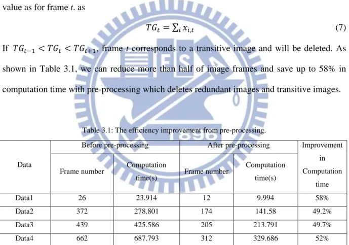
∑ (7) If , frame t corresponds to a transitive image and will be deleted. As shown in Table 3.1, we can reduce more than half of image frames and save up to 58% in
computation time with pre-processing which deletes redundant images and transitive images.
Table 3.1: The efficiency improvement from pre-processing.
Data
Before pre-processing After pre-processing Improvement in Computation
time Frame number Computation
time(s) Frame number
Computation time(s) Data1 26 23.914 12 9.994 58% Data2 372 278.801 174 141.58 49.2% Data3 439 425.586 205 213.791 49.7% Data4 662 687.793 312 329.686 52%
3.2 Review of face detection
This section describes the face detection in OpenCV which include: (1) Haar-like
features and integral image, (2) AdaBoost algorithm for training classifier, (3) cascade of
classifiers. The approach is based on [1] by Viola and Jones.
Haar-like features are shown in Figures 1.2, and 1.3, and can be computed very rapidly
using integral image. The formulas which calculate the simple Haar-like features and rotated
Haar-like features are described in Section 1.2.1. The main advantage of using the integral
image is that any rectangular sum can be computed in four array references. Two-rectangle
features can be computed with six references because the two rectangles are adjacent.
Similarly, three- and four-rectangle features only need eight and nine references, respectively.
AdaBoost is an efficient boosting algorithm for training classifier. It selects good features from a large feature set. It constructs weak classifiers, each of which is based on one
of the features. Then, AdaBoost will boost (via weighted summation) the weak classifier into
a stronger classifier. Cascade of classifiers achieves higher detection performance and less
computation time. Connecting many classifiers in series will create a cascade of classifier that
separates positive or negative data, as shown in Figure 3.2. Simpler classifiers are used to
reject the majority of sub-windows at earlier stages before more complex classifiers.
Figure 3.2: A cascade of classifiers with N stages. Each classifier is trained to achieve a hit rate of h and a false alarm rate of f. N 3 2 1 1-f h h h h 1-f 1-f 1-f
Sub-windows … Classified faces
3.3 Face detection using two-layer classifiers
According to Section 3.2, frontal face detection by Viola and Jones [1] is simple and
effective. R. Lienhart et al. [3] then use modified Haar-like feature and Gentle AdaBoost
algorithm to improve hit rate of face detection, with the performance raised up to 82.7% at a
rescale factor of 1.1. This is a good approach for frontal face detection so we apply the
classifier as our first-layer classifier. By the way, we do try to build our classifier but the
result is worse than theirs, as shown in Figure 3.3. In Figure 3.3 (a) – (d), both the results of
(a)
(b)
(c)
(d)
Figure 3.3 (a) – (d): The results of using different classifiers. On the left, red rectangles are for face detected by frontal face classifier described in [3]. On the right, red rectangles are for faces detected by ours frontal face classifier.
The purpose of this thesis is to capture HQ human faces. According to our observation,
some of the faces which are detected by the frontal face classifier are not clear enough. The
facial features may be overexposed or blurred, as shown in Figure 3.4. In order to remove
blurred faces and wrong faces, we use two layers of classifiers to double check clear human
faces.
Figure 3.4: Examples of overexposed and blurred faces.
To that end, in addition to the first layer classifier which is the frontal face classifier
mentioned in previous paragraph, we use a second layer classifier to process the candidate
regions which is identified by the first layer classifier. We tried to use nose, mouth, one eye
and eye pair classifiers in OpenCV to be the second layer classifier. The results show that the
eye pair classifier gets lowest false alarm, as shown in Table 3.2, so we choose the eye pair
classifier which is trained by M. Castrillo´n et al [13] to be the second layer classifier. The
miss rate of the eye pair classifier is 35.2%, which is also the lowest.
Table 3.2: The accuracies of different second layer classifiers. Classifier Detected
region TP FN FP TN Miss rate
Eye pair 344 191 104 0 49 35.2%
Eye 344 97 198 5 44 67.1%
Nose 344 158 137 9 40 46.4%
Figure 3.5 shows the results of facial features detection obtained with different classifiers.
The red rectangle regions are detected as human faces by the frontal face classifier, and the
green rectangle regions are detected as their facial features by the second layer classifier. It is
(a) (b) (c) (d) (e) (f)
Figure 3.5 : The red rectangle regions are the results of first layer classifier and the green rectangle regions are the results of different second layer classifiers. The latter (from left to right): eye pair classifier, eye classifier, nose classifier, and mouth classifier.
The above captured human face images with multi-intensity illumination are clear at
different distances. Based on these images, correct human faces can often be detected by
two-layer classifiers. As shown in Figure 3.6(a), when the man walks from far to near, his
face at different distances can be captured by adopting different illumination levels. On the
other hand, Figure 3.6(b) shows four people at different distances, with their faces captured at
different illumination levels in an illumination cycle. The person who stands at the farthest
distance from camera can be captured with the first or second brightness level, wherein the
people standing closer to the camera are overexposed. When the intensity is lower, the man
standing closer to the camera is clear and the human face images can be captured easily. The
man who stands closest to camera is detected easily in images with darker levels while others
are underexposed.
…
…
(a)
Level 1 Level 2 Level 3 Level 4 Level 5 Level 6
Level 1 Level 2 Level 3 Level 4 Level 5 Level 6
(b)
Figure 3.6: Human faces at different distances can be captured by adopting different illumination levels.
After the above face detection procedure, we can get multiple images of human face for
each person. A method to select human face images of good quality for further processing
will be described in detail in the next chapter.
Level 1 Level 2 Level 3
Chapter 4. Face Image Selection by Using
Intensity Histogram
For human faces detected by the two-layer classifier described in the previous chapter, as
shown in Figure 4.11, we need to select the high quality (HQ) ones for better visualization. In Section 4.1, we explain the reason of choosing the cheek region of human face for the above
selection by examining the gray value distribution for a face. Accordingly, the intensity
histogram of cheek region is calculated for getting the representative intensity of human faces
in Section 4.2. Finally, the method of regrouping human faces with different brightness for
better visualization is described in Section 4.3.
Figure 4.1: Human faces detected by the two-layer classifier.
1. Figure 3.6(a) shows selected images of three illumination cycles of the same image sequence.
4.1 Using cheek portion of human faces
One possible way of selecting HQ faces from human faces detected by the two-layer
classifier described in the previous chapter is to analyze the brightness of a human face. As
shown in Figure 4.2(a), if the brightness of face is too high, the facial features will be unclear
(1) (2)
(3) (4)
since the image is overexposed, similar problem will also occur when the image is
underexposed, as shown in Figure 4.2(c). On the other hand, for the face image shown in
Figure 4.2(b), its brightness is close to that desired for a HQ face in that all the facial features
have good contrast and can be identified easily.
(a) (b) (c)
Figure 4.2: Some examples of different brightness of face. (a) High brightness. (b) Medium brightness. (c) Low brightness.
In order to establish an appropriate and consistent measure of brightness of human face,
we first analyze the brightness distribution of detected face images. For easier observation, we
divide the gray values between 0 and 255 into 8 portions and use 8 different colors to
represent them. For example, Figure 4.3(a) shows face images detected by the two-layer
classifier, with gray values illustrated with the above colors shown in Figure 4.3(b). In Figure
4.3(b), one can see that the color of human cheek has near uniform distribution, which has
spatially smooth surface with uniform texture, and occupies a larger portion of human face.
Therefore, we choose the brightness of cheek to represent the brightness of face. A simple
way of cutting the cheek region, which is adopted in the thesis, is shown in Figure 4.4. We cut
the top half, one-sixth of bottom, and one-sixth of left and right so that the region inside the
green rectangle is regarded as the cheek portion of human face. Then, we use this cheek
(a)
(b)
Figure 4.3: (a) Original faces which are detected by the two-layer classifier in one illumination cycle. (b) The colors represent different ranges of gray values of a face.
Figure 4.4: The cheek region (green rectangle) used to represent the brightness of human face.
4.2 Calculating the brightness of cheeks
For the cheek region defined above, we now use the intensity histogram as those shown
in Figure 4.5 to obtain a numeric value to represent the brightness of the human face. In
particular, for each of intensity histogram of a check region, we first identity the gray values
of the top ten bins, then calculate the mean value of these bins to represent the brightness of
cheek numerically. 1/6 w 1/6 w l w 1/2 l 1/6 l
Figure 4.5: Some examples of intensity histograms of cheek regions.
Consider a person located at different distances from a camera and illuminated by the
multi-intensity IR illuminator, as shown in Figure 3.6(a), the change of the brightness of the
human face will depend on the distance as well as the light intensity. Figure 4.6 shows the
variation of brightness of the cheek region obtained for such an image sequence in which a
man is walking from far distance to a nearer distance. At first, the brightness of cheek is lower
than 150 for all brightest illumination levels. Then, the brightness in the maximum brightness
level increases gradually, while the difference between maximum and minimum brightness
levels also becomes larger. At last, in the third row of Figure 3.6(a), the man is near the
MIIR-illuminator so that the maximum brightness of face is close to 250 and the human face
is overexposed.
Figure 4.6: The variation of brightness of the cheek region (see text). Brightness
4.3 Regrouping human faces with different brightness
Since the brightness of cheek changes for different illumination levels and at the
different distances, we can’t select the HQ faces in a single illumination level. Thus, we need
to analyze the brightness of all the faces and define the ranges of brightness which can be
used to select the HQ faces.
For the image sequence shown in Figure 3.6(a), 63 human faces are detected from the
174 images which have different brightness and different scales. We then select the clear
faces by hand, as shown in Figure 4.1, for part of 63 human faces with red retangle indicate
the selected ones. Figure 4.7(a) and (b) show intensity histograms of these face images and
the corresponding cheek regions, respectively. While the black backgorund will affect the
determination of the brightness of face images, as shown in Figure 4.7(a), the histogram of
cheek regions more similar to each other faces and will be adopted to calculate the brightness
of these face images. For the HQ faces shown in Figure 4.1 which are selected manually, the
brightness of them are calculated as between 170 and 210, as shown in Table 4.1.
(a)
(b)
Figure 4.7: (a) Histograms of HQ face images. (b) Histograms of cheek regions. Table 4.1: Histograms of HQ faces and their cheek.
(1) (2) (3) (4) (5) (6)
Size 56x56 57x57 62x62 62x62 66x66 70x70
In addition, we also select the human faces with good contrast which are a little brighter
than HQ faces (called Lighter face), and those a little darker than HQ faces (called Darker
faces). Figure 4.8 shows the HQ face, the Lighter face, and the Darker face, all selected
manually.
Figure 4.8: The selection of faces with acceptable quality in one illumination cycle.
Like the brightness range obtained for the HQ faces, similar ranges can also be obtained
for the Lighter faces and the Darker ones as
( ) { ( ) ( ) ( ) (8)
Figure 4.9(a) shows the three groups of face images selected according to (8) wherein the
faces are resized to 50x50 for convenient observation. Moreover, for each group of images,
the brightness of faces are adjusted so that the mean value of image brightness is equal to the
mid-point of the range shown in (8).As shown in Figure 4.9(b), the brightness of all faces in
each group becomes more uniform, and look nicer, after these processing steps. It is not easy
to see that human faces in each group, with same size and similar brightness, are actually
obtained with different illumination levels, and for people located at different distances. Intensity: 248 248 238 180 113 45
1 2 3 4 5 6
(a)
(b)
Figure 4.9: The (a) Size and (b) brightness adjustments of each image group: HQ (top), darker (middle), and lighter (bottom).
Chapter 5. Experimental Results
5.1 Environment settings
Our system includes an IR camera and the MIIR-illuminator which emits six levels of
infrared light periodically, and the IR camera captures image frames with 640x480 in
resolutions. These devices are located about 2 or 2.5 meters above the ground level, as shown
in Figure 5.1.
(a) (b)
Figure 5.1: (a) Experimental environment. (b) Close-up view of IR camera and MIIR-illuminator.
2.5m
MIIR-illuminator IR camera
5.2 Experiment 1 — MIIR-illuminator vs. Traditional IR
illuminator
The purpose of this experiment is to compare the performance of face detection using
MIIR-illuminator and traditional IR illuminator. Figure 5.2 shows face images captured using
the MIIR-illuminator (left column) and a traditional IR illuminator (right column). In Figure
5.2(a), the man is about 4 meters away from the camera. The first illumination level of
MIIR-illuminator is chosen because the image of human face is most clear. However, we
can’t detect the human face in the image illuminated by the traditional IR illuminator at the same distance because the face image is underexposed when the person is far away from the
illuminator. In Figure 5.2(b), images are captured at a distance of 3 meters away from the
camera. Faces can be detected from both images. In Figure 5.2(c), when the person is 1 meter
away from camera, a good image (under the illumination of level 5) can be selected for the
MIIR-illuminator, shown as the left hand side of Figure 5.2(c); on the right hand side, the
image obtained from traditional IR illuminator is overexposed because the person is too close
to the camera.
Based on these results, one can see that the MIIR-illuminator has better chance of
providing images of high quality for nighttime surveillance of a large area. In particular, we
can capture human faces of better quality for people located at different distances by using
(a)
(b)
(c)
Figure 5.2 (a) – (c): Face images captured using the MIIR-illuminator (left column) and a traditional IR illuminator (right column).
Level 3 Level 1
5.3 Experiment 2 — Face detection by using MIIR-illuminator
under simple background environments
This section presents some experimental results of face detection by using
MIIR-illuminator under simple background environments. The goal of these experiments is to
show that human faces at different distances can be detected correctly from images
illuminated by the MIIR-illuminator before the HQ face images can be selected from them.
The experiments can be divided into (i) single person case and (ii) multi-person case.
5.3.1
Single person under simple background environments
The camera is installed at 2 meters above the ground for this experiment wherein man is
walking from far to near slowly, as shown from left to right and from top to bottom in Figure
5.3(a). Image obtained with six different illumination levels within one illumination cycle are
displayed in each row. In the first row of Figure 5.3(a), the faces can only be detected under
the brightest illumination levels (levels 1 and 2) and underexposed under other illumination
levels. In the second row, the faces can only be detected under the medium illumination levels
(levels 2 - 5) and either overexposed or underexposed under other illumination levels. In the
third row, these faces can only be detected under the darkest illumination levels (levels 3 - 6).
As shown in Figure 5.3(b), the faces of better quality can be further divided into 3 groups,
namely the Best group, the Lighter group, the Darker group, and the Other group. The human
faces in the first row correspond to the HQ face images, with highest quality and good
contrast. For each group, after size and brightness adjustments, the face images which are
captured for person walking at different distances are very similar to one another. While the
Lighter and Darker groups also have acceptable quality of facial features, the Other group are
…
…
(a)
(b)
Figure 5.3 : Results of face detection and face image selection under simple background environments.
(a) The human faces are captured under six different illumination levels. (b) The faces of better quality can be further divided into 3 groups.
Best group
Lighter group
Darker group
Other group
Level 1 Level 2 Level 3 Level 4 Level 5 Level 6
Level 1 Level 2 Level 3 Level 4 Level 5 Level 6
5.3.2
Multi-person under simple background environments
The camera is installed at 2.5 meters above the ground for this experiment wherein two
men are walking along with one behind the other, as shown in Figure 5.4(a). Image obtained
with six different illumination levels within one illumination cycle are displayed in each row.
In the first row of Figure 5.4(a), faces can only be detected under highest illumination levels
(levels 1 and 2) and underexposed under other illumination levels. Compared with the first
row, the closer person is close enough to be detected under five different illumination levels
in the second row of Figure 5.4(a). In the third row of Figure 5.4(a), the closer person is too
close and overexposed under the brighter illumination levels, but we still can detect human
faces under lower illumination levels (levels 3, 4, and 5). In the same row, the distant person
can only be detected under the highest illumination level; however, the front one is
overexposed.
Figure 5.4(b) shows results of face image regrouping, similar to that shown in Figure
5.3(b). One can see that multiple face images of seemingly equal quality can be obtained for
each group of images, and it requires careful examination to tell that these images are actually
obtained for people located at different distances from the camera.
According to this experimental result, our methods of face detection and face image
…
…
(a)
(b)
Figure 5.4 : Results under multi-person condition. (a) Results of face detection. (b) Results of face image selection.
Best group
Lighter group
Darker group
Other group
Level 1 Level 2 Level 3 Level 4 Level 5 Level 6
Level 1 Level 2 Level 3 Level 4 Level 5 Level 6
5.4 Experiment 3 — Face detection by using MIIR-illuminator
under complex background environments
This section presents some experimental results of face detection by using
MIIR-illuminator under complex background environments. The goal of these experiments is
to show that human faces at different distances can be detected correctly even under complex
background environments before the HQ face images can be selected form them. The
experiments can be divided into (i) single person case and (ii) multi-person case.
The results of face detection under complex background environments cause many false
positive regions if only one-layer classifier applied. As shown in Figure 5.5(a), which may
decrease the accuracy of face detection. Our method which uses two-layer classifiers can filter
(a) (b)
Figure 5.5: (a) Face detection results under simple background and complex background environments obtained by using one-layer classifier. (b) Similar results obtained by using two-layer classifier.
Simple background Complex background
5.4.1
Single person under complex background environments
The camera is installed at 2 meters above the ground for this experiment. As shown in
Figure 5.6(a), image obtained with six different illumination levels within one illumination
cycle are displayed in each row. When the man stands at far distance from the camera, his
face can only be detected under higher illumination levels and underexposed under other
illumination levels. On the other hand, as the man walks towards the camera, the face image is
overexposed under the brightest illumination level, but we can detect it by selecting the image
…
…
(a)
(b)
Figure 5.6: Results of face detection and face image selection for one person under complex background environments. (a) The human face images are captured under six different illumination levels. (b) The results of grouping the detected face images.
Level 1 Level 2 Level 3 Level 4 Level 5 Level 6
Level 1 Level 2 Level 3 Level 4 Level 5 Level 6
Level 1 Level 2 Level 3 Level 4 Level 5 Level 6
Best group
Lighter group
Darker group
5.4.2
Multi-person under complex background environments
The camera is installed at 2 meters above the ground for this experiment. Two persons
walk to the camera one behind the other under complex background environments. As shown
in Figure 5.7(a), image obtained with six different illumination levels within one illumination
cycle are displayed in each row. The face of closer person can be detected under the brighter
illumination levels with far distance condition. When two persons walk towards the camera,
the face of closer person can be detected under the darker illumination level, and the face of
distant person can be detected under the brighter illumination level. According to these
experimental results, the performance of face detection under complex background
…
…
(a)
(b)
Figure 5.7: Results of face detection and face image selection for multi-person under complex background environments. (a) The human face images are detected under six different illumination levels. (b) The results of grouping the detected face images.
Level 1 Level 2 Level 3 Level 4 Level 5 Level 6
Level 1 Level 2 Level 3 Level 4 Level 5 Level 6
Level 1 Level 2 Level 3 Level 4 Level 5 Level 6
Best group
Lighter group
Darker group
Chapter 6. Conclusions and Future Works
6.1 Conclusions
In this thesis, we use MIIR-illuminator for nighttime face detection. The advantage of
using MIIR-illuminator is that it emits infrared light of different intensities periodically,
acquiring more information from the environment. Such an approach seems to reasonably
solve the problem of capturing poor quality images of human faces in nighttime.
Our face detection method is divided into two parts: face detection and face image
selection. The two-layer classifiers of face detection improve the performance of detection by
decreasing the false alarm. The face image selection scheme then selects the HQ faces, with
minor adjustments for better visualization, from the detected human faces. Experimental
results show that HQ face images can be detected and selected for persons at different
distances from the camera. Even under a complex background environment, our method can
still detect and select HQ faces effectively and correctly, which is good for improving the
performance in crime investigation and prevention.
6.2 Future works
Our Face detection method uses the whole image to detect face regions. In the future, we
hope that we can incorporate the foreground detection algorithm [11] as a preprocessing stage
of face detection. It may identify the foreground regions quickly before human faces are
detected within these regions. Hopefully, such an approach, will decrease the computation
time and filter out some false positive regions in the background. In addition, we hope to
establish an objective standard for HQ face images. Finally, we hope that MIIR-illuminator
References
[1] P. Viola and M. Jones, “Rapid Object Detection using a Boosted Cascade of Simple
Features,” Computer Vision and Pattern Recognition, vol.1, pp. 511-518, 2001.
[2] R. Lienhart and J. Maydt, “An Extended Set of Haar-like Features for Rapid Object
Detection,” International Conference on Image Processing, vol. 1, pp. 900-903, 2002.
[3] R. Lienhart, A. Kuranov, and V. Pisarevsky, “Empirical Analysis of Detection Cascades
of Boosted Classifiers for Rapid Object Detection,” Pattern Recognition, pp. 297-304,
2003.
[4] M. Jones and P. Viola, “Fast Multi-view Face Detection,” Technical Report 096,
Mitsubishi Electric Research Laboratories, 2003.
[5] S. Li, L. Zhu, Z. Zhang, A. Blake, H. Zhang, and H. Shum, “Statistical Learning of
Multi-View Face Detection,” European Conference on Computer Vision, pp. 117-121,
2002.
[6] P. Pudil, J. Novovicova, and J. Kittler, “Floating Search Methods in Feature Selection,”
Pattern Recognition Letters, vo1. 15, pp. 1119-1125, 1994.
[7] S. Zhao and R. R. Grigat, “An Automatic Face Recognition System in the Near Infrared
Spectrum,” Machine Learning and Data Mining in Pattern Recognition, pp. 437-444,
2005.
[8] J. Dowdall, I. Pavlidis, and G. Bebis, “Face Detection in the Near- IR Spectrum,” Image
and Vision Computing, vol. 21, pp. 565-578, 2003.
[9] S. Z. Li, R. Chu, S. Liao, and L. Zhang, “Illumination Invariant Face Recognition using
Near-Infrared Images,” Pattern Analysis and Machine Intelligence, vol. 29, no. 4, pp.
627–639, 2007.
[10] W. C. Teng, “A New Design of IR Illuminator for Nighttime Surveillance,” MS Thesis,
National Chiao Tung Univ., 2010.
Multi-Intensity Infrared Illuminator,” International Conference on Signal Processing
and Imaging Engineering, 2011.
[12] Y. T. Chen, J. H. Chuang, H. H. Lin, and H. T. Chen, “Robust License Plate Detection in
Nighttime Scenes using Multiple Intensity IR-Illuminator,” International Symposium on
Industrial Electronics, 2012.
[13] M. Castrillo´n, O. De´niz, C. Guerra, and M. Herna´ndez, “ENCARA2: Real-Time
Detection of Multiple Faces at Different Resolutions in Video Streams,” Journal of

![Figure 1.6: Haar wavelet like features with flexible sizes and distances [6].](https://thumb-ap.123doks.com/thumbv2/9libinfo/8243072.171400/14.892.132.813.394.799/figure-haar-wavelet-like-features-flexible-sizes-distances.webp)
![Figure 1.9: Schematic diagram of the framework from [12].](https://thumb-ap.123doks.com/thumbv2/9libinfo/8243072.171400/17.892.288.653.116.365/figure-schematic-diagram-framework.webp)