國立交通大學
電子工程學系 電子研究所碩士班
碩 士 論 文
可重組化 RSA 密碼系統之設計與實作
Design and Implementation of
Reconfigurable RSA Cryptosystems
研究生:陳允律
指導教授:張錫嘉
可重組化 RSA 密碼系統之設計與實作
Design and Implementation of
Reconfigurable RSA Cryptosystems
學生:陳允律 Student : Yun-Lu Chen
指導教授:張錫嘉 Advisor : Hsie-Chia Chang
國立交通大學
電子工程學系 電子研究所碩士班
碩士論文
A Thesis
Submitted to Department of Electronics Engineering & Institute of Electronics
College of Electrical and Computer Engineering
National Chiao Tung University
In Partial Fulfillment of the Requirements
for the Degree of Master
In
Electronics Engineering
July 2006
Hsinchu, Taiwan, R.O.C.
可重組化 RSA 密碼系統之設計與實作
學生 : 陳允律 指導教授 : 張錫嘉
國立交通大學
電子工程學系 電子研究所碩士班
摘
要
本論文提出了在 RSA 密碼系統上可重組化的實作方法。RSA 在許多安
全性的應用上常被使用,像是智慧型卡片。而一造安全性的層級不同,RSA
模數的區塊大小也不盡相同。在大多數的智慧型卡片的應用上,RSA 密碼
系統通常被設計在 512/1024/2048/4096 位元模數區塊大小的加解密下工
作。為了能工作在大多數的智慧型卡片的應用上,本篇論文中的演算法是
在可重組化和縮減面積下由蒙哥馬利模數乘法演算法改進而來,為了縮減
面積,在架構上也利用五個記憶體區塊來減小龐大的暫存器數量。在這樣
的設計之下可利用
Xilinx Vertex2 XC2V8000 的五個記憶體區塊和 6783 個 slices
來達到 512 模數下 99kb/s,1024 模數下 26kb/s,2048 模數下 6.8kb/s,4096
模數下 1.7kb/s。
Design and Implementation of
Reconfigurable RSA Cryptosystems
Student: Yun-Lu Chen
Advisor: Hsie-Chia Chang
Department of Electronics Engineering & Institute of Electronics
National Chiao Tung University
ABSTRACT
This thesis introduces a reconfigurable approach to the hardware implementation of the RSA cryptosystem. RSA is a well used algorithm in many security applications, such as smart card. The modulus block sizes are different for different level of security. For the majority applications of smart card, the RSA cryptosystem would be designed to work with 512/1024/2048/4096-bit RSA encryption/decryption. The algorithm of this thesis is modified by the Montgomery modular multiplication algorithm to be reconfigurable and reduce area. In order to reduce area, there are five memory blocks to substitute the large amount of registers. As such the design can used five memory blocks and 6783 slices to achieve the baud rate of 99kb/s for 512-bit modulus, 29kb/s for 1024-bit modulus, 6.8kb/s for 2048-bit modulus and 1.7kb/s for 4096-bit with Xilinx Vertex2 XC2V8000.
誌
謝
要完成一本論文,除了作者本身的努力與付出,旁人的幫助也是不可或缺的。 在研 究生的學涯裡我的指導教授張錫嘉博士無論是在研究方面、工作方面,亦或是生活方 面,無不給予作者極大的幫助,研究方面像嚴師,工作方面像前輩,生活方面像朋友, 這就是老師給我的感覺,真的是非常感謝老師。再來要感謝的就是林建青學長,每當我 遇到問題時,學長總是不厭其煩的幫我解答,讓我在研究的路上,能更加的順暢。 此外,當然也要感謝我的家人,無論是在精神上或是物質上給予的支持,使我可以無 後顧之憂完成學業,最後也要感謝 OASIS 和 SUN 實驗室的同學、學弟們,沒有你們,這 段時光不會如此值得回憶,僅以此篇論文與你們共同分享這份喜悅。
Contents
1 Introduction 1 1.1 Secret-key Cryptosystem . . . 3 1.2 Public-key Cryptosystem . . . 4 2 RSA Cryptosystem 8 2.1 Mathematics Foundation . . . 8 2.1.1 Number Theory . . . 8 2.1.2 Montgomery’s Method . . . 11 2.2 RSA Algorithm . . . 13 2.2.1 RSA Scheme . . . 13 2.2.2 Modular Exponentiation . . . 15 2.2.3 Modular Multiplication . . . 173 Proposed Reconfigurable RSA Architecture 24 3.1 Overview of the Proposed Architecture . . . 24
3.1.1 I/O Description . . . 24
3.1.2 Main Modules Description . . . 26
4 Implementation 34 4.1 Implementation with cell base design . . . 34 4.2 Implementation on FPGA . . . 36 5 Conclusion 37
List of Figures
1.1 Information Communication Model . . . 2
1.2 Secret-key Cryptosystem Model . . . 3
1.3 Public-key Cryptosystem Model . . . 5
1.4 Public-key Cryptosystem Model with Digital Signature . . . 6
3.1 I/O pins of the proposed RSA cryptosystem . . . 25
3.2 Block diagram of proposed RSA cryptosystem . . . 26
3.3 Processing Element used in figure. 3.4 . . . 27
3.4 Processing Element Array and FIFO . . . 28
3.5 Load mode type . . . 30
3.6 Configuration completion . . . 31
3.7 Correct output data stored . . . 32
3.8 Read correct output data . . . 33
List of Tables
3.1 Mode Type . . . 31 4.1 The synthesized results with cell base design . . . 35 4.2 The verification results on FPGA . . . 36 5.1 Comparison with other 1024-bits implementations with cell base
de-sign . . . 38 5.2 Comparison with other 512-bits implementations on FPGA . . . 39 5.3 Comparison with other 1024-bits implementations on FPGA . . . 39
Chapter 1
Introduction
As time goes on, the internet has become as popular as possible. The communica-tion between people and people is originally need face-to-face, but can carry on the remote communication with some tools now. The convenient means of communica-tion are depended on the prosperity of the internet. People depend on the internet sending message that may be secret or important. If the hacker gets the message which has no protector, the secret is not secret. Informant security is more and more important in the internet age.
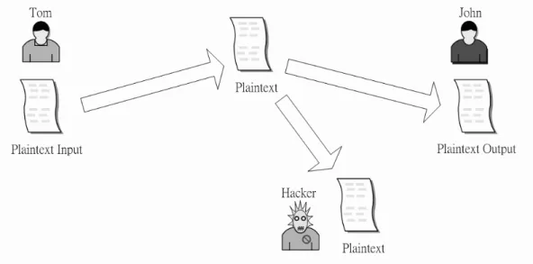
Cryptography [1] is a knowledge to research how to avoid that the hacker gets the real message. As the increase of the computer performance, there are much difference between conventional and modern cryptography. For the general infor-mation communication model that is shown in Fig. 1.1, there are the sender, receiver and hacker. Before beginning, we define some terms. The original intelligible mes-sage that the sender sends is known as the plaintext. The coded mesmes-sage that has scrambled by cryptosystem is called the ciphertext. Reversibility is the fundamental need for the cryptosystem. Generally speaking, the cryptosystem supply following functions to depend on the application.
Confidentiality : It is to avoid that the hacker gets plaintext.
Figure 1.1: Information Communication Model .
Integrity : It is to know that the message has been modified in transmission or not.
Nonrepudiation : It can prevent either sender or receiver from denying a trans-mitted message.
There are two kinds of commonly used encryption/decryption ways: 1. Conventional: Secret-key encryption/decryption
2. Modern: Public-key encryption/decryption
The conventional cryptography usually focus on the confidentiality of the in-formation, but the modern cryptography also considers that the authentication, integrity and nonrepudiation of the information are more important for the appli-cation of the commerce.
Figure 1.2: Secret-key Cryptosystem Model .
1.1
Secret-key Cryptosystem
In conventional cryptography, there is a key pair E,D. Usually, the key E and the key D are the same, or it is easy to find one if another is known. A secret-key cryptosystem model is shown in Fig. 1.2. The sender uses the key E to encrypt the plaintext, and the receiver uses the key D to decrypt the ciphertext. This method is known as secret-key or symmetric cryptosystem. All secret-key cryptosystems are based on substitution and transposition. Substitution is mean mapping from one field to anther and transposition is mean replace the element of the message. Because of that the hardware of substitution and transposition is very easy, secret-key cryptosystem is much faster than public-secret-key cryptosystem in general. There are many algorithms proposed for the secret-key cryptosystem, such as DES(Data Encryption Standard) and AES(Advanced Encryption Standard).
A secret-key cryptosystem has several drawback listed below:
• How to manage the keys when the number of key pairs is large?
– If there are n subscribers in a network, then everyone have to hold n − 1 keys to communicate with others. For example, If there are 1000
sub-scribers in a network, then the number of key pairs is 499 × 500. It is too hard to manage such many key pairs.
• How to get the key pair between the sender and receiver?
– A secure channel is needed between the sender and receiver who have never meet before, but how to get this channel? This problem is called the key distribution problem.
• How to ensure the Authentication and Nonrepudiation?
– In symmetric cryptosystem, the sender and receiver both have the same key for encryption and decryption. Thus the sender may deny sending the message that has sent before because it is impossible to ensure that the message is not make by the receiver.
1.2
Public-key Cryptosystem
The concept of public-key cryptography evolved from an attempt to solve the prob-lems of symmetric encryption. Public-key algorithms rely on one key for encryption and a different but related key for decryption. These algorithms have the following important characteristic.
• It is computationally infeasible to determine the decryption key given only
knowledge of the cryptographic algorithm and the encryption key. In addition, some algorithms also exhibit the following characteristic.
• Either of the two related keys can be used for encryption, with the other used
for decryption.
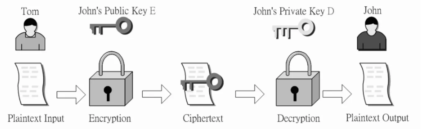
Figure 1.3: Public-key Cryptosystem Model .
C = EC(EJ, M )
M = DC(DJ, C)
A secure communication using a public-key cryptosystem is shown in Fig. 1.3, and the essential steps are the following:
1. Each user generates a pair of keys to be used for the encryption and decryption of messages.
2. Each user places one of the two keys in a public register or other accessible file. This is the public key. The companion key is kept private. Each user maintains a collection of public keys obtained from others.
3. If Tom wishes to send a confidential message to John, Tom encrypts the mes-sage using John’s public key.
4. When John receives the message, he decrypts it using his private key. No other recipient can decrypt the message because only John knows John’s private key. In this approach, all participants can access to public keys, and private keys are generated locally by each participant and therefore need never be distributed. As
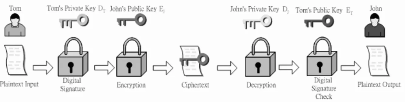
Figure 1.4: Public-key Cryptosystem Model with Digital Signature .
long as a system controls its private key, its incoming communication is secure. At any time, a system can change its private key and publish the companion public key to replace its old public key.
It is important to emphasize that the encryption process just described does not provide confidentiality. That is, the message begin sent is safe from alteration but not from eavesdropping.
The public-key cryptosystem model with digital signature is shown in Fig. 1.4. It is impossible to provide both the authentication function and confidentiality by a double use of the public-key scheme.
S = EC(DT, M )
C = EC(EJ, S)
S = DC(DJ, C)
M = DC(ET, S)
In this case, we begin as before by encrypting a message, using the sender’s private key. This provides the digital signature. Next, we encrypt again, using the receiver’s public key. The final ciphertext can be decrypted only by the intended receiver, who alone has the matching private key. Thus, confidentiality is provided. The disadvantage of this approach is that the public-key algorithm, which is
com-plex, must be exercised four times rather than two in each communication.
Depending on the application, the sender uses either the sender’s private key or the receiver’s public key, or both, to perform some type of cryptographic func-tion. In broad terms, we can classify the use of public-key cryptosystems into three categories:
• Encryption/decryption : The sender encrypts a message with the recipient’s
public key.
• Digital signature : The sender signs a message with its private key. Signing
is achieved by a cryptographic algorithm applied to the message or to a small block of data that is a function of the message.
• Key exchange : Two sides cooperate to exchange a session key. Several
Chapter 2
RSA Cryptosystem
2.1
Mathematics Foundation
2.1.1
Number Theory
In modern cryptosystem, the encryption processes are mathematical operations that turn the input numerical values into output numerical values. The must important mathematical tool is number theory, especially the theory of congruences.
Congruences
One of the most basic and useful in number theory is modular arithmetic, or congruences. Let a, b, n be integers with n 6= 0. If a and b differ by a multiple of
n, a is congruent to b mod n.
a ≡ b (mod n)
It can be rewritten as
a ≡ b + nk
for some integer k Primitive Roots
In general, when p is a prime, a primitive root mod p is a number whose powers yield every nonzero class mod p. There are φ(p − 1) primitive roots mod p. Let g be a primitive root for the prime p.
• If i is an integer, then gi ≡ 1 (mod p) if and only if i ≡ 0 (mod p-1 ).
• If j and k are integers, then gj ≡ gk (mod p) if and only if j ≡ k (mod p-1 ).
Fermat’s Theorem
Fermat’s theorem states the follows:If p is prime and a is a positive integer not divisible by p, then
ap−1 ≡ 1 mod p (2.1)
We know that if all of the elements of Zp, where Zp is the set of integers
{0, 1, ..., p − 1}, are multiplied by a, modulo p, the result consists of all of the
elements of Zp in some sequence. Furthermore, a × 0 ≡ 0 mod p. Therefore, the
(p − 1) numbers {a mod p, 2a mod p,...,(p − 1)a mod p} are just the numbers
{1, 2, ..., (p − 1)} in some order. Multiplying the numbers in both sets and taking
the result mod p yields
1 × 2 × ... × (p − 1) ≡ (a mod p) × (2a mod p) × ... × ((p − 1)a mod p) (p − 1)! mod p ≡ (p − 1)!ap−1
We can cancel the (p − 1)! term because it is relatively prime to p. This yields Equation 2.1.
Euler’s Totient Function
Before presenting Euler’s theorem, we need to introduce an important quantity in number theory, referred to as Euler’s totient function and written φ(n), where
φ(n) is the number of positive integers less than n and relatively prime to n. It
should be clear that for a prime number p,
φ(p) = p − 1
There are two prime numbers p and q, with p 6= q. Then, for n = pq,
φ(n) = φ(pq) = φ(p) × φ(q) = (p − 1) × (q − 1) (2.2)
Euler’s Theorem
Euler’s theorem states that for every a and n that are relatively prime:
aφ(n) ≡ 1 mod n (2.3)
Equation 2.3 is true if n is prime, because in that case φ(n) = (n − 1) and Fermat’s theorem holds. However, it also holds for any integer n. Recall that φ(n) is the number of positive integers less than n that are relatively prime to n. Consider the set of such integers, labeled as follows:
R = {x1, x2, ..., xφ(n)}
Now multiply each element by a, modulo n:
S = {(ax1 mod n), (ax2 mod n), ..., (axφ(n) mod n)}
The set S is a permutation of R, by the following line of reasoning:
1. Because a and xi are relatively prime to n, axi must also be relatively prime
to n. Thus, all the elements of S are integers less than n that are relatively prime to n.
2. There are no duplicates in S. If axi mod n = axj mod n, then xi = xj. Therefore, φ(n)Y i=1 (axi mod n) = φ(n)Y i=1 xi φ(n)Y i=1 axi ≡ φ(n)Y i=1 xi( mod n) aφ(n)× φ(n)Y i=1 xi ≡ φ(n)Y i=1 xi( mod n) aφ(n) ≡ 1 mod n
An alternative form of the theorem is also useful:
akφ(n)+1 ≡ a mod n (2.4)
2.1.2
Montgomery’s Method
In 1985, P. L. Montgomery introduced an efficient algorithm for computing R =
a · b mod n where a, b, and n are k-bit binary numbers. The algorithm is
particu-larly suitable for implementation on general-purpose computers which are capable of performing fast arithmetic modulo a power of 2. The Montgomery reduction algorithm computes the resulting k-bit number R without performing a division by the modulus n. Via an ingenious representation of the residue class modulo n, this algorithm replaces division by n operation with division by a power of 2. This op-eration is easily accomplished on a computer since the numbers are represented in binary form. Assuming the modulus n is a k-bit number, i.e., 2k−1 < n < 2k, let
r be 2k. The Montgomery reduction algorithm requires that r and n be relatively
prime, i.e., gcd(r, n) = gcd(2k, n) = 1. This requirement is satisfied if n is odd. The
Given an integer a < n, we define it’s n-residue with respect to r as
a ≡ a · r mod n
It is straightforward to show that the set
{i · r mod n|0 ≤ i ≤ n − 1}
is a complete residue system, i.e., it contains all numbers between 0 and n−1. Thus, there is a one-to-one correspondence between the numbers in the range 0 and n − 1 and the numbers in the above set. The Montgomery reduction algorithm exploits this property by introducing a much faster multiplication routine which computes the n-residue of the product of the two integers whose n-residues are given. Given two n-residues a and b, the Montgomery product is defined as the n-residue
R ≡ a · b · r−1 mod n
where r−1 is the inverse of r modulo n, i.e., it is the number with the property
r−1· r ≡ 1 mod n.
The resulting number R is indeed the n-residue of the product
R ≡ a · b mod n
since
R ≡ a · b · r−1 mod n
≡ a · r · b · r · r−1 mod n ≡ a · b · r mod n
2.2
RSA Algorithm
The pioneering paper by Diffie and Hellman introduced a new approach to cryp-tography and, in effect, challenged cryptologists to come up with a crypcryp-tography algorithm that met the requirements for public-key systems. One of the first of the responses to the challenge was developed in 1977 by Ron Rivest, Adi Shamir, and Len Adleman at MIT and first published [2] in 1978. The Rivesr-Shamir-Adleman (RSA) scheme has since that time reigned supreme as the most widely accepted and implemented general-purpose approach to public-key encryption.
2.2.1
RSA Scheme
The RSA scheme is a block cipher in which the plaintext and ciphertext are integers between 0 and n − 1 for some n which is usually between 512 and 4096. The flow of RSA is showed as following:
Key Generation
Select p, q p and q both prime, p 6= q
Calculate N and φ(N) N = p × q, φ(N) = (p − 1)(q − 1) Select integer E gcd(φ(N), E) = 1; 1 < E < φ(N) Calculate D D ≡ E−1 mod φ(N)
Public key KU = {E, N }
Private key KR = {D, N }
Encryption
Plaintext M M < N
Ciphertext C C = ME mod N
Ciphertext C C
Plaintext M M = CD mod N = MDE mod N = M mod N
Let p and q be two distinct large random primes. The modulus N is the product of these two primes: N = pq. Euler’s totient function of N is given by
φ(N) = (p − 1)(q − 1)
Now, select a number 1 < E < φ(N) such that gcd(φ(N), E) = 1, and compute D with
D ≡ E−1 mod φ(N).
Here, {E, N } is the public key and {D, N } is the private key. The value of D and the prime numbers p and q are kept secret. Encryption is performed by computing
C = ME mod N ,
where M is the plaintext such that 0 ≤ M < N . The number C is the ciphertext from which the plaintext M can be computed using
M = CD mod N.
The correctness of the RSA algorithm follow from Euler’s theorem: Let N and a be positive, relatively prime integers. Then
Since ED is equal to 1 mod φ(N), It meet that ED is equal to 1 + kφ(N) for some integer k. CD ≡ (ME)D mod N ≡ MED mod N ≡ M1+kφ(N ) mod N ≡ M × (Mφ(N ))k mod N ≡ M × 1 mod N
2.2.2
Modular Exponentiation
In RSA cryptosystem, the modular exponentiation is the basic operation for encryp-tion, decryption or signing. The simple and direct way to compute ME mod N is
to multiply M sequentially for E times. Since all the operands in RSA operation (M, N, E, D) are typically large than 512 bits and it is too hard to store the result that was computed ME. It is need to find some efficient methods. There are two
common algorithms which can be used: the L-R binary method and the R-L binary method.
L-R Algorithm
ME mod N ≡ M(en−1×2n−1+...+e1×21+e0×20) mod N
≡ (Me0 × (Me1 × (... × (Men−2 × (Men−1 mod N )2 mod N )2...)2 mod N )2 )mod N
In the L-R algorithm [3] , the square and performed sequentially. It does mean that both the square and multiply operations can be performed in the same single
hardware multiplier, thus saving on area. LREM {M, E} { S = 1 f or (i = n − 1 downto 0) { S = S2modN S = S × MeimodN } return S } R-L Algorithm
ME mod N ≡ M(en−1×2n−1+...+e1×21+e0×20) mod N
≡ Men−1×2n−1 × (Men−2×2n−2 × (... × (Me1×21 × (Me0×20 mod N )...) mod N) mod N
In the R-L algorithm, the square and multiply operations are independent, and may be performed in parallel. Thus, 50% less clock cycles are required to complete the exponentiation. However, two physical hardware multipliers are required to achieve this speed up.
RLEM {M, E} { S = 1, P = M f or (i = 0 to n − 1) { S = S × PeimodN, P = P2modN } return S }
2.2.3
Modular Multiplication
Original Montgomery Multiplication
Montgomery’s Algorithm [4] computes the modular multiplication without trial division. It turns the modular multiplication into iterations of n-bit addition and shifting and reduces the complexity of modular multiplication to constant time oper-ations. This is the key point why Montgomery’s algorithm is so popular in hardware implementation. However, the S, B, and N are n-bit integers, each iteration of the above procedure needs to accumulate three n-bit integers and divide the result by 2.
Given A = (an−1, an−2, ..., a1, a0) and B = (bn−1, bn−2, ..., b1, b0) are two n-bit
MM {A, B, N } { S = 0 f or (i = 0 to n − 1) { t0 = (S + aiB) mod 2 S = (S + aiB + t0N) 2 } return S }
There are two n-bit addition in each iteration. The result of above algorithm is in the range 0 ≤ S < N + B, not in the correct range 0 ≤ S < N . It is needed to subtract S by N and the result can be expressed as
Chen’s Modified Montgomery Multiplication CMMM {A, B, N } { C = A × B = c2n−122n−1+ c2n−222n−2+ ... + c121 + c020 S = 0 f or (i = 0 to 2n − 1) { t0 = (S + ci) mod 2 S = (S + ci + t0N) 2 } return S }
In order to improve the disadvantage of original Montgomery’s algorithm. Chen made a new consideration in 1996. The result of Montgomery’s algorithm is in the range 0 ≤ S < N + B. However, if B = 1, the range becomes 0 ≤ S < N + 1 ≤ N.
S will be equal to N only when A × B is a multiple of N, which is impossible in
RSA scheme. In order to achieve this, the multiplication, A × B, can be computed before the loop. For hardware implementation with pipeline, modular operation can work without waiting the final result of A × B. This means that multiplication and modulus can be work in parallel. The disadvantage of Chen’s algorithm is the number of iteration that is two times than Montgomery’s. However, there is only one n-bit addition in each iteration in Chen’s. The result can be expressed as
Yang’s Modified Montgomery Multiplication Y M MM {A, B, N } { C = A × B = c2n−122n−1+ c2n−222n−2+ ... + c121+ c020 = CU × 2n+ CL; (0 ≤ CU, CL< 2n, CL = cn−12n−1+ cn−22n−2+ ... + c121+ c020 S = 0 f or (i = 0 to n − 1) { t0 = (S + ci) mod 2 S = (S + ci+ t0N) 2 } S = S + CU return S }
In order to reduce the number of the iterations in Chen’s algorithm, Yang [5] pro-posed a modified algorithm in 1998. This algorithm split the result of A × B into two parts.
A × B × 2−n mod n ≡ C × 2−n mod n
≡ (c2n−122n−1+ c2n−222n−2+ ... + c121+ c020) × 2−n mod n
≡ (CU × 2n+ CL) × 2−n mod n
≡ (CU + CL× 2−n) mod n
CU has the same weight as S, it means that CU can be added after the loop. The
S ≡ A × B × 2−n mod N, 0 ≤ S < 2n+ N < 2n+1.
Yang’s algorithm reduces half cycles than Chen’s, and there is only one n-bit addition in each iteration in Yang’s algorithm.
Proposed Modified Montgomery Multiplication
P MM M {A, B, N } { X = 2B, Y = 2B + N S = 0 f or (i = 0 to n) { t0 = S mod 2 case (t0, ai) 20b00 : S = S; 20b01 : S = S + X; 20b10 : S = S + N; 20b11 : S = S + Y ; endcase S = S 2 } return S }
The proposed algorithm is modified with word-base algorithm[6]. After computing
S + 2B mod 2 is equal to S mod 2. Equation. 2.5 can be modified as following:
S ≡ A × B × 2−n mod N
≡ A × 2B × 2−(n+1) mod N
It shows that the cost is adding one iteration.
The disadvantage of above algorithm is the same with original Montgomery’s algorithm. The range of S is not between 0 and N. In order to make proposed algorithm working correct, there have some conditions to observe.
Given prime N = nt−12t−1+ nt−22t−2+ ... + n121+ n020, nt−1 6= 0;
and the loop input M = mk−12k−1+ mk−22k−2+ ... + k121+ k020;
1. M < 2N
2. N + 2M < 2t+ 2k+1 < 2n
3. N + 2−(n−k)2M < 2t+ 2−n−k)2k+1 ≤ 2k
=⇒ t = n − 2; k = n − 2;
First, the input M of each iteration would be less and equal to two times N. Second, there only have n-bit addition. The last means that the output of each iteration cannot large than the maximal value of M of each iteration.
P EM {M, E, N } { P = P MMM (M, 22n, N ); S = 1; f or (i = 0 to n − 1) { if (ei = 1) S = P MMM (P, S, N ); else S = S; endif P = P MMM (P, P, N ) } return S }
Chapter 3
Proposed Reconfigurable RSA
Architecture
3.1
Overview of the Proposed Architecture
In order for the RSA cryptosystem to be considered secure, the key sizes should be long enough. It is impossible that all data of the key transmit in parallel.
3.1.1
I/O Description
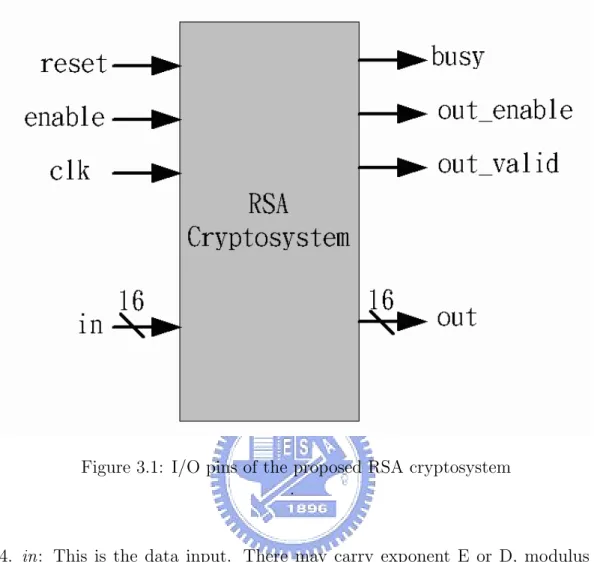
Figure. 3.1 show the input signals and output signals of the proposed architecture. The clk, reset, enable and in are input signals. The busy, out valid, out enable and
in are output signals. The data bandwidth of the proposed architecture is defined
as 16-bits and the total bandwidth of input signals and output signals is 38-bits. The I/O pins are described detail as following:
1. clk : This is the input pin of operation clock.
2. reset: This is in order to make initialization in the beginning of the cryptosys-tem work.
3. enable: This is the control signal to indicate that the data of the in signal is valid.
Figure 3.1: I/O pins of the proposed RSA cryptosystem .
4. in: This is the data input. There may carry exponent E or D, modulus N, pre-compute coefficient R2modN and operation mode type on the in signal.
5. busy: When the busy signal is high, it means the RSA cryptosystem is busy for another process.
6. out enable: When the out enable is high, it meets that the correct output data has been stored in the memory and ready for loading.
7. out valid: When the out valid is high, there is the correct result in the out signal.
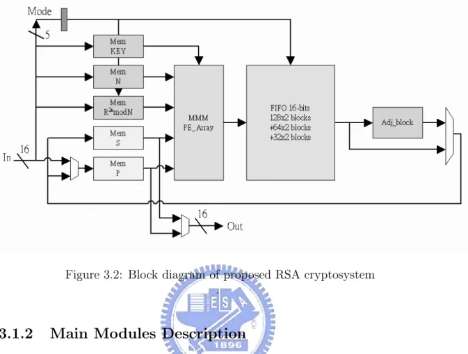
Figure 3.2: Block diagram of proposed RSA cryptosystem .
3.1.2
Main Modules Description
In order for the less bandwidth, the storage of data and the redundant cycles are needed. There are five memory block, processing element array, adjustment unit and 4096-bits FIFO, illustrated in figure. 3.2. The main modules are described detail as following:
1. Memory Block :
There are five memory block for using. The exponent E or D is stored in the ”key” memory. The modulus N is stored in the ”N” memory and the pre-compute coefficient 22nmodN is stored in the ”R2 mod N” memory. The
temporary values M2i
and Mj are stored in the ”S” and ”P” memories.
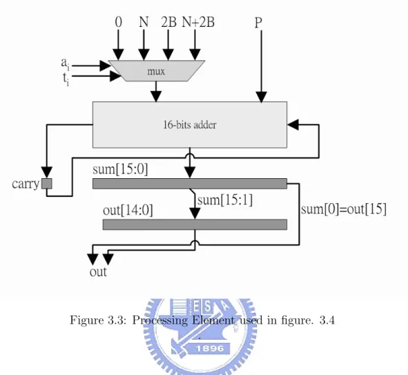
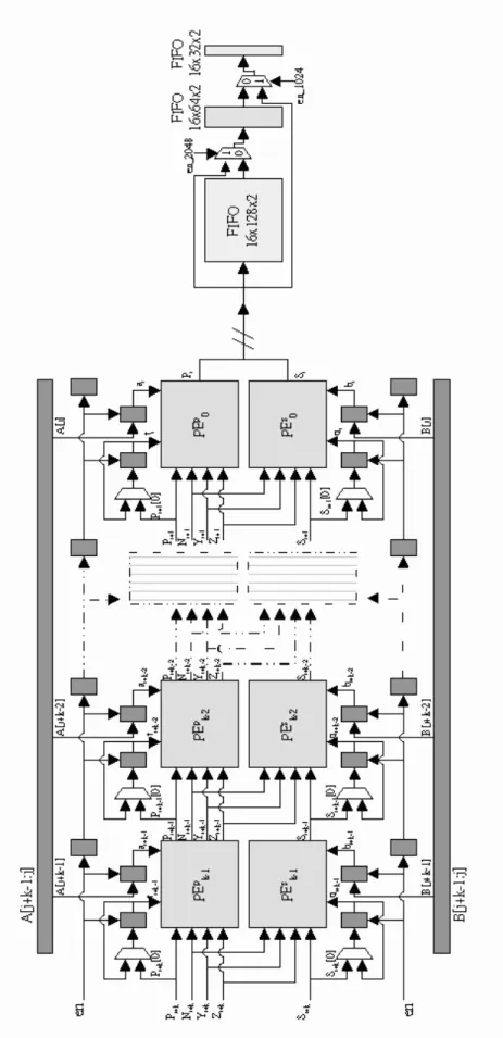
2. PE Array:
The processing element array is composed of 16 level processing elements. Each processing element has two-stage pipeline, as shown in the figure. 3.3.
Figure 3.3: Processing Element used in figure. 3.4 .
There are 16-bits ripple adder and 5 × 16-bits registers in each processing element. It takes 32 clock cycles to pass the PE array.
3. 224 ∗ 16-bits FIFO:
There are only 16-stages PE array. If the proposed RSA cryptosystem work with 4096-bits RSA encryption/decryption, it is not enough to store the tem-porary data. In order to make the proposed RSA cryptosystem work regular with 4096-bits RSA encryption/decryption, the registers are needed to store 4096 − 32 ∗ 16 = 224 ∗ 16 date.
4. Adjustment Adder :
In order to get the correct result, the output of the PE array would be subtracted by modulus N with adjustment adder in the finish of
tion/decryption. 5. Complete Detector :
It can compute the key length k of E or D and decide the iteration number of Montgomery modular exponentiation.
3.2
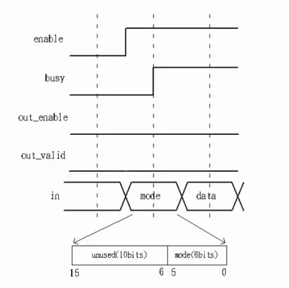
Operation Mode Description
When the enable signal turns from low to high, as shown in figure. 3.5, there is the message of the in signal with reference to mode type. Table. 3.1 indicates that there have three type of operation and four variety of block length. Three type of operation, which are encryption/decryption, configuration and result, depend on the in[5:4] signal. Encryption is the action to convert plaintext to ciphertext, and
decryption is the action to convert ciphertext to plaintext. Configuration is the
action to store the key into the memory. Result is the action to transmit the data of the memory to the out signal.
Figure 3.5: Load mode type .
When the out enable signal and out valid signal are both idle and the enable signal is high, it means that there have no useful plaintext or ciphertext in the memory and it can work at the Configuration or encryption/decryption mode.
Table 3.1: Mode Type
4096 bits 2048 bits 1024 bits 512 bits
(in[3:0]=4’b1000) (in[3:0]=4’b0100) (in[3:0]=4’b0010) (in[3:0]=4’b0001)
En/Decryption (in[5:4]=2’b00) (001000)2 (000100)2 (000010)2 (000001)2 Configuration (in[5:4]=2’b01) (011000)2 (010100)2 (010010)2 (010001)2 Result (in[5:4]=2’b10) (101000)2 (100100)2 (100010)2 (100001)2
Figure 3.6: Configuration completion .
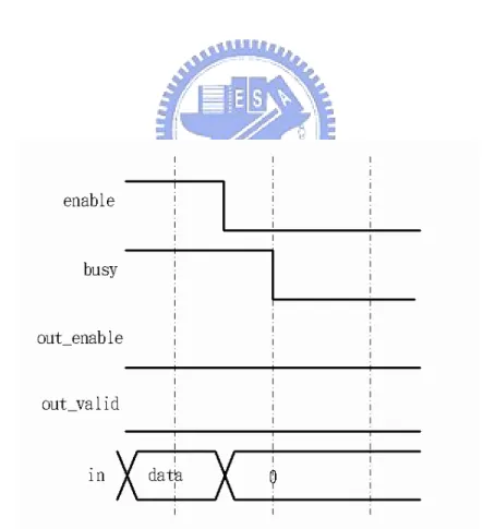
Figure 3.7: Correct output data stored .
Figure. 3.6 shows the state of configuration completion. When the operation mode type is Configuration, the busy signal turns from high to low after the enable signal turning from high to low. In this case, it is ready for the encryption/decryption mode. The busy signal is still high after the enable signal turning from high to low, if the RSA cryptosystem works at the encryption/decryption mode.
Figure. 3.7 shows that the out enable signal is asserted and the out valid signal is idle. That meets that the correct output data has been stored in the memory and ready for loading. The correct output data is ready for reading until the enable has been asserted. The Result mode indicates transmitting the correct output data form the memory block to the output signal, as shown in figure. 3.8. If the data of the output signal is correct, the out valid signal will be asserted. When the Result mode is complete, as shown in figure. 3.9, the busy, out valid and out enable signals will turn from high to low.
Figure 3.8: Read correct output data .
Figure 3.9: Encryption/Decryption finish .
Chapter 4
Implementation
4.1
Implementation with cell base design
The synthesized result is given bellow. The cycle time is set to 2.7ns and the synthesis standard library is UMC 0.18µm technology. The operation time for en-cryption/decryption depends on the efficient key length of E1024. For example, if
E1024=(0...010001)2=17, the efficient key length of E1024 is 5, and if E1024=(010...01)2
=21022+ 1, the efficient key length of E
1024 is 1023. Number of clock cycles for each
modular product is given by
n × (n + 4),
n is encryption/decryption block size.
The operation time for encryption/decryption is given by 2.7 × k × n
16 × (
n
16 + 4) (ns), k is the efficient key length of E or D.
The data throughput rate is given by 109× n
2.7 × k × n
16 × (16n + 4)
Table 4.1: The synthesized results with cell base design Design Cell base design Length (bits) (key and text) 512 1024 2048 4096
Technology UMC 0.18µm Clock frequency 370 MHz
Gate count 175.8k
Baud (kb/s) 314 83 21 5.4
For example, if n=512 and k=17, the data throughput rate is 109× 512
2.7 × 17 ×512
16 × (51216 + 4)
= 9.7 × 10⁶ (bit/sec)
= 9.23 (Mb/s). If n=512 and k=512, the data throughput rate is
109× 512
2.7 × 512 × 512
16 × (51216 + 4)
= 321.5 × 10³ (bit/sec) = 314 (kb/s).
The proposed RSA cryptosystem was implemented using Verilog. The logic synthesis is performed with Synopsys Design Aalyzer using UMC 0.18µm CMOS standard-cell technologies.
Table 4.2: The verification results on FPGA Design FPGA
Length (bits) (key and text) 512 1024 2048 4096 FPGA card iProve xc2v8000 Clock frequency 116.7 MHz Number of RAMB16s 5
Number of slices 6783 Total equivalent gate count 445,596
Baud (kb/s) 99 26 6.8 1.7
The clock frequency is set to 370MHz and the evaluate gate count is 175.8k. The detail value is shown as table. 4.1.
4.2
Implementation on FPGA
The verification is given by an integrated FPGA system. The proposed RSA cryp-tosystem was implemented onto the Xilinx Virtex2: XC2V8000. Table. 4.2 shows that the synthesis frequency is set to 116.7Mhz and the number of slices is 6783.
Chapter 5
Conclusion
An implementation of proposed reconfigurable RSA cryptosystem has been pre-sented in this paper. It is feasible to complete the 512, 1024, 2048 and 4096-bit RSA encryption/decryption with the proposed reconfigurable RSA cryptosystem on FPGA. This uses thirty-four 16-bit ripple adders, two 4096-bit FIFO and five 256*16-bit memory block. There are only 38 bits I/O that are 19 bits input and 19 bits output. The baud rate is 99kb/s for 512-bit, 29kb/s for 1024-bit, 6.8kb/s for 2048-bit and 1.7kb/s for 4096-bit RSA encryption/decryption. The number of slices is 6783.
Table. 5.1 shows the comparison with other 1024-bit RSA implementations with cell base design. The gate count without registers of the proposed architecture is smaller than [7], but the baud rate of the proposed architecture is higher than [7]. Table. 5.3 shows the comparison with other 1024-bit RSA implementations on FPGA. Fournaris [8] uses 1024-stages PE to implement the RSA cryptosystem. The word length of each PE is one bit. Nibouche [9] implements the multipliers of the RSA cryptosystem with the systolic array. McIvor’s [10] another approach uses CRT(Chinese Remainder Theorem) to speed up. Tang [11] implement the RSA cryptosystem with radix-217.
Table 5.1: Comparison with other 1024-bits implementations with cell base design
Authors Proposed Su [12] Cho [7] Mukaida [13]
Technology (µm) .18 .18 .18 .18
Methodology Reconfigurable Coprocessor not Montgomery CRT and radix232
Clock Frequency 370 83 40 200
(MHz) (synthesis result) (measurement result) (synthesis result) (synthesis result)
Total gate count 175.8k 120k 230k 965k
?Combinational gate count 37.1k 34k 156k 755k
?Register gate count 138.7k 86k 74k 210k
Baud Rate (kb/s) 83 67 78.8 5000
? is indicated that the value is estimated.
but it can work with 512/1024/2048/4096-bit RSA encryption/decryption. For the application of smart cards, it is a nice choice to reduce area.
Table 5.2: Comparison with other 512-bits implementations on FPGA
Authors Proposed Shao [14] Blum [15] McIvor [10] Tang [11]
Platform XC2V8000 XC2V XC2V4000 XC2V6000 XC2V3000
Methodology reconfigurable Booth N.A. CRT radix217
Clock Frequency (MHz) 116.7 100 95 116 99
Total number of slices 6783 N.A. 4440 13910 8235
?Number of slices (w/o registers) 1673 N.A. 1840 N.A. 5163
?Number of slices (registers) 5110 N.A. 2600 N.A. 3072
Baud Rate (kb/s) 99 355 86 887 1680
? is indicated that the value is estimated.
Table 5.3: Comparison with other 1024-bits implementations on FPGA
Authors Proposed Fournaris [8] Nibouche [9] McIvor [10] Tang [11]
Platform XC2V8000 N.A. XC2V8000 XC2V6000 XC2V3000
Methodology reconfigurable n-stage PE systolic CRT radix217
Clock Frequency (MHz) 116.7 129 78 97 90
Total number of slices 6783 7873 19900 26136 14334
?Number of slices (w/o registers) 1673 2241 N.A. N.A. 8190
?Number of slices (registers) 5110 5632 N.A. N.A. 6144
Baud Rate (kb/s) 26 119 148 376 429
Bibliography
[1] W. Stallings, Cryptography and Network Security: Principles and Practice. Prentice Hall, 2002.
[2] R. L. Rivest, A. Shamir, and L. M. Adelman, “A method for obtaining digital signatures and public key cryptosystems,” Communication of the ACM, vol. 21, no. 2, pp. 120–126, 1978.
[3] K. Koc, “High-speed rsa implementation,” tech. rep., RSA Laboratories, 1994. [4] P. L. Montgomery, “Modular multiplication without trial division,”
Mathemat-ics of Computation, vol. 44, no. 170, pp. 519–521, 1985.
[5] C. C. Yang, T. S. Chang, and C. W. Jen, “A new rsa cryptosystem hardware design based on montgomerys algorithm,” in IEEE Trans. on Circuits and
Systems - II: Analog and Digital Signal Processing, vol. 45, pp. 908–913, July
1998.
[6] C. H. Wang, C. P. Su, C. T. Huang, and C. W. Wu, “A word-based rsa crypto-processor with enhanced pipeline performance,” pp. 218–221, Aug 2004. [7] K. S. Cho, J. H. Ryu, and J. D. Cho, “High-speed modular multiplication
algorithm for rsa cryptosystem,” IEEE Industrial Electronics Society (IECON), vol. 1, no. 6, pp. 479–483, 2001.
[8] A. P. Fournaris and O. Koufopavlou, “A new rsa encryption architecture and hardware implementation based on optimized montgomery multiplication,” in
proceedings of 2005 IEEE International Symposium on Circuits and Systems (ISCAS 2005), vol. 5, pp. 4645–4648, May 2005.
[9] O. Nibouche, M. Nibouche, A. Bouridane, and A. Belatreche, “Fast architec-tures for fpga-based implementation of rsa encryption algorithm,” in
Proceed-ings of the 2003 IEEE International Conference on Field Programmable Tech-nology (FPT), pp. 271–278, Dec 2004.
[10] C. McIvor, M. McLoone, and J. V. McCanny, “Modified montgomery modular multiplication and rsa exponentiation techniques,” in IEE Proceedings
Com-puters and Digital Techniques, vol. 151, pp. 402–408, Nov 2004.
[11] S. H. Tang, K. S. Tsui, and P. H. W. Leong, “Modular exponentiation using parallel multipliers,” in Proceedings of the 2003 IEEE International Conference
on Field Programmable Technology (FPT), pp. 52–59, Dec 2003.
[12] C. P. Su, C. H. Wang, K. L. Cheng, C. T. Huang, and C. W. Wu, “Design and test of a scalable security processor,” in Proc. Asia and South Pacific Design
Automation Conf. (ASP-DAC), vol. 1, pp. 372–375, Jan 2005.
[13] K. Mukaida, M. Takenaka, N. Torii, and S. Masui, “Design of high-speed and area-efficient montgomery modular multiplier for rsa algorithm,” IEEE Symp.
VLSI Circuits, pp. 320–323, Jun 2004.
[14] J. Shao and S. Kort, “A high speed 512-bit modular multiplier for a rsa chip,”
IEEE international Northeast Workshop on Circuits and Systems (NEWCAS),
pp. 237–240, Jun 2004.
[15] T. Blum and C. Paar, “Montgomery modular exponentiation on reconfigurable hardware,” in Proc. 14th IEEE Symposium on Computer Arithmetic