Fabrication of High-Aspect-Ratio Ceramic
Microstructures by Injection Molding with the
Altered Lost Mold Technique
Ren-Haw Chen and Chih-Lung Lan
Abstract—A fabrication process for complex ceramic mi-crostructures was proposed that combines a lost mold technique and ceramic injection molding. Two key points in this process were studied. First, the solubility of several engineering plastics in various organic solvents was tested to find appropriate combina-tions of mold material and solvent for dissolving molds. Secondly, the binder extraction rate and the strength of a green body during debinding were investigated. Experimental results indicate that acrylonitrile-butadiene styrene and acetone are the best combi-nations selected for this lost mold technique. We also propose that using gasoline as the debinding solvent and performing the debinding at room temperature will give a good time-saving effect and avoid toppling the microstructure if paraffin wax, stearic acid, and polyethylene were selected to compound the binder system. This process has been successfully applied to fabricate several ceramic microstructures, such as integrated punch. [575]
Index Terms—Ceramic injection molding, ceramic microstruc-ture, extraction rate, lost mold technique, solubility, toppling.
I. INTRODUCTION
T
HE development of ceramic microsystems is greatly in-fluenced by whether an appropriate structuring technique is available. Several structuring techniques have been recently applied to ceramic microstructures with simple configurations [1], [2]. For more desired ceramic microstructures with com-plex shapes or a high aspect ratio, injection molding is widely utilized [3]–[5]. However, a normal ceramic injection-molding process [6], [7] has difficulty keeping the green body of the mi-crostructure free from fracturing when demolded. To avoid this problem, introducing the concept of “lost mold” into the ceramic injection molding process is a worthwhile task.Various lost mold techniques have been applied to ceramic microstructuring [8]–[13]. The conventional approach uses a plastic sacrificial mold and burns it out following molding [8]–[10]. However, during firing, the molten plastic material of the mold flows due to gravitation and gaseous bubbles form in the melt owing to plastic depolymerization and oxidation. Consequently, drag force acted by the viscous fluid increases the load on the softened green body, and surface tension of gas bubbles affects the microstructure locally; furthermore, viscous molten plastic constrains the gasified organic binder
Manuscript received May 9, 2000; revised September 21, 2000. Subject Ed-itor, C-J. Kim.
The authors are with the Department of Mechanical Engineering, National Chiao Tung University, Hsinchu, 30010 Taiwan, R.O.C.
Publisher Item Identifier S 1057-7157(01)01592-X.
from escaping. Therefore, when the mold is burning out, the microstructure might suffer from deformation, toppling, or cracking, which restricts the manufacture of high-aspect-ratio ceramic microstructures. Some researchers have attempted to replace mold-burning with plasma etching to avoid the trouble caused by heating [11]. However, this approach increases process requirements such as masking and cannot ensure that the green microstructure is free from lateral erosion. Another lost mold technique was recently developed for fabricating PZT microstructure [12]. That process utilized a silicon mold and performed PZT sintering without removing the mold. The silicon sacrificial mold was then removed by dry etching following the PZT sintering. Such a case of a silicon mold is only appropriate for ceramic materials with a relatively low sintering temperature.
Herein, a lost mold technique is developed and integrated into ceramic injection molding for the structuring of high-as-pect-ratio microstructures of most ceramics. This process uses a plastic mold as the sacrificial mold and to completely remove this sacrificial mold via solvent dissolving, without damaging the microstructure is the key point. Appropriate combinations of plastic mold material and organic solvent are suggested. Mean-while, the essentials of a binder system for this process are also discussed. Subsequently, debinding conditions concerning the process efficiency and strength of the microstructure during de-binding are developed. Finally, some application examples are introduced.
II. THELOSTMOLDTECHNIQUECOMBINEDCERAMIC
INJECTIONMOLDINGPROCESS
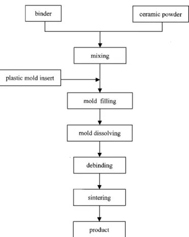
Fabrication of microstructure components from ceramic ma-terials by the injection-molding process, including a lost mold procedure of solvent dissolution, comprises several steps.
1) Manufacturing a complementary plastic structure by means of micromachining or micromolding. This plastic mold then is placed in a steel mold base.
2) Preparing the mixture of organic binder and ceramic powder. The binder and powder are carefully mixed to an appropriate volume fraction.
3) Heating the mixture and then injecting it into the mold cavity.
4) Removing the ceramic green part and plastic mold that adhere to each other from the mold base and immersing them in an appropriate solvent to dissolve the plastic sac-rificial mold and obtain the free green microstructure.
TABLE I
PROPERTIES OFSEVERALENGINEERINGPLASTICS
Fig. 1. Major steps of the ceramic injection-molding process combined with the lost mold technique of solvent dissolving.
5) Removing the organic binder from the microstructure. Solvent extraction [14], [15] or thermal debinding [16], [17] can be used.
6) Sintering the parts to eliminate most of the resulting porosity from the debinding cycle, achieving a high theoretical density percentage [18].
Fig. 1 is a flowchart of this process.
III. LOSTMOLDTECHNOLOGY BYDISSOLUTION
To ensure the quality of the solvent dissolving process of the plastic mold, the selected combination of the kind of plastic ma-terial and organic solvent is very important. The plastic mama-terial used must have a good mechanical processability or moldability for convenient manufacturing of the mold of the microstructure.
Meanwhile, properties of sufficient strength, wear resistance, and high thermal deformation temperature are also essential to prevent the mold from deformation or excessive wear due to heat and stresses brought by the flow of the molding mixture during mold filling and packing. However, extreme solubility of the plastic mold is the key requirement. Restated, a suitable sol-vent must be found to completely dissolve the selecting plastic. Moreover, this solvent must not be harmful to the green mi-crostructure.
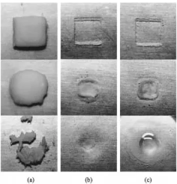
Table I lists the properties of several engineering plastics that can be utilized as the mold material. Solubility properties in or-ganic solvents of these materials are determined by intermolec-ular forces that exist between each material and the solvent being matched with it. In general, polar materials dissolve in polar solvents and nonpolar materials dissolve in nonpolar sol-vents. This study uses acetone, toluene, chloroform, and gaso-line to test the solubility of the plastic materials listed in Table I. Fig. 2 presents some of the testing results that have the best so-lution effects. Solid acrylonitrile-butadiene styrene (ABS) be-come cloud-like matter suspended in the liquid acetone after a period of immersion, and this matter can easily be dispersed into the acetone as a semitransparent solution by slight shaking, as shown in Fig. 2(a). This behavior means that extreme sol-ubility can be achieved while ABS is matched with acetone. Competitively excellent results can also be expected from the example of polycarbonate (PC) with chloroform, as shown in Fig. 2(b). Obviously, these two combinations of plastic mate-rial and organic solvent meet the basic requirements of the lost mold process being developed here. As for the case of poly-methylmethacrylate (PMMA) being immersed in chloroform, as shown in Fig. 2(c), solid PMMA softens and becomes thick and viscous in the liquid but does not dissolve well. This be-havior leads to the combination of PMMA and chloroform, not satisfying the requirements of the lost mold method because it is difficult to remove softened viscous mold material from the periphery of the microstructure. Meanwhile, the other combina-tions not shown in Fig. 2 are not suitable for use with the lost mold method due to their low solubility. In these combinations, the solubility is so low that it can barely be measured or even observed.
Explaining why solubility differs between each combination of plastic material and organic solvent is difficult. In fact, solubility of organic compounds is very sensitive to the effect of intermolecular forces. Three major attractive forces that
Fig. 2. Comparison of solubility of (a) ABS in acetone, (b) PC in chloroform, and (c) PMMA in chloroform. The experiment was performed at 20 C and photographed when specimens had been immersed for 1, 3, and 6 h from up to down, respectively. All specimens initially had the same dimensions, 10 mm along both edges and 2 mm thick.
Fig. 3. Molecular structure of (a) ABS, (b) acetone, (3) PC, and (d) chloroform.
cause molecules to associate into solids and liquids exist: the dipole–dipole forces of polar molecules, the van der Waals forces that affect all molecules, and the “hydrogen bonds” that link molecules having OH or NH groups [19]. Fig. 3 illustrates the molecule structures of acetone, ABS, chloroform, and PC. Since the molecular dipole moment is a good indicator of the
overall polarity of a molecule, herein it is measured experimen-tally [19] to have a high value of 2.9 D (debye) and 1.0 D for acetone and chloroform, respectively. Meanwhile, the existence of the strongly polar C N: triple bond, as shown in Fig. 3(a), indicates that strong polarity should appear on acrylonitrile in ABS copolymer. Consequently, ABS dissolve easily in acetone. As for the combination of PC and chloroform, the molecular dipole moment of chloroform is weaker than that of acetone. Nevertheless, since PC has many ester groups, OC O, that form hydrogen bonds with the chloroform molecules, the sol-ubility of PC in chloroform is significantly increased. Herein, ABS and acetone are selected for the use of lost mold purpose for further work in considering environmental protection and health care.
IV. THEBINDERSYSTEM
The binder system combined with the ceramic powder is important in ceramic injection-molding process. Generally, the binder system is composed of various organic additives. Considerations for selecting the binder system include the fluidity and formability of molding material during filling, the deformation resistance of the microstructure during handling and debinding, and finally the debinding property. The erosion resistance of the green microstructure during sacrificial mold’s being dissolved and the strength of the high-aspect-ratio microstructure during debinding deserve particular attention in the process developed herein.
Numerous compositions of binder system can be selected for a certain type of ceramic powder, provided they focus on the fluidity and formability of the mixture. However, more limita-tions emerge when considering the erosion resistance of green microstructure during mold dissolution and the debinding re-quirements that satisfy a high-aspect-ratio microstructure.
The strength consideration of a high-aspect-ratio microstruc-ture during the debinding stage governs the selection of de-binding method. In thermal dede-binding, since all the compo-sitions of a binder system are softened owing to heating, the yield strength and deformation resistance of the ceramic mix-ture will reduce, allowing the mixmix-ture to creep easily. More-over, some of the liquid binder seeping out through the surface will cause the siphon phenomenon at the gap between any two extremely close outstanding parts of the structure. Therefore, one type of toppling defect may occur due to surface tension of the seeped liquid binder. Furthermore, thermal debinding will cause negative influences owing to thermal stresses. For these reasons, thermal debinding is unfavorable to high-aspect-ratio microstructures. On the other hand, the solvent extraction de-binding process has little or no thermal stress problem. This process can be designed to selectively remove the various ingre-dients of the binder system so as to control the debinding ratio and obtain sufficiently strong debinded parts. Consequently, the solvent extraction debinding method is utilized for the ceramic injection-molding process developed herein.
According to the requirements described above, some criteria for choosing the binder system can be induced.
1) The binder system must not dissolve in the solvents se-lected for mold removing.
TABLE II
COMPOSITIONS OFEXPERIMENTMATERIALS(vol. %)
TABLE III
PROPERTIES OFSELECTEDSOLVENTS FORDEBINDING
2) The major ingredients of the binder system should dis-solve easily in debinding dis-solvents.
3) An appropriate proportion of minor ingredients, which does not dissolve in the debinding solvents, is added so as to keep the microstructure sufficiently strong after de-binding.
4) The binder system should have a low melting tempera-ture and low viscosity for the convenience of low-pres-sure molding at a comparatively low temperature. 5) A little lubricant must be added to improve the fluidity of
the mixture.
Table II shows the compositions of ceramic mixtures used herein. Paraffin wax is the major ingredient of the binder system, and polyethylene (PE) is the minor ingredient. Mean-while, stearic acid acts as the lubricant. Both paraffin and PE are polymers of relatively low molecular weight. Neither dissolves in acetone, which is used as the solvent for mold removal herein. Regarding the expected marked difference of the debinding property of paraffin and PE, it still depends on the selection of debinding solvent.
V. ESSENTIALS OFDEBINDINGMICROSTRUCTURES WITHHIGH
ASPECTRATIO
Once mold filling is completed and the sacrificial mold has been removed, debinding should be performed. Hexane, gaso-line, decalin, and tetralin, respectively, are used as the solvents for comparing the debinding property. These four solvents all are confirmed to have a good extraction ability for paraffin but do not easily dissolve the PE. Thus they all meet the second and third criteria described in the previous section. Table III lists some of their properties. Meanwhile, Fig. 4 shows the debinding
Fig. 4. Extraction rate of paraffin wax and stearic acid in ceramic green parts extracted by various organic solvents at 20 C.
Fig. 5. Extraction rate of paraffin wax and stearic acid in ceramic green parts extracted by various organic solvents. Cases of decalin and tetralin are at elevated temperature.
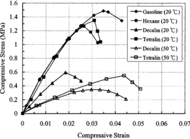
Fig. 6. Stress-strain curves for debinding material in compression. The maximum compressive strain rate is 0.003 s .
effects of these solvents on the experiment material code C (see Table II). The figure illustrates that the order of extraction rate
Fig. 7. (a), (b) Optical photograph and (c) scanning electron micrograph of the molded ceramic microstructure sample (integrated punch).
to the binder distributed in the material at room temperature is gasoline hexane decalin tetralin. Notably, however, the flashing points of decalin and tetralin are significantly higher than those of gasoline and hexane, as shown in Table III. This difference means that debinding may be performed at an ele-vated temperature to improve the extraction rate of the binder when decalin or tetralin is used as the solvent. Fig. 5 shows that at the elevated temperature of 50 C, the extraction rate of the binder by decalin and tetralin, respectively, are greatly increased and surpass the performance of gasoline at 20 C. The effect of temperature on binder extracting ability in this material case is clearest when tetralin is utilized.
However, for ceramic microstructures with a high aspect ratio, two more important facts during debinding process should be considered. One is the strength of material to avoid the occurrence of fracture. The other is the deformation resistance to reduce the structural deformation. Fig. 6 presents the compressive test results of materials’ being debinded from experiment material code C under various debinding conditions. The compressions are performed while material is in a situation where the extraction ratio of wax and stearic acid is 98 99 wt.%. The results in Fig. 6 and observations during testing reveal that generally, serious slipping occurs abruptly as the stress increases to a critical value, and then deforma-tion resistance rapidly decreases. The case where material is debinded by gasoline at 20 C has the best fracture strength and deformation resistance. Meanwhile, higher debinding
Fig. 9. Effect of solid loading on the density of the ceramic/binder mixture.
Fig. 10. Scanning electron micrograph of the ceramic microcolumn array.
the strength of the debinding body. Thus, gasoline may be the best selection of solvent for debinding the material used in this work, judging by the extraction efficiency of the binder and the quality of the debinded microstructure.
VI. APPLICATIONEXAMPLES
The novel process has been successfully applied to the struc-turing of several ceramic microstructures where ABS mold in-serts were used, and acetone and gasoline were utilized as the solvents for mold dissolution and debinding, respectively. Fig. 7 displays an integrated punch for making IC leadframe. The ob-jective of the design is to make a leadframe with a high pin count in just one punching cycle, thus decreasing the production cost and reducing the lead warping problem. The height of the punch edge is 500 m, and its thinnest dimension is slightly less than 100 m. The injection molding condition used is as follows: mold temperature 80 C, barrel temperature 150 C, and injec-tion pressure 30 MPa. Fig. 8 shows that cracks can be found near the connection between an edge and the center of a punch if an experimental material with lower solid loading (code A) was used. However, cracks never recurred when the solid loading of the material used was increased to 61 vol.%. To explain the dif-ference in crack occurring caused by the change of solid loading
of material, herein, the relationship between the density and the solid loading of the ceramic/binder mixture should be consid-ered. As Fig. 9 shows, the maximum density of the mixture used in this work can be obtained when the solid loading is 63 vol.%. Generally, this critical loading varies with the mean par-ticle size and parpar-ticle shape and voids may form in the mixture when solid loading exceeds this value. Accordingly, much more excess binder exists between ceramic particle and particle in the material of code A can be expected. This material characteristic of code A will result in large shrinkage in the molded green parts because the volume reduction of the excess binder due to cooling directly causes the shrinking of ceramic green parts, and the magnitude of shrinkage is proportional to the amount of ex-cess binder. Therefore, cracking will occur in the green parts whose dimensional change is restricted by the mold. Fig. 10 dis-plays another application example. A column array with pitch 800 m, column diameter 400 m, and column aspect ratio 5 was structured with a base plate. The surface pattern of mold insert was clearly imprinted onto the wall of columns.
VII. CONCLUSION
A lost mold technique-combined ceramic injection-molding process for complex and high-aspect-ratio ceramic microstruc-tures was presented herein. The lost mold technique, which uti-lizes organic solvent to dissolve a plastic mold, has been demon-strated to obtain excellent demolding results without damage, making it very suitable for microstructure fabrication. ABS and acetone appear to be an ideal combination of mold material and solvent for this lost mold process. As for the design of the binder system for this developed process, the erosion resistance of the green body during the mold dissolving cycle must be included in the consideration. Additionally, increasing the deformation resistance and material strength in the debinding process are key issues for raising the achievable aspect ratio of ceramic mi-crostructures. The ideal selection of debinding solvent depends on the composition of the binder. In this research, with a binder system that consisted of paraffin wax, stearic acid, and PE, gaso-line was utilized as the debinding solvent.
ACKNOWLEDGMENT
The authors would like to thank R.-S. Yang and Dr. M.-C. Chou of Mechanical Industry Research Laboratories, ITRI, Taiwan, R.O.C., for their many helpful discussions and contin-uous support.
REFERENCES
[1] R. Knitter, E. Günther, U. Maciejewski, and C. Odemer, “Herstellung keramischer Mikrostrukturen,” in Ber. DGK 71, 1994, pp. 549–556. [2] H. Freimuth and M. Stadel, “Ceramic microstructures,” in UETP Series
on Micro Electro Mechanical Systems, H. Möbius, Ed: Neuchatel, 1995,
pp. 42–51.
[3] L. Weber, W. Ehrfeld, H. Freimuth, M. Lacher, H. Lehr, and B. Pech, “Micro molding—A powerful tool for the large scale production of pre-cise microstructures,” in Proc. SPIE, vol. 2879, Oct. 1996, pp. 156–167. [4] J. Inahashi, “Fabrication of micro-machine parts by MIM” (in in
Japanese), Plastic Process. Technol., vol. 12, no. 4, pp. 57–60, 1995. [5] L. J. Bowen and K. W. French, “Fabrication of piezoelectric
ce-ramic/polymer composites by injection molding,” Proc. IEEE 8th Int.
[6] K. Schwartzwalder, “Injection molding of ceramic materials,” Amer.
Ceram. Soc. Bull., vol. 28, no. 11, pp. 459–461, 1949.
[7] M. A. Strivens, “Injection molding of ceramic insulating materials,”
Ceram. Bull., vol. 42, no. 1, pp. 13–19, 1963.
[8] K. Lubitz, A. Wolff, and G. Preu, “New piezoelectric composites for ultrasonic transducers,” Ferroelectrics, vol. 133, pp. 21–26, 1992. [9] W. A. Smith, “New developments in ultrasonic transducers and
trans-ducer systems,” in Proc. SPIE, vol. 1733, 1992, pp. 113–116. [10] A. Bandyopadhyay, R. K. Panda, V. F. Janas, M. K. Agarwala, S. C.
Danforth, and A. Safari, “Processing of piezocomposites by fused depo-sition technique,” J. Amer. Ceram. Soc., vol. 80, no. 6, pp. 1366–1372, 1997.
[11] Y. Hirata, H. Okuyama, S. Ogino, T. Numazawa, and H. Takada, “Piezoelectric composites for micro-ultrasonic transducers realized with deep-etch x-ray lithography,” in Proc. IEEE MEMS Conf., 1995, pp. 191–196.
[12] S. N. Wang, J.-F. Li, R. Toda, R. Watanabe, K. Minami, and M. Esashi, “Novel processing of high aspect ratio 1-3 structures of high density PZT,” in Proc. IEEE MEMS Conf., 1998, pp. 223–228.
[13] A. Safari, V. Janas, and R. Panda, “Fabrication of fine-scale 1.3 Pb(Zr , Ti )O ceramic/polymer composites using a modified lost mold method,” in Proc. SPIE, vol. 2721, 1996, pp. 251–262.
[14] S. T. Lin and R. M. German, “Extraction debinding of injection molded parts by condensed solvent,” Powder Met. Int., vol. 21, pp. 19–24, 1989. [15] “Sumitomo Heavy Industries, Ltd.,” (in Japanese), , Tech. Rep. , vol. 36,
1988.
[16] B. C. Mutsuddy, “A review of binder removal processes for ceramic injection moulded parts,” in Proc. AIChE Conf. Emerging Technology
in Materials, Aug. 1987, pp. 18–20.
[17] R. M. German, “Theory of thermal debinding,” Int. J. Powder Met., vol. 23, pp. 237–245, 1987.
[18] F. Thummler and W. Thomma, “The sintering process,” Metallurgical
Rev., vol. 12, pp. 69–108, 1967.
[19] L. G. Wade, Organic Chemistry. Englewood Cliffs, NJ: Prentice-Hall, 1987, pp. 56–59.
Ren-Haw Chen received the B.S. degree from
Feng Chia University, Taiwan, R.O.C., in 1984 and the M.Eng. and Dr.Eng. degrees from the Tokyo Institute of Technology, Japan, in 1991 and 1994, respectively, all in mechanical engineering.
From 1994 to 1996, he joined the Industrial Technology Research Institute, Hsinchu, Taiwan, developing molding techniques for optical devices and ceramic microstructures. Since 1996, he has been an Associate Professor at the Mechanical Engineering Department, National Chiao Tung University, Hsinchu. His main interest is the rheological behavior of material in microprocessing.
Chih-Lung Lan received the B.S. degree from National Chung Hsing
Univer-sity, Taiwan, R.O.C., in 1997 and the M.S. degree from National Chiao Tung University, Taiwan, in 1999, both in mechanical engineering.
At National Chiao Tung University, he worked on the micromolding of ce-ramic microstructures. He currently is a Reserve Officer in the army of the Re-public of China.