Electrophoretic deposition of PtRu nanoparticles on carbon nanotubes for
methanol oxidation
Yu-Kuei Hsu
a, Ju-Lan Yang
b, Yan-Gu Lin
b, San-Yuan Chen
b, Li-Chyong Chen
c, Kuei-Hsien Chen
a,c,⁎
a
Institute of Atomic and Molecular Science, Academia Sinica, Taipei 106, Taiwan
bDepartment of Materials Science and Engineering, National Chiao Tung University, Hsinchu 300, Taiwan c
Center for Condensed Matter Sciences, National Taiwan University, Taipei 106, Taiwan
a b s t r a c t
a r t i c l e i n f o
Available online 5 November 2008 Keywords:
Carbon nanotubes PtRu
Electrophoretic deposition Methanol oxidation
Electrophoretic deposition technique was successfully utilized to deposit the PtRu nanoparticles on carbon nanotubes, which were directly grown on carbon cloths (CNTs/CC). We applied an external dcfield to drive the PtRu nanoparticles, which were surrounded by negatively charged glycolate in an ethylene glycol process, toward the positively biased CNTs. Systematic studies to achieve optimal size and loading amount by varying the bias potential and deposition time have been carried out. An average PtRu particle size of 2.08 nm with catalytic activity of 1.6 A/cm2/mg in electro-oxidation methanol could be achieved, which is highly desirable for fuel cell applications.
© 2008 Published by Elsevier B.V.
1. Introduction
Nano-sized PtRu electrocatalysts are regarded as the most effective anode catalysts for direct methanol fuel cells (DMFC)[1–3]. Highly dispersed PtRu nanoparticles (NPs) onto nanostructured carbon materials, especially one-dimensional carbon nanotubes (CNTs), are efficient pathway for methanol oxidation due to superior electronic conductivity, anti-corrosion ability, and high surface area of CNTs[4–8]. However, the existing route to mix the CNTs, PtRu NPs, and Nafion solution to produce membrane electrode assembly (MEA) is not effective due to the energy losses associated with internal resistance and contact resistance in the system. In order to ensure the optimum conditions for electron transfer through CNTs, several works have been focused on the systems based on PtRu electrocatalysts supported by CNTs directly grown on carbon cloths (PtRu/CNTs/CC), which could provide an efficient electron path to reduce the interfacial energy loss[9–13]. Recent study by Wang et al. introduced the PtRu/ CNTs/CC membrane electrodes as the most attractive route to develop direct methanol fuel cells (DMFC) with high efficiency[10].
Up to now, the most common methods used to prepare hybrid electrocatalysts include impregnation–reduction[14–16]and colloidal
[17–19] approaches, which are attractive for large-scale synthesis. However, in order to efficiently deposit nanosized PtRu alloy onto CNTs surface with uniform dispersion, it is necessary to activate the
graphitic surface of the nanotubes that tend to be chemically inert. Most of activated treatments of CNTs surface need to be functionalized by harsh oxidative processes, such as refluxing in H2SO4 or HNO3 solution, to create carboxylic (–COOH), carbonyl (–C=O), and hydroxyl (–OH) groups, providing chemical links to NPs[20]. Unfortunately, these strong acid treatments not only reduce the mechanical and electronic performance of nanotubes due to the introduction of large numbers of defects, but also peel the CNTs off from CC. Recently, the electrochemical deposition method[13]and sputtering method[10]
were attempted to deposit the PtRu NPs onto CNTs/CC electrodes. But, those methods still have problems in the irregular size distribution and the limitation of shrinking size of PtRu NPs. Hence, the varied technique for the preparation of these hybrid membrane electrodes is urgent demand.
Herein, an attractive alternative route to synthesis of PtRu/CNTs/CC membrane electrodes is proposed by means of electrophoretic deposition (EPD), which is a colloidal processing method where the charged particles dispersed in a liquid medium are attracted and deposited onto a conductive and oppositely biased electrode. It has the advantages of fast, simple, and size controllability[21]. Essentially, the CNTs/CC electrodes have excellent electric conductivity that can easily fulfill the requirement of EPD without any surface pretreatment process. Furthermore, an effective method for synthesis of PtRu colloids in ethylene glycol (EG) without adding traditional protective agents has been reported[17], in which the colloids are stabilized by glycolate coming from EG oxidation and the size of PtRu colloids are within the range of 0.7–4 nm, which is controlled via the pH of the synthesis solution. Since these suspended PtRu alloy NPs are surrounded by the anionic glycolate, the positively charged CNTs/CC ⁎ Corresponding author. Institute of Atomic and Molecular Science, Academia Sinica,
Taipei 106, Taiwan.
E-mail address:[email protected](K.-H. Chen). 0925-9635/$– see front matter © 2008 Published by Elsevier B.V. doi:10.1016/j.diamond.2008.10.045
Contents lists available atScienceDirect
Diamond & Related Materials
electrode, under a dc bias, is able to electrostatically adsorb and deposit the negatively charged NPs onto the electrode surface. By means of the deposition (EPD) time, the loading of PtRu NPs can be controlled without altering the size and shape of NPs. Hence, this approach, combining EPD with EG-colloidal process, not only well-defines the size of PtRu nanocatalysts, but also facilitates the loading control of catalysts.
2. Experimental section 2.1. CNTs growth on CC growth
The CNTs/CC hybrid membrane electrodes were prepared by iron-catalyst assisted microwave plasma-enhanced thermal vapour deposi-tion MPECVD technique. First, iron was sputtered onto CC using ion beam sputtering deposition system (Commonwealth Scientific. Co. Ltd.). The CC was positioned in parallel to the iron target (99.95%) and was kept 20 cm from the target; while an ion beam, from a Kaufman type ion source, was incident onto the target at an angle of 40°. Before the deposition, the chamber was evacuated using a turbo molecular pump to a base pressure of 5 × 10⁻⁶Torr and then a working pressure was kept at 5 × 10⁻⁴Torr under argon atmosphere during deposition. The Kaufman ion source was operated with a beam voltage and current of 1250 V and 20 mA, respectively. The optimised deposition time of iron catalyst was 10 min. Prior to the growth of CNTs, the iron-coated CC was subjected to hydrogen-plasma treatment of the catalyst at microwave power of 1 kW, under chamber pressure 28 Torr for 10 min. At this step, catalyst layer was transformed into nanoparticles. It should be emphasized that, in fact, the hydrogen plasma treatment of catalyst layer was critical to the growth and the size of CNTs, because the treatment not only cleaned and reduced the surface of the catalyst but also produced more active catalyst sites. Subsequently, the synthesis of CNTs was carried out in a mixture of precursors (CH4/H2/N2= 20:80:80), at microwave power of 2 kW, under chamber pressure 40 Torr, substrate temperature 900 °C for growth time 10 min.
2.2. Preparation of PtRu/CNTs/CC
The synthesis of the bimetallic PtRu colloid was carried out in EG solution as solvent and reducing agent, in which the platinum chloride (PtCl4) and ruthenium chloride (RuCl3) were the precursors. Typically, 3 mL of PtCl4(33.7 mg mL− 1) and 5.5 mL of RuCl3(11.3 mg mL− 1) were mixed in 30 mL of EG solution with pH adjusted to 11.2 using sodium
hydroxide (0.5 M NaOH in EG). The solutions were stirred for 30 min in air at room temperature, subsequently refluxed at 140 °C for 2 h to ensure complete reaction, and then cooled in air. Dark brown solut-ions containing the suspended PtRu colloids were formed and referred as the colloidal solution in this work.
Following the synthesis of the colloidal solution, EPD was carried out to deposit the bimetallic PtRu NPs onto CNTs/CC electrode surface. The deposition setup consisted of CNTs/CC and Pt sheet as two parallel electrodes, which were immersed into colloidal solution and kept at a distance of 5 mm between two. A conventional dc power supply was used to generate an applied voltage of 0.1, 0.5, 1, 2, 5 V for deposition time of 10, 20, 40, 60, 80, and 100 min. Finally, the PtRu/CNTs/CC were thoroughly rinsed with distilled water and dried at 160 °C for 1 h. 2.3. Characterizations
Both field-emission transmission electron microscopy (FETEM, JEM-4000EX) and high-resolution scanning electron microscopy (HRSEM, JEOL-6700) were used to study the microstructure evolution of the CNTs/CC composite electrode. The atomic ratio and mass per unit area of the metals were determined by electron spectroscopy for chemical analysis (ESCA, Perkin-Elmer model PHI 1600) and induc-tively coupled plasma-optical emission spectroscopy (ICP-OES, Per-kin-Elmer ICP-OES Optima 3000). Electrochemical measurements were conducted using Solartron electrochemical test system (1470E) at room temperature. The counter and the reference electrodes were Pt sheet and Ag/AgCl, respectively. All potentials reported in this article were with respect to Ag/AgCl (3 M KCl, 0.207 V vs. SHE). Samples were put into a specific holder as the working electrode, which was connected to test system with a gold wire. Prior to the measurements, the samples were cleaned thoroughly by DI water to remove the possible impurities. All solutions were degassed using high purity nitrogen and the cyclic voltammetry (CV) results were collected after the corresponding CV scans reached a steady state. 3. Results and discussion
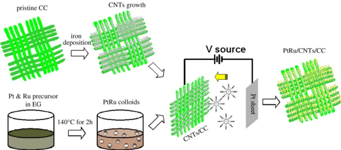
The procedure of preparation for hybrid PtRu/CNTs/CC electrodes, which combined EPD method with EG process, was illustrated schematically inFig. 1. Highly dense CNTs of around 20–30 nm in diameter and 3–5 µm in length were directly grown on the carbon fibers (CC) by MPECVD system. Meanwhile, the uniform size of PtRu colloidal solution was synthesized based on EG technique with
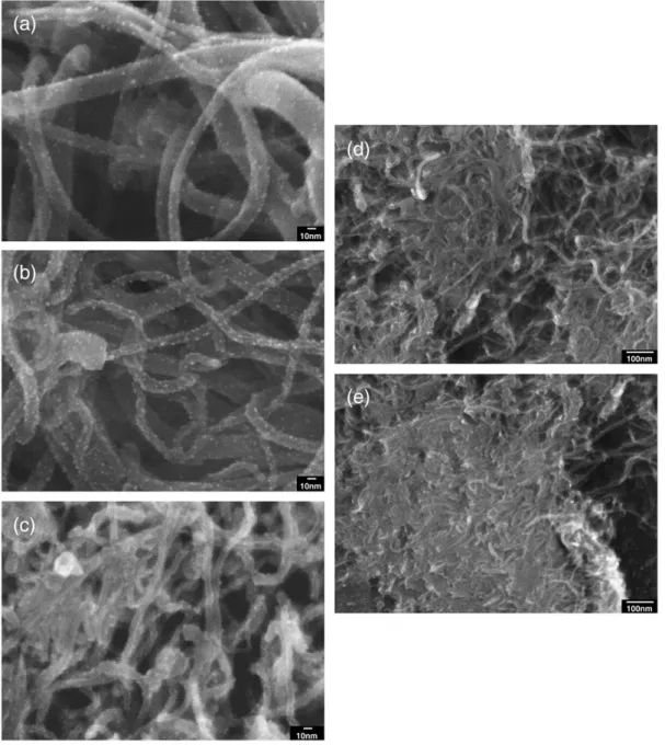
Fig. 2. SEM micrograph of PtRu/CNTs/CC hybrid electrodes, fabricated via EPD process at different applied potentials of (a) 0.1 V, (b) 0.5 V, (c) 1 V, (d) 5 V for 10 min.
Fig. 3. Current density vs. EPD time at different applied potentials.
Fig. 4. CV characteristics of PtRu/CNTs/CC hybrid electrodes, fabricated at different applied potentials, in a solution of 1 M H2SO4at a scan rate of 50 mV/s.
controlled pH. During the EPD process, the applied potential and EPD time were the key parameters in the loading and control of PtRu NPs. Although the high viscosity and high dielectric constant of EG solvent was unsuitable medium for EPD[21], the negatively charge of glycolate surrounded the PtRu NPs promoted the mobility of NPs in EG under the dc electricfield. Most importantly, the applied potential played a significant role in the kinetic control of deposition process. To unravel the influence of applied potential on the deposition behavior in the PtRu colloidal solution, the EPD under various external po-tentials between 0.1 and 5.0 V for 10 min were carried out. As shown inFig. 2, the morphological evolutions of different applied potentials were examined by SEM. It clearly shows that the density of PtRu NPs distribution increased with the applied potential, but the organic
solvent of the surrounding medium disturbed the deposition of NPs at higher potential (N1 V). Theoretically, the PtRu NPs can be deposited with faster rate at higher applied potential, but seriously suffers from the tradeoff in the quality of the deposit. An optimal condition of 0.5 V was concluded to achieve the best uniformity in the NPs-distribution. An attempt has been made to understand the mechanism of EPD process influenced by the applied potential.Fig. 3represented the dependence of the EPD current on the EPD time, at various potentials, to monitor the real-time kinetic behavior of NPs-deposition. The typical deposition characteristics of PtRu NPs on CNTs/CC electrode at constant potential showed a rapid current drop at turn-on potential within the transient period, followed by a gradual reduction to a steady current, which certainly reflected the kinetic behavior of
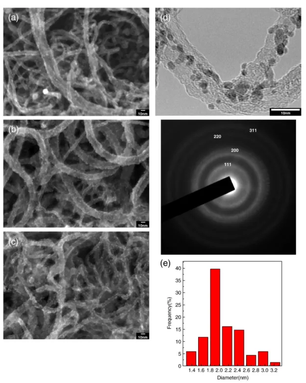
NPs-Fig. 5. SEM micrograph of PtRu/CNTs/CC hybrid electrodes, fabricated at applied potential of 0.5 V for different EPD times of (a) 20 min, (b) 60 min, and (c) 100 min. (d) TEM micrograph of PtRu/CNTs/CC hybrid electrode deposited at 0.5 V for 60 min; the corresponding SAED pattern shown in inset (e) histogram of particle distribution.
deposition as a dependence of the applied potential. Comparison of the steady current values clearly indicated that even if the suspension concentration was kept constant, the greater applied potential can generate higher EPD current. The effect of reduced current at the transient stage, therefore, was not due to the decreasing suspension concentration but was due to a mobility decrease of NPs as a function of EPD time. Such decrease in the mobility of NPs, during constant-potential EPD, can be ascribed to the fact that the glycolate coverage, over the deposited NPs, acted as a shielding protector and have higher electrical resistance than the suspension from which deposition took place. Consequently, as the deposit grew, the available electrical driving force decreased with time. Additionally, in case of the applied potential above 1 V, slight increase of the steady current with time was observed. Under this condition, the bubbles-formation could be observed at the terminal of CNTs/CC electrode. It probably resulted from the water electrolysis or/and electro-oxidation of EG, which can generate oxygen and carbon dioxide, respectively, since the water was one of the products during the preparation of PtRu colloidal solution. The electroactive surface area of Pt electrode was commonly con-ducted by counting the surface sites for hydrogen adsorption, in which the electrical charge density for hydrogen adsorption was known as 210μC·cm− 2 [22]. The effect of the applied potential on electro-chemically active surface area was determined by cyclic voltammetry (CV) measurement in a solution of 1 M H2SO4. The CV plots, which associate with hydrogen adsorption and desorption events were shown inFig. 4. Hence, the total electrical charges involved in hydro-gen adsorption on PtRu/CNTs/CC electrode can be measured easily and preciously from the integration of I–V curve within the potential region of hydrogen adsorption. After dividing the calculated value of “total electrical charges” by 210 μC·cm−2, the electroactive surface area of PtRu/CNTs/CC electrodes was found to be 15.3, 17.1, 14.3, 13.6, and 12.3 cm2, corresponding to the applied potential of 0.1, 0.5, 1, 2.5, 5 V, respectively. At the applied potential of 0.5 V, the largest electroactive surface area can be obtained which reflected the most uniform dis-tribution of PtRu NPs loading, as observed by SEM (Fig. 2b). When the applied potential was over 1 V, the decrease in electroactive surface area can be ascribed to the incorporation of organic solvent that indeed hinders the distribution of PtRu NPs. The optimum potential at 0.5 V was also in agreement with the SEM measurement.
To further increase the PtRu NPs density on CNTs/CC electrode, the influence of the EPD time on the NPs loading amount under optimum potential of 0.5 V was also examined by SEM. As shown inFig. 5, the increased period of deposition could observably result in increased PtRu NPs density on the CNTs surface. Unto the deposition period of 100 min, the organic solvents and gas bubbles still did not appear on the surface of PtRu/CNTs/CC electrodes. Without the perturbative agents, the loading amount of PtRu NPs can be further increased with
increased EPD time under the optimal potential of 0.5 V. Additionally, TEM image showed that the optimal size of PtRu NPs was maintained around 2.08 nm in diameter (Fig. 5d,e). Also shown in the inset of
Fig. 5d was the corresponding selected area electron diffraction (SAED) pattern of PtRu NPs, the ring pattern of which indicated face-centered cubic structure. Therefore, via simple EPD process, the uni-form and dense loading of PtRu NPs with well-controlled small size on CNTs can easily be accomplished, without any requirement of functionalization of CNTs surface, and hence without any unwanted damage/contamination of the electrode.
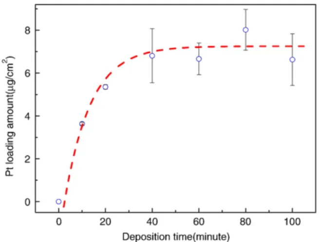
ICP measurements were performed to quantify the loading amount of PtRu NPs, as illustrated inFig. 6. The loading amounts of Pt increase rapidly within the EPD time of 60 min, during which there were sufficient surface sites for NPs-deposition. It implied the controllability of loading amount by EPD time during the initial 60 min. Saturation of the loading amount was observed after the initial 60 min deposition, which was attributed to the self-repulsion of the charged PtRu colloids by PtRu NPs, deposited on electrode-surface. It indicated that the limitation of loading amount was closely dependent on the surface area of the support. Therefore, the amount of controllable NPs loading can easily be enhanced just by increasing the surface area of carbon support. To evaluate the performance of PtRu/CNTs/CC hybrid electrode with different EPD times in the electro-oxidation methanol, the CVs were recorded in 1 M H2SO4+ 1 M CH3OH solution at 25 °C (Fig. 7). In the forward scan the catalysts showed a methanol oxidation peak around 0.68 V (vs. Ag/AgCl) for all samples. The peak current of reverse scan which signified the CO oxidation was obvious. Because the preparation of PtRu/CNTs/CC electrodes didn't include the reduction process, there were partial oxidation states of Ru resulting from sample preparation procedure. However, the ratio of peak current of forward and reverse scan was always larger than one. It implied that the Ru in the catalysts still had beneficial effect on CO poisoning mitigation. The methanol oxidation current enhanced with the
Fig. 6. Actual Pt loading amount as a function of EPD time.
Fig. 7. Performance of PtRu/CNTs/CC hybrid electrode with different EPD times, for the electro-oxidation of methanol, in a solution of 1 M H2SO4+ 1 M CH3COOH at a scan rate
of 50 mV/s.
Table 1
Ratios of metallic state to oxidation state of Pt, corresponding to EPD time, atfixed applied potential of 0.5 Va
Deposition condition Pt/Pt2+ratio
EPD at 0.5 V for 10 min 1.70
EPD at 0.5 V for 20 min 1.69
EPD at 0.5 V for 40 min 1.65
EPD at 0.5 V for 60 min 1.61
EPD at 0.5 V for 80 min 1.21
EPD at 0.5 V for 100 min 1.17
a
increase in the EPD time, i.e. the catalysts loading. At the EPD time of 60 min, the PtRu/CNTs/CC electrode exhibited the highest current density. However over the time of 60 min, the current decreased even though those hybrid electrodes had about the same catalysts loading. Such catalytic behavior for the methanol oxidation process was further explored by X-ray photoelectron spectroscopic (XPS) analysis in order to understand the change in electronic behavior of PtRu NPs with different EPD times.Table 1listed the ratios of metallic state to oxidation state of Pt, showing a slow increase of the oxidation state in the initial 60 min followed by a pronounced increase within 80 to 100 min EPD time. The decrease of methanol oxidation current, therefore, can be ascribed to high ratio of Pt oxidation state, which was reportedly inactive in catalytic reaction[16]. At the optimal condition of 0.5 V for 60 min, a catalytic activity of 1.6 A/cm2/mg in electro-oxidation of methanol can be achieved by the PtRu/CNTs/CC hydride electrode, which was better than the literature report[4,7].
4. Conclusion
In summary, the combination of EPD and EG techniques provided an efficient route to prepare highly dispersed PtRu NPs on CNTs/CC for methanol oxidation. High performance electrodes based on PtRu/ CNTs/CC can be achieved through the control of the applied potential and deposition time during the EPD process. Under the optimum deposition condition, optimal control of particle size and loading amount can be achieved, providing a catalytic activity of 1.6 A/cm2/mg in electro-oxidation methanol reaction, which was highly desirable in many applications including fuel cells and supercapacitors.
Acknowledgements
This research was financially supported by the Ministry of Education, Asian Office of Aerospace Research and Development
under AFOSR, National Science Council, and Academia Sinica, Taiwan.
References
[1] S. Wasmus, A. Kuver, J. Electroanal. Chem. 461 (1999) 14.
[2] D.R. Rolison, P.L. Hagans, K.E. Swider, J.W. Long, Langmuir 15 (1999) 774. [3] S.Lj. Gojkovic, T.R. Vidakovic, D.R. Durovic, Electrochim. Acta 48 (2003) 3607. [4] S.J. Liao, K.A. Holmes, H. Tsaprailis, V.I. Birss, J. Am. Chem. Soc. 128 (2006) 3504. [5] Z.Q. Tian, S.P. Jiang, Y.M. Liang, P.K. Shen, J. Phys. Chem. B 110 (2006) 5343. [6] T. Iwasita, H. Hoster, A. John-Anacker, W.F. Lin, W. Vielstich, Langmuir 16 (2000)
522.
[7] J. Prabhuram, T.S. Zhao, Z.K. Tang, R. Chen, Z.X. Liang, J. Phys. Chem. B 110 (2006) 5245. [8] Y.H. Lin, X.L. Cui, C.H. Yen, C.M. Wai, Langmuir 21 (2005) 11.
[9] Y.G. Lin, Y.K. Hsu, J.L. Yang, S.Y. Chen, K.H. Chen, L.C. Chen, Diamond & Relat. Mater. 18 (2008) 557 (this issue).
[10] C.H. Wang, H.Y. Du, Y.T. Tsai, C.P. Chen, C.J. Huang, L.C. Chen, K.H. Chen, H.C. Shih, J. Power Sources 171 (2007) 55.
[11] H.Y. Du, C.H. Wang, H.C. Hsu, S.T. Chang, U.S. Chen, S.C. Yen, L.C. Chen, H.C. Shih, K.H. Chen, Diamond & Relat. Mater 17 (2008) 535.
[12] C.H. Wang, H.C. Shih, Y.T. Tsai, H.Y. Du, L.C. Chen, K.H. Chen, Electrochim. Acta 52 (2006) 1612.
[13] M.C. Tsai, T.K. Yeh, Z.Y. Juang, C.H. Tsai, Carbon 45 (2007) 383.
[14] Y. Wang, X. Xu, X.Q. Tian, Y. Zong, H.M. Cheng, C.J. Lin, Chem. Eur. J. 12 (2006) 2542. [15] M. Endo, Y.A. Kim, M. Ezaka, K. Osada, T. Yanagisawa, T. Hayashi, M. Terrones, M.S.
Dresselhaus, Nano Lett. 3 (2003) 723.
[16] W.H. Li, X. Wang, Z.W. Chen, M. Waje, Y.H. Yan, J. Phys. Chem. B 110 (2006) 15353. [17] C. Bock, C. Paquet, M. Couillard, G.A. Botton, B.R. MacDougall, J. Am. Chem. Soc. 126
(2004) 8028.
[18] W.Y. Yu, W.X. Tu, H.F. Liu, Langmuir 15 (1999) 6.
[19] H.S. Liu, C.J. Song, L. Zhang, J.J. Zhang, H.J. Wang, D.P. Wilkinson, J. Power Sources 155 (2006) 95.
[20] T.W. Ebbesen, H. Hiura, M.E. Bisher, M.M.J. Treacy, J.L. Shreeve-Keyer, R.C. Haushalter, Adv. Mater. 8 (1996) 155.
[21] L. Besra, M.L. Liu, Prog. Mater. Sci. 52 (2007) 1.