Journal of Physics: Conference Series
PAPER • OPEN ACCESS
Liquid crystal cell with graphene electrodes
To cite this article: V Marinova et al 2017 J. Phys.: Conf. Ser. 794 012009
View the article online for updates and enhancements.
Related content
Analysis of Dynamic Response of Permittivity in a Liquid Crystal Cell with Flow
R Ozaki, K Matsuura, K Kadowaki et al.
-Accurate Determination and Measurement Error of Pretilt Angle in Liquid Crystal Cell
Kwan-Young Han, Tetsuya Miyashita and Tatsuo Uchida
-A New Operation Mode of a Ferroelectric Liquid Crystal Cell with an Asymmetrical Surface Condition
Makoto Yoneya, Katsumi Kondo, Motomi Odamura et al.
-Recent citations
Ion trapping by the graphene electrode in a graphene-ITO hybrid liquid crystal cell
Rajratan Basu and Andrew Lee
Liquid crystal cell with graphene electrodes
V Marinova1,2*, Z F Tong3, S Petrov3, S H Lin3, M S Chen2, Y H Lin2, Y C Lai2, P Yu2 and K Y Hsu2
1
Institute of Optical Materials and Technologies, Acad. G. Bonchev Str 109,
Sofia, Bulgaria
2
Department of Photonics, National Chiao Tung University, University Str.,
1001, Hsinchu 30010, Taiwan
3
Department of Electrophysics, National Chiao Tung University,
University
Str., 1001, Hsinchu, Taiwan
E-mail: [email protected]; [email protected]
Abstract. We demonstrate a graphene-based nematic liquid crystal cells fabricated by photo alignment technique. The modulation characteristics have been measured revealing that photo alignment method shows great potential for protecting the graphene layer on glass substrate during LC device fabrication.
1. Introduction
Liquid crystal displays (LCDs) are among the most important devices in modern life, intensively used in variety of photonics and optoelectronic applications [1]. Essential components for LCDs are transparent and electrically conductive layers. Among them, a solid solution from indium (III) oxide (In2O3) and tin (IV) oxide (SnO2), known as ITO, is the dominant one. Recently, the demand for ITO
thin-film transparent electrodes has dramatically increased. However, a stable supply of ITO may be difficult to be achieved for the recently expanding market for optoelectronic devices because of the cost and scarcity of Indium, the principal material of ITO. Therefore, the development of alternative materials is necessary to resolve this significant problem. Furthermore, ITO deposition is sensitive to the acidic and basic environments and requires complicated technical processing. In this aspect graphene, due to its excellent electrical conductivity, low sheet resistance and very high transparency in a broad spectral range [2,3] appears to be the perfect candidate to replace the ITO contacts.
After the pioneering work of Blake et al. [4] demonstrating the first LC display with one-side graphene electrode, several attempts have been proposed for complete replacement of ITO contacts. For example, high transmittance graphene-based LC cell with performances competitive to ITO-based LC cell have been reported [5], however, the fabrication of graphene-based LC device is problematic due to the mechanical rubbing which damage the graphene layer during the alignment procedure [6].
In this paper, we demonstrate a fabrication of nematic liquid crystal cell with graphene-based electrodes using photo alignment technique. The modulation characteristics of LC cell with graphene electrodes are measured and compared with the similar cell using conventional ITO electrodes. The results reveal that the photo-alignment technique opens a great potential for protecting the graphene
ISCMP IOP Publishing IOP Conf. Series: Journal of Physics: Conf. Series 794 (2017) 012009 doi:10.1088/1742-6596/794/1/012009
International Conference on Recent Trends in Physics 2016 (ICRTP2016) IOP Publishing Journal of Physics: Conference Series 755 (2016) 011001 doi:10.1088/1742-6596/755/1/011001
2. Experimental details and discussion
2.1. Graphene-based LC cell fabrication
Basically the LC device consists of LC layer sandwiched by a pair of glass substrates (figure 1 shows the schematic structure). In such configuration each glass substrate is covered with conductive layer and an alignment layer.
To realize the proposed structure, first the graphene was grown on a Cu foil, using a low-pressure chemical vapor deposition (LPCVD) method [7,8]. Generally, LPCVD is widely used approach to growth high quality graphene, in large area and with controlled thickness [9].The growth process was performed in a quartz tube using 50 sccm high purity hydrogen and 20 sccm methane flow at a temperature of 1000 oC. After completing the growth process, the graphene was transferred on the glass substrates by spin coating a poly(methyl-methacrylate) PMMA on the top of graphene/Cu sheets. After PMMA deposition on the graphene site, the PMMA/graphene/Cu foil was floated on Fe(NO3)3·9H2O solution in order to selectively etch the Cu foil. Subsequently, the resultant film with
PMMA and graphene was transferred on several glass substrates, followed by removal of the PMMA using acetone at 60 °C.
Figure 1. Schematic structure of LCD (Graphene or ITO layer stand as a conductive layer).
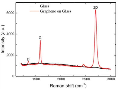
Before assembling the cells, the quality of graphene layer on a glass substrates were verified by Raman spectroscopy analysis. The Raman spectra were collected using a high resolution confocal Raman microscope (LabRAM HR Horiba-Jobin Yvon, HR 800) with 632.8 nm He/Ne-laser excitation under ambient conditions.
The Raman spectra of graphene transferred on a glass substrate is shown in figure 2. As it seen, the peak intensity of characteristics D-band is rather weak which indicates the fewer amounts of defects on graphene surface [10]. Furthermore, the 2D/G ratio is larger than 2 which figure out that over 90% of the area is single layer graphene.
2
ISCMP IOP Publishing IOP Conf. Series: Journal of Physics: Conf. Series 794 (2017) 012009 doi:10.1088/1742-6596/794/1/012009
Figure 2. Raman spectra of graphene layer transferred on a glass substrate
Next, the alignment layer was prepared by spin coating a photo-curable polyimide (PI) layer (Innolux Corporation) on the above graphene-covered glass substrates and illuminated with linearly polarized UV light (wavelength of 365 nm and intensity of 1.6 mW/cm2) for 10 minutes. We note that using the
photo-alignment method the direction of alignment is parallel to the polarization of the UV light [11]. Finally, the empty cells are prepared using 12 m Mylar spacer. The LC molecules (nematic phase E7, Merck) were injected into the empty cell.
In addition, a reference LC cell using conventional ITO contacts with the same thickness was prepared for comparison using standard mechanical rubbing procedure.
2.2. Modulation characteristics
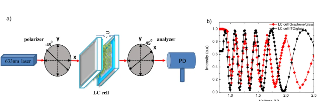
The modulation characteristics were measured by inserting the LC cell between a pair of crossed polarizers as shown at figure 3(a). AC rectangular voltage with f=1 kHz was applied on the device and the power of the transmitted laser beam was monitored by a power meter.
The results are shown in figure 3(b). As it is seen, the transmitted light intensity (I) through the LC cell follows the sinusoidal function of the amplitude of applied voltage due to the phase retardation () provided by the LC molecules, given by the formula [1]
(1)
where Io is the initial output light intensity.
The modulation results for graphene-based LC cell are compared with the ITO-based cell, made as reference sample. As is illustrated in figure 3(b), both LC cells have similar modulation characteristics, with quite similar values of the driving voltages for both cells. Although the LC cell with ITO electrodes demonstrates higher contrast, the oscillation behaviour of the transmitted light intensity as a function of the driving voltage values of both reference cells is very similar.
1500 2000 2500 3000 0 2000 4000 6000 Glass Graphene on Glass D G 2D Raman shift (cm-1) Intensity (a. u.)
ISCMP IOP Publishing IOP Conf. Series: Journal of Physics: Conf. Series 794 (2017) 012009 doi:10.1088/1742-6596/794/1/012009
Figure 3. (a) Experimental set-up for voltage –transmittance measurements and (b) Transmitted light
intensity versus applied voltage for LC cells using graphene contacts and photo-alignment method (rectangular symbols) and ITO contacts and mechanical rubbing method (circle symbols)
3. Conclusion
We demonstrated graphene contacts-based LC cells prepared by using photo-alignment method. The voltage-transmitted characteristics show similar behaviour compared to the ITO reference LC cell prepared using mechanical rubbing. The results indicate that the photo-alignment technique can prevent damage of the graphene layer during the alignment procedure.
Acknowledgements
The financial support by the Ministry of Science and Technology, Taiwan under contracts MOST 103-22221-E-009-079, 104-2221-E-009-164, 103-2911-I-009-516 and AUT Ministry of Education, Taiwan and Bulgarian Science Fund under the project FNI-T-02/26 are gratefully acknowledged. Thanks are due to the Innolux Corporation, Taiwan for providing materials for photoalignment layers deposition.
References
[1] Yeh P and Gu C 2010 Optics of liquid crystal displays (Wiley New Jersey)
[2] Zheng Q and Kim J K 2015 Graphene for Transparent Conductors Synthesis, Properties and Applications (Springer)
[3] Huang X, Zeng Z, Fan Z, Liu J and Zhang Hua 2012 Adv. Mater. 24 5979–6004
[4] Blake P, Brimicombe P D, Nair R R, Booth T J, Jiang D, Schedin F, Ponomarenko L A, Morozov S V, Gleeson H F, Hill E W, Geim A K and Novoselov K S 2008 Nanoletters 8 1704-1708
[5] Wahle M, Kasdorf O, Kitzerow H S, Liang Y, Feng X and Mullen K 2011 Mol. Cryst. Liq. Cryst. 543 187-193
[6] Jung Y U, Park K W, Hur S T, Choi S W and Kang S J 2014 Liquid Crystals 41 101-105 [7] Lai Y C, Rafailov P M, Vlaikova E, Marinova V, Lin S H, Yu P, Chi G C, Dimitrov D,
Sveshtarov P, Mehandjiev V and Gospodinov M M 2016 J. Phys. Conf. Ser. 682 012009 [8] Lai Y C, Yu S C, Rafailov P M, Vlaikova E, Valkov S, Petrov S, Koprinarova J, Terziyska P,
Marinova V, Lin S H, Yu P, Chi G C, Dimitrov D and Gospodinov M M 2014 J. Phys. Conf. Ser. 558 01205
[9] Muñoz R and Gómez-Aleixandre C 2013 Chem. Vapor Depos. 19 297-332
[10] Ferrari C, Meyer J C, Scardaci V, Asiraghi C C, Lazzeri M, Mauri F, Piscanec S, Diang J, Novoselov K. S, Roth S and Geim A 2007 Phys. Rev. Lett. 97 187401
[11] Yaroshchuk Y and Reznikov Y 2012 J. Mater. Chem. 22 286-300
633nm laser polarizer analyzer 450 -450 X X ~ U y y PD a) b) LC cell 0.0 1.0 1.5 2.0 2.5 0.2 0.4 0.6 0.8 1.0 Voltage (V) Int ens ity (a. u) LC cell Graphene/glass LC cell ITO/glass 4
ISCMP IOP Publishing IOP Conf. Series: Journal of Physics: Conf. Series 794 (2017) 012009 doi:10.1088/1742-6596/794/1/012009