Architecture Design of H.264/AVC Decoder with
Hybrid Task Pipelining for High Definition Videos
To-Wei Chen, Yu-Wen Huang, Tung-Chien Chen, Yu-Han Chen, Chuan-Yung Tsai and Liang-Gee Chen
DSP/IC Design Lab, Graduate Institute of Electronics Engineering and Department of Electrical Engineering National Taiwan University, Taipei, Taiwan; Email: [email protected]
Abstract— The most critical issue of an H.264/AVC decoder is the system architecture design with balanced pipelining schedules and proper degrees of parallelism. In this paper, a hybrid task pipelining scheme is first presented to greatly reduce the internal memory size and bandwidth. Block-level, macroblock-level, and macroblock/frame-level pipelining schedules are ar-ranged for CAVLD/IQ/IT/INTRA PRED, INTER PRED, and DEBLOCK, respectively. Appropriate degrees of parallelism for each pipeline task are also proposed. Moreover, efficient modules are contributed. The CAVLD unit smoothly decodes bitstream into symbols without bubble cycles. The INTER PRED unit highly exploits the data reuse between interpolation windows of neighboring blocks to save 60% of external memory bandwidth. DEBLOCK unit doubles the processing capability of our pre-vious work with only 35.3% of logic gate count overhead. The proposed baseline profile decoder architecture can support up to
2048×1024 30fps videos with 217K logic gates, 10KB SRAMs,
and 528.9MB/s bus bandwidth when operating at 120MHz.
I. INTRODUCTION
ISO/IEC Moving Picture Experts Group (MPEG) and ITU-T Video Coding Experts Group (VCEG) formed a Joint Video Team (JVT) to develop the latest video coding standard, H.264/AVC [1]. It can save 25%–45% and 50%–75% of bitrates when compared with MPEG-4 ASP and MPEG-2, respectively. The bitrate saving in baseline profile comes from the new features including multi-frame and variable-block-size (VBS) inter prediction, intra prediction, context-based adaptive variable length decoding (CAVLD), and deblock filter. However, an H.264/AVC decoder requires two times computational power of an MPEG-4 decoder, and four times of an MPEG-2 decoder. Therefore, hardware acceleration for H.264/AVC decoding is a must.
In this paper, there are four critical issues to be addressed. First, the decoding procedures of H.264/AVC are significantly more complex than those in previous standards, making the conventional macroblock (MB) pipelining very inefficient. Second, the context formation of CAVLD is highly depen-dent of prior symbols, bringing tough challenges to parallel processing. Third, the inter prediction with VBS and quarter-pel precision is extrememly hungry for off-chip memory band-width, leading to the system throughput bottleneck. Fourth, the 2-D deblock filter fetches and processes each pixel for many times, requiring a huge amount of on-chip memory bandwidth and a high degree of computing parallelism.
The rest of this paper is organized as follows. In Section II, a hybrid task pipelining scheme is presented to reduce the internal memory size and to highly reuse the external
memory data. Besides, the degrees of parallelism are analyzed. Section III describes three important modules in H.264/AVC decoders. Implementation results are shown in Section IV. Finally, Section V gives a conclusion.
II. SYSTEMARCHITECTURE
A. Hybrid Task Pipelining Architecture
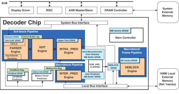
The overall system architecture is shown in Fig. 1. Accord-ing to our software/hardware partition scheme, the sequence parameter set (SPS), picutre parameter set (PPS), and slice headers are parsed by RISC because their symbol rates are very low. The MB-level information including MB headers and prediction residues are decoded by the PARSER Engine. The predicted pixels are generated by the INTER PRED or INTRA PRED Engine according to the MB type. The residues are generated by the IQ/IT Engine. The MB is reconstructed by SUM AND CLIPPING module. Finally, DEBLOCK Engine filters MB pixels and outputs them to the external memory. The buffers between the processing engines are required to separate pipelining stages. In summary, the system architecture is based on a hybrid task pipelining scheme including 4×4-block-level pipelining, MB-level pipelining, and frame-level pipelining. Previous designs of video decoders are usually based on MB pipeline scheme [2]. In H.264, 4×4-block is the smallest element of the prediction block type. The transforms and entropy coding are also based on 4×4-blocks. Based on these characteristics, a 4×4-block pipelining scheme for CAVLD, inverse quantization/inverse transformation (IQ/IT), and intra prediction (INTRA PRED) is proposed with the benefit of less coding latency. It requires only1/24 of buffer size when compared to the traditional MB pipeline architecture.
Figure 2 explains the proposed 4×4-block pipeline schedul-ing. Each box labeled with a number represents a 4×4-block, the horizontal axis represents time, and the boxes of the same time slot denote concurrent pipeline tasks. Following the decoding order, the decoder processes one luma DC block (if existed), 16 luma blocks, two chroma DC blocks, 4 chroma (u) blocks, and finally 4 chroma (v) blocks.
Inter prediction produces the predicted MB pixels from previously decoded reference frames. In H.264, a number of different block sizes can be used for inter prediction— 16×16, 16×8, 8×16, 8×8, 8×4, 4×8, and 4×4. As with intra prediction, the basic processing element of INTER PRED is also a 4×4-block. As shown in Fig. 3(a), due to the six-tap FIR filter for interpolation, 9×9 interger reference pixels
2931
0-7803-8834-8/05/$20.00 ©2005 IEEE.
Intra-Reconstructed /Inter-Residue MB Buffer SRAM
Inter-Predicted MB Buffer SRAM CAVLD Buffer reg
IQ/IT Engine
INTER _PRED Engine
Upper Pels SRAM
DEBLOCK SRAM
QP InIntra SRAM
Motion Info SRAM IntraMode SRAM
Motion Vector Prediction IntraMode
Prediction
IntraMode Reg. Motion Info Reg.
MB IsIntra SRAM INTRA_ PRED Engine Exp-Golomb Decoding PARSER Engine CAVLD
Total Coeff. SRAM
Main Controller
Local Bus Interface 4x4-block Pipeline Macroblock Pipeline Macroblock/ Frame Pipeline 16MB Local External Memory (Ref. frames) Bitstream SRAM
System Bus Interface
Display Driver RISC AHB Master/Slave DRAM Controller System
External Memory AHB
Decoder Chip
SUM_AND_ CLIPPING DEBLOCK EngineFig. 1. Proposed system architecture.
CAVLD INTRA PRED IQ, IT 1 1 1 2 2 2 3 3 3 ... ... ... time Decoding tasks
Fig. 2. Proposed 4×4-block pipeline scheme. Each box represents a 4×4-block. The number on each 4×4-block is the 4×4-block index.
are required for a current 4×4-block. If the block size is larger than 4×4 (in Fig. 3(b), it is a 4×8-block), motion vectors of adjacent 4×4-blocks are the same. Overlapped reference frame pixels of these two 4×4-blocks can be shared and reused to reduce the bandwidth. It should be noted that the probability for large block size is considerably high [3]. The inherent order of 4×4-blocks in the bitstream is the double-z-scan order as illustrated in Fig. 4. Reference frame data reuse will be less efficient if INTER PRED adopts the 4×4-block pipelining scheme and follows the double-z-scan order. For example, block 3 and block 9 in Fig. 4 cannot share reference frame data efficiently under the double-z-scan order. Therefore, INTER PRED should be scheduled to MB-level pipelining with a customized scan order to exploit the reference frame data reuse. All reference frame pixels necessary to inter predict a MB are read from memory in one pass to minimize memory bandwidth.
The basic processing element of H.264 deblock filtering is an MB. After all vertical edges of adjacent 4×4-blocks are filtered, the horizontal edges of adjacent 4×4-blocks are filtered. This data dependency makes 4×4-block pipeline for deblock filter impractical. If deblock operation has to be fit into the 4×4-block pipelining, an extra MB buffer is required because the block scanning order with efficient data reuse of deblock operation is completely different from that of previous stage. As a result, the deblock operation should be done in an MB-based schedule. When H.264 supports Flexible
Reference frame data Current 4x4-block 9 9 Reference frame data Current 4x4-block 9 9 9 (a) (b)
Fig. 3. (a) Inter prediction for a 4×4-block. (b) Inter prediction for one 4×8-block. 10 11 12 13 14 15 16 1 2 3 4 5 6 7 8 9
Fig. 4. Double-z-scan order of 4×4-blocks. The number and the arrow represent the 4×4-block order.
Macroblock Ordering (FMO) and Arbitrary Slice Ordering (ASO), the receiving order of MBs is not raster-scan order anymore, which violates of the scan order of the deblock operation. In the case of FMO and ASO, deblock filter should be scheduled to the frame-level pipelining. If FMO and ASO are not activated, the MBs are still received in raster-scan order, and the MB pipelining scheme can still be adopted.
The pipeline scheduling of the entire decoder is shown in Fig. 5 . MB 1, 2, and 3 are assumed to be inter predicted, while MB 4 is assumed to be an intra predicted MB. When inter predicted type MBs are processed, the intra prediction unit in the 4×4-block pipeline is disabled. On the other hand, when intra predicted type MBs are processed, the inter prediction unit in the MB pipeline is disabled.
B. Parallelism Analysis
Of the three 4×4-block pipeline tasks, CAVLD decodes unfixed number of symbols and takes unfixed cycles, while the
REC time INTER PRED DEBLOCK MB1 MB1 MB1 MB2 MB2 MB2 MB3 MB3 MB3 MB4 MB4 N/A macroblock pipeline 1 2 1 1 2 3 2 3 3 ... ... ... Intra-predicted macroblock 1 2 1 N/A 2 3 N/A 3 N/A ... ... N/A Inter-predicted macroblock CAVLD IQ, IT INTRA PRED 4x4-block pipeline Inter-predicted macroblock Intra-predicted macroblock Zoom into
inter-predicted macroblock
Zoom into intra-predicted macroblock
Fig. 5. Block-level/MB-level pipeline scheduling. N/A means the task is disabled and not available.
Cycles for intra-predicted-macroblock reconstruction
0 100 200 300 400 500 600 0 5 10 15 20 25 30 35 40 45 50 Quantization parameter Cycles Parallelism 1 Parallelism 2 Parallelism 4
Entropy decoder bounded Parallelism bounded
Parallelism for fixed cycle tasks
Typical Usage Sequence : Mobile Calendar
Finely quantized Coarsely quantized
Fig. 6. The cycle count for decoding one intra MB.
other two tasks, IQ/IT and INTRA PRED, take fixed cycles. Assuming CAVLD decodes one symbol per clock cycle, the degrees of parallelism of IQ/IT and INTRA PRED remain to be determined. Here we discuss the degrees of parallelism in terms of module throughput. Different degrees of parallelism lead to different cycle time to complete the task. The simulated cycles to reconstruct an intra type MB for 4x4-block pipelining architecture is shown in Fig. 6. Finely quantized video results in more coefficients for CAVLD, and the total cycle time remains long even if the parallelism of fixed cycle tasks (IQ/IT and INTRA PRED) is increased. In this case, the pipelining system performance is ”CAVLD bounded”. On the contrary, coarsely quantized video results in complementary phenomenon. In this case, the system is bounded by the parallelism of fixed cycle tasks. It should be noted that in our module designs, an M-parallel architecture has M times of throughput, while the induced area overhead is much less than M times [4]. To support 2048×1024 30fps videos, the degrees of parallelism for IQ/IT and INTRA PRED are chosen as 4. INTER PRED produces the same number of predicted pixels as INTRA PRED, so the parallelism of INTER PRED is chosen the same as INTRA PRED.
III. MODULEARCHITECTURE
In this section, we contributed three innovative modules— CAVLD, INTER PRED, and DEBLOCK. For architecture of
NumOfCoeff & NumOfTrailingOnes Table TrailingOnes signs Table Level Table Barrel Shifter Level Buffer
Number of Used Bits
Run Buffer Inverse Scan Output Buffer Bitstream SRAM
Suitable for Multi-symbol Implementation Total Run Table
Run Table
Fig. 7. Hardware architecture for CAVLD. TABLE I
SUMMARY OFSINGLE-SYMBOL ANDMULTI-SYMBOLCAVLD ENGINE
Single-symbol Two-symbol Three-symbol
Area 100% 120% 140%
Cycles Per MB 471 276 212
The quantization parameter is set to 0 to demonstrate the capability of different architecture.
IQ/IT and INTRA PRED module, please refer to the previous work [4].
A. CAVLD
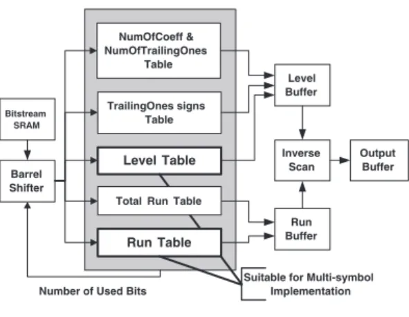
The hardware architecture of CAVLD is shown in Fig.7. Each symbol can be consecutively decoded without bubble cycles. The intuitive parallel processing techniques to speed up CAVLD cannot be applied due to the context-based adaptive nature. In some ultra-high-end or low-power applications, the cycle time available to decode an MB is very limited. In these cases, single-symbol decoding engine for CAVLD appears as the throughput bottleneck of the system. Thus we proposed a multi-symbol decoding engine for CAVLD to overcome this limit. If there are N possible symbols to be decoded, for a two-symbol decoding engine, there will beN2possible joint-symbols, which will be too complicated. After analysis of the CAVLD algorithm, it shows that multi-symbol decoding engine can be much more simplified. There are only two kinds of symbol with high possibility to occur consecutively in bit-stream, which are levels and runs. Building multi-symbol VLD tables for levels and runs, CAVLD can decode consecutive multiple levels or runs in one cycle. Simulation results show that cycle count for CAVLD can be greatly reduced with low area overhead, as shown in Table I.
B. Inter Prediction
In H.264, VBS inter prediction are composed of 4 ×4-blocks. Based on this characteristic, we can design a 4 ×4-block inter prediction unit, and reuse it for larger ×4-block type. The inter prediction process involves six-tap filtering, so 9×9 reference pixels must be loaded for a 4×4-block. As a result, inter prediction demands for large bandwidth and becomes the system bottleneck. Two techniques are proposed to deal with
TABLE II CHIPSPECIFICATION
Proposed C&S [2] Conexant [5] SandVideo [6]
Technology 180nm 130nm 130nm 130nm
Logic Gates 217K 910K 300K N/A
Memory (Internal/External) 10KB/16MB N/A 74KB/24MB N/A
Operating Frequency 120MHz 170MHz 200MHz N/A
Profile baseline baseline(multi-standards) main main
Spec. 2048×1024, 30fps 1920×1080, 30fps 2048×1024, 30fps 2048×1024, 30fps
Sequence : Mobile Calendar
Bandwidth for Inter Prediction
0 100 200 300 400 500 600 700 0 5 10 15 20 25 30 35 40 45 50 Quantization Parameter Bandwidth (MBytes/sec) no reuse data reuse data reuse w/ int. motion vecter
Fig. 8. Bandwidth for inter prediction under different reference frame reuse scheme.
this bandwidth problem. First, reference frame pixels shared by adjacent 4×4-blocks should be reused. Second, if motion vectors point to integer-pixel positions in reference frame, interpolation is not necessary, and less pixels are required, therefore further bandwidth reduction can be achieved. Sim-ulation results in Fig. 8 show that bandwidth can be reduced up to 60% using these two techniques.
C. Deblock Filter
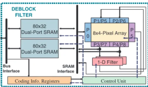
In our previous work [7], we proposed the architecture for an H.264 deblock filter. A parallel-in parallel-out FIR filter and an array of 8×4 8-bit shift registers with reconfigurable data path is implemented to support both horizontal filtering and vertical filtering on the same circuit. In this paper, in order to support high-end levels defined in the standard, a new architecture for deblock filter, shown in Fig. 9, with double throughput is proposed. While the original memory allocation scheme uses only one dual-port SRAM, the proposed double-throughput scheme splits from one dual-port SRAM to two half-sized dual-port SRAMs. By this new architecture, only one additional filter logic is required to double the throughput. The transpose buffer, all information registers, boundary-strength calculating logic remained the same. The induced gate count overhead is only 35.3% compared to our previous work.
IV. IMPLEMENTATIONRESULTS
We described our architecture by Verilog HDL and syn-thesized the circuit using 180nm Artisan CMOS cell library by Synopsys Design Analyzer with critical path constraint set to 8.33ns (120 MHz). The results are shown and compared with other implementations in Table II. Our work has the benefit of lower gate count, lower internal/external memory requirements, and lower operating frequency. Currently, we
80x32
Dual-Port SRAM P8x4-Pixel Array
0 P1/P5 P2/P6 P 5 Control Unit P3/P7 P4/P8 SRAM Interface DEBLOCK FILTER Bus Interface
Coding Info. Registers 80x32 Dual-Port SRAM
1-D Filter 1-D Filter
Fig. 9. Proposed new deblock filter architecture.
only support the baseline profile. In the future, our technology will be improved to 130nm, and the functionality will be extended to the main profile.
V. CONCLUSION
In this paper, we contributed a hardware architecture for H.264/AVC decoders. The major idea is to arrange decoding functions into proper pipelining schedules. Degrees of paral-lelism are also chosen to meet real-time requirements. The external memory bandwidth is greatly reduced due to efficient data reuse scheme. Simulation results show that the processing capability of proposed architecture is to support 2048×1024 30fps videos at 120 MHz, and the silicon area and required frequency are lower than other commercial H.264 decoders.
REFERENCES
[1] J. V. Team, Draft ITU-T Recommendation and Final Draft International
Standard of Joint Video Specification. ITU-T Rec. H.264 and ISO/IEC 14496-10 AVC, May 2003.
[2] H. Y. Kang, K. A. Jeong, J. Y. Bae, Y. S. Lee, and S. H. Lee, “MPEG4 AVC/H.264 decoder with scalable bus architecture and dual memory controller,” in Proc. of Int. Symposium on Circuits and Systems
(ISCAS’04), 2004.
[3] Y. W. Huang, B. Y. Hsieh, T. C. Wang, S. Y. Chien, S. Y. Ma, C. F. Shen, , and L. G. Chen, “Analysis and reduction of reference frames for motion estimation in MPEG-4 AVC/JVT/H.264,” in Proc. of Int. Conf.
on Accoustics, Speech, and Signal Processing (ICASSP’03), 2003, pp. III
– 145–8 vol.3.
[4] Y. W. Huang, B. Y. Hsieh, T. C. Chen, and L. G. Chen, “Hardware architecture design for H.264/AVC intra frame coder,” in Proc. of Int.
Symposium on Circuits and Systems (ISCAS’04), 2004.
[5] Y. Hu, A. Simpson, K. McAdoo, and J. Cush, “A high definition H.264/AVC hardware video decoder core for multimedia SoC’s,” in Proc.
of Int. Symposium on Consumer Electronics (ISCE’04), 2004.
[6] SandVideo, “Sandvideo releases the first h.264 decoder,” in
http://www.prweb.com/releases/2003/12/prweb93434.htm, 2003.
[7] Y. W. Huang, T. W. Chen, B. Y. Hsieh, T. C. Wang, T. H. Chang, and L. G. Chen, “Architecture design for deblocking filter in H.264/JVT/AVC,” in
Proc. of Int. Conf. Mutimedia and Expo (ICME’03), 2003, pp. I – 693–6
vol.1.