國 立 交 通 大 學
資訊科學與工程研究所
碩
士
論
文
以整數線性規劃作為在混合指令集架構
下之暫存器重指派方法達成程式碼減量
Code Size Reduction by Integer Linear Programming for
Register Reassignment in Mixed-Width ISA Processors
研 究 生:陳柏村
指導教授:單智君 博士
以整數線性規劃作為在混合指令集架構下之暫
存器重指派方法達成程式碼減量
Code Size Reduction by Integer Linear Programming for
Register Reassignment in Mixed-Width ISA Processors
研 究 生:陳柏村
Student:Po Tsun, Chen
指導教授:單智君
Advisor:Dr. Jyh-Jiun Shann
國 立 交 通 大 學
資 訊 科 學 與 工 程 研 究 所
碩 士 論 文
A Thesis
Submitted to Institute of Computer Science and Engineering College of Computer Science
National Chiao Tung University in partial Fulfillment of the Requirements
for the Degree of Master
in
Computer Science and Engineering October 2010
i
以整數線性規劃作為在混合指令集架構下之暫
存器重指派方法達成程式碼減量
學生:陳柏村
指導教授:單智君 博士
國立交通大學資訊科學與工程研究所碩士班
摘 要
在嵌入式系統中,程式碼大小是與效能一樣重要的議題,特別是針對記憶體 受限制之系統,因此減少記憶體使用之相關研究亦是蓬勃發展。而其中一種 減少記憶體使用的方式為使用混合指令集架構。這種架構通常提供二種不同 長度的指令集,一般為 16 位元的短指令及 32 位元的長指令。在商業化的 產品中,如 ARM、MIPS、Andes 都提出此種指令集架構,用來減少精簡指令 集架構所產生之機器碼過大問題。我們的研究數據顯示,約有 49% 的指令其 指令格式需至暫存器指定完後,才能決定其指令格式為 16 位元短指令或 32 位元長短令;因此如何在混合指令架構下,妥善指派暫存器是非常重要的。 暫存器重指派主要是藉由重新指定暫存器編號來達成不同目的之優化;在先 前的研究中,在混合指令集架構下之暫存器重指派問題已經被證明是 NP 問 題,因此解決的方法大多也是用 Heuristic 的方式來得出可行解。在此篇論 文研究中,我們使用了整數線性規劃來求解在混合指令架構下之暫存器重指 派問題。在不考慮編譯時間的條件下,我們約可減少 34.4% 的機器碼大小。ii
Code Size Reduction by Integer Linear Programming for
Register Reassignment in Mixed-Width ISA Processors
Student: Po-Tsun Chen Advisor: Dr. Jyh-Jiun Shann
Institute of
Computer Science and Engineering
National Chiao Tung University
Abstract
Code size issue for a memory constrained embedded system is as important as performance. There are many researches that devote to this issue. One way of reducing code size is to exploit compact instruction formats. A mixed-width ISA may provide this kind of feature for the Reduce Instruction Set Computer (RISC) processors. In general, it usually provides two different widths of instruction formats: short and long instruction format. In commercial, ARM, MIPS and Andes all support this feature in their products. From our research, the formats of 49% instructions can be decided only after register assignment. Therefore, the register assignment policy is very important for mixed-width ISA. Register reassignment renumbers the registers in each instruction for specific goals. Register reassignment for mixed-width ISA has been proved to be an NP problem. Some researches have devoted to design heuristic algorithms to find the feasible solutions. In this thesis, we use integer linear programming to solve the register reassignment problem in mixed-width ISA for reducing the code size. On the average, we reduce about 34.4% code size compared to the original program.
iii
誌 謝
首先感謝我的指導教授 單智君老師,在這二年中不論是在報告上或是平日 討論,老師對我們的細心指導及對每一個細節態度,都讓我受益良多。另外也感 謝 徐慰中老師,在每一次的報告中所給與的寶貴意見。同時也感謝我的口試委 員,雍忠教授、楊武教授及金仲達教授。由於教授們的指導與建議,使得這篇碩 士論文更加完整及充實。 裕生學長、奕緯學長,感謝兩位學長在日常的小組討論中給與的建議及討論, 特別是裕生學長,由於有你的細心指導及不厭其煩的與我討論,使得我能更順利 的完成這篇碩士論文。同時也感謝實驗室的學長姐、同學們及學弟妹,因為有你 們的相伴,使得研究這條艱辛的道路走起來更有趣味。 最後,感謝我的雙親及長期陪伴支持我的每一位親友,我在此獻上最大的祝 福及謝意,並謹以此論文獻給各位。 陳柏村 2010/10/14iv
Table of Content
摘 要... i Abstract ... ii 誌 謝... iii Table of Content ... iv List of Figures ... viList of Tables ... viii
Chapter 1 Introduction ... 1
1.1 Observation ... 4
1.2 Motivation and Objective ... 5
1.3 Organization of this thesis ... 6
Chapter 2 Background and Related Work ... 7
2.1 Background ... 7
2.1.1 Register Reassignment Problem ... 7
2.1.2 Calling Convention ... 8
2.1.3 Integer Linear Programming ... 8
2.2 Related Work ... 9
2.2.1 Ku’s Method... 10
2.2.2 Discussion of Ku’s Method ... 13
Chapter 3 ILP Formulation for Register Reassignment MethodⅠ ... 15
3.1 Overview ... 15
3.2 Description of Register Reassignment ... 16
3.3 Notations ... 17 3.3.1 ISA Features ... 17 3.3.2 Function Features ... 19 3.3.3 Reassignment Matrix ... 20 3.4 Formulation ... 20 3.4.1 Objective Function ... 20 3.4.2 Constraints ... 33 3.4.3 Summary ... 35 3.5 Example ... 37 3.5.1 Objective Function ... 40
3.5.2 Register Usage Constraints ... 40
3.5.3 Register Reassignment Constraints... 41
3.5.4 Instruction Operands Constraints ... 41
v
Chapter 4 ILP Formulation for Register Reassignment MethodⅡ ... 45
4.1 Notation... 45 4.1.1 ISA Features ... 46 4.1.2 Function Features ... 47 4.1.3 Reassignment Matrix ... 48 4.2 Formulation ... 49 4.2.1 Objective Function ... 49 4.2.2 Constraints ... 51 4.3 Example ... 52 4.3.1 Objective Function ... 55
4.3.2 Web Usage Constraints ... 55
4.3.3 Register Reassignment Constraints... 56
4.3.4 Web Interference Constraints ... 56
4.3.5 Instruction Operands Constraints ... 60
4.3.6 Reassigning to Small Set Register Constraints ... 61
4.3.7 Callee-Saved Registers Overheads Constraints ... 62
Chapter 5 Experiments ... 65
5.1 Environment ... 65
5.1.1 IBM ILOG CPLEX ... 65
5.1.2 LLVM ... 66
5.1.3 Target Architecture ... 66
5.2 Benchmark Evaluation Results ... 67
5.3 Experiments Discussion ... 70
5.3.1 Discussion of MethodⅠ ... 70
5.3.2 Discussion of MethodⅡ ... 73
Chapter 6 Conclusions and Future Works ... 75
vi
List of Figures
Figure 1-1 Two different mode switch mechanisms: (a) Use mode switch instruction
(b) Use special instruction encoding ... 3
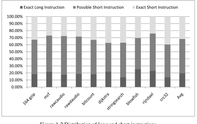
Figure 1-2 Distribution of long and short instructions ... 5
Figure 2-2 Example of neighbor graph ... 13
Figure 3-1 Proposed flow chart of our register reassignment method ... 16
Figure 3-2 Structure of InstTable ... 19
Figure 3-3 Reassignment Matrix ... 20
Figure 3-4 Function layouts after code generation ... 23
Figure 3-5 An example of reassignment a callee-saved register to a callee-saved register ... 26
Figure 3-6 An example of reassignment a callee-saved register to a caller-saved register ... 26
Figure 3-7 An example of reassignment a temporary register to a callee-saved register ... 27
Figure 3-8 An example of reassignment a temporary register to a caller-saved register ... 28
Figure 3-9 An example of reassignment an argument register to a callee-saved register ... 29
Figure 3-10 An example of reassignment an argument register to a caller-saved register ... 29
Figure 3-11 An example of reassignment a return value register to a callee-saved register ... 30
Figure 3-12 An example of reassignment a return value register to a caller-saved register ... 31
Figure 3-13 An example of the reassignment matrix ... 34
Figure 3-14 An MIPS 32 assembly code ... 37
Figure 3-15 Register reassignment results for example 3.5 ... 44
Figure 4-1 Register reassignment results for example 4.3 ... 64
Figure 5-1 Translation rate of uncertain in which format instructions to short instructions ... 68
Figure 5-2 Additional instruction count comparison ... 69
Figure 5-3 Code size reduction comparison ... 70
Figure 5-4 Instruction coverage ratios of top 7 frequent occurrence registers of unlzh ... 71
vii
Figure 5-6 Instruction coverage ratios of the top 7 frequent occurrence registers in CRC ... 73
viii
List of Tables
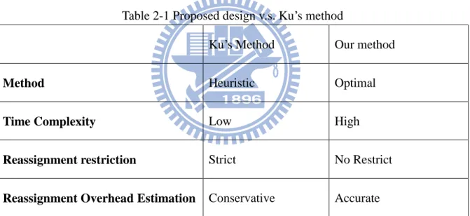
Table 2-1 Proposed design v.s. Ku’s method ... 14
Table 3-1 Summary of reassignment overheads ... 32
Table 3-3 The contents of InstTable ... 39
Table 3-4 Example of reassignment overheads ... 40
Table 4-1 Instruction insertions for callee-saved registers at prologue/epilogue after register reassignment ... 50
Table 4-2 The contents of InstTable ... 54
1
Chapter 1 Introduction
Embedded systems are widely used in many fields, from the hand-held devices to micro-control systems. For the cost and energy consumption consideration, embedded systems usually adopt reduced instruction set computer (RISC) processor in system. However, the features of a RISC processor make the code size larger than complex instruction set computer (CISC) processor. Therefore, many researches have devoted to reduce the code size of a RISC processor. The mixed-width ISA is one of the methods designed for this purpose. It can achieve high code density and low power consumption simultaneously. Processors, for example, ARM, MIPS, and Andes family of embedded cores, support mixed-width ISA [1-3]. MIPS proposed microMIPS as an independent 16- and 32-bit ISA that compatible with original MIPS32 and MIPS64. ARM also has thumb2 as an independent 16- and 32-bit ISA [4-5].
In general, mixed-width ISA processor is a RISC processor with more than one fixed-width instructions sets [6]. Basically, it supports two different kinds of encoding lengths for long instructions (L-Format) and short instructions (S-Format). For instance, in MIPS, 16-bit length is for the short instructions and 32-bit length for long instructions. There are some advantages of mixed-width ISAs; the most well known one is significantly reducing the code size of RISC processors. Moreover, there are some benefits corresponding to the code
2
size reduction such as the improvement instruction cache miss rate and decreasing of the bus traffic between memory and cache. Despite of the great advantages of mixed-width ISA, some limitations of the short format instructions should be considered and we listed as follows:
1. Limited functionalities
S-format instructions are the subset of L-format instructions and for some operations, it may use several S-format instructions to accomplish. The reason is that the operation bit field of S-format instruction cannot specify all the operations and the lengths of others fields are not enough. For example, Thumb is a subset of ARM ISA. 2. Fewer bits for holding the immediate value
Due to ISA format limitation, an immediate value oversized the immediate field of S-format cannot be represented by S-format instruction. In MIPS16e, the length of immediate value filed is 8 bits for some S-format instructions but 16 bits for L-format instructions.
3. Fewer bits for indexing registers
Due to ISA format limitations, the S-format instructions of some mixed-width ISAs cannot access all the registers. In MIPS, there are only 3 bits for indexing registers in 16-bit instruction but 5 bits for indexing registers in 32-bit instructions.
For switching long and short format instructions, there are two commonly used mechanisms as shown in figure 1-1 and we will depict in the following:
3 1. Using mode switch instruction:
Compiler will insert a mode switch instruction between the L-format and S-format instructions. The mode switch instruction gives a hint to the processor which length of the instructions to be processed. To avoid frequently mode switches that cause performance loss, compiler will find contiguous convertible blocks to exploit the S-format instructions. This method is adopted in MIPS16/32 and ARM/Thumb ISA.
2. Using special instruction encoding:
This method uses a bit in an instruction to indicate whether the instruction is L-format or S-format. Compiler or programmer can exploit each instruction which can be converted to the S-format instruction. This method is more flexible than using mode switch instruction. However, this mechanism also reduces an available bit in the ISA. In real word, microMIPS and Thumb2 all adopted this mechanism for the mixed-width ISA. We adopt this mechanism as our design in this thesis.
(a) (b) Figure 1-1 Two different mode switch mechanisms:
(a) Use mode switch instruction (b) Use special instruction encoding
BB1: BB2: j func16 BB1: j funcB main: func16
M
ix
3
2-16
B
it
In
st
s.
… … … … … … … … … …4
1.1 Observation
So far we have introduced the mixed-width ISA: an architecture feature for reducing code size. Figure 1.2 shows the distribution of long and short instructions if we encoded them by a MIPS like hypothetical mixed-width ISA. The experiment environment based on LLVM 2.5, and selected some benchmarks from SPEC2000, MediaBench and MiBench [7-9]. On the average, about 32.79% instructions produced by the compiler without supporting mixed-width ISA can be directly translated to the S-format instructions since these instructions are irrelative register assignments or no immediate field. There are about 19.06% instructions which cannot be translated to short instructions since the immediate value is oversized or no corresponding S-format instructions. Apart from exact long or short instructions, there are still 48.15% instructions uncertain in which formats before assigning registers. The formats of these kinds of instructions are determined by the register number. If there is a good register allocation/assignment algorithm, these instructions can be translated to S-format instructions. It still gave us a strong motivation to design better policy to handle the register assignment issue of mixed-width ISAs. If we may translate as many possibly short instructions to actual exact short instructions as possible, the code size will decrease largely.
5
Figure 1-2 Distribution of long and short instructions
1.2 Motivation and Objective
From the previous section, it is revealed that register assignment is important for exploiting S-format instructions. Register assignment can be considered in register allocation or by inserting an optimization phase after register allocation. Previous researchers have proposed register allocation methods for mixed-width ISA processors [10-11]. However, they did not consider some important issues such as calling convention or register coalescing in their algorithms. In fact, the goal of register allocation algorithms tries to allocate variables to physical registers with minimized spilling. To make more instructions convert to S-format, it should assign more registers which can be indexed by S-format instructions. However, this two different goals may counteract by each other such that we can neither minimize the spilling and nor assign registers which can be indexed by S-format instructions adequately.
0.00% 10.00% 20.00% 30.00% 40.00% 50.00% 60.00% 70.00% 80.00% 90.00% 100.00%
6
Therefore, we adopted another approach, reassigning register after register allocation. In this paper, we proposed two register reassignment methods to reduce the code size. In the first method, we reassign each used register in a function by once. For the second method, we relax the restriction of the first method by allowing the register can be reassigned more than once if the live-cycle is not overlapped.
Our objective is using the integer linear programming to formulate the register reassignment problem for mixed-width ISA processors to find the optimal translation rate of S-format instructions to reduce the code size.
1.3 Organization of this thesis
We will discuss the background knowledge and related work in Chapter 2. Two register reassignment methods by integer linear programming are introduced in Chapter 3 and 4. Chapter 5 is the experiment results and Chapter 6 is the conclusion and future work.
7
Chapter 2 Background and Related Work
In this chapter, we give an overview of the background knowledge for our design. Previous researches that devoted to code size reduction for mixed-width ISA are also introduced. One previous work for code size reduction by register reassignment for mixed-width ISA processors would be presented in detail and compared with ours.
2.1 Background
Some important background knowledge will be presented in following subsections including register reassignment, calling convention and integer linear programming.
2.1.1 Register Reassignment Problem
Register reassignment, also called register renumbering, can be regarded as an optimization phase after register allocation or as post-compilation. Register reassignment for mixed-width ISA has been proved to be an NP-Complete problem [12]. It reassigns registers of the given assembly code or binary code for some special purposes. The goal of register reassignment is diversity such as optimizing for code size or power consumption and so on. The unit of register reassignment can be a whole program, a function, or a basic block. Each kind of units has different advantages and is useful for different optimization purposes. In our model, the reassignment unit is a function. Since different function may have different reassignment results, it may cause the problem of the violation of calling convention.
8
2.1.2 Calling Convention
Calling convention is a scheme for the way of passing parameters and receiving return values between caller and callee. There are some important issues required to consider: (i) where parameters and return values are placed; (ii) the order of passing parameters; (iii) how to separate tasks between caller and callee such as setting stack pointer for function call; and (iv) which registers can be used directly without saving by callee. Different architectures may have different calling convention schemes and some target machines provide special instructions to improve the efficiency of handling calling convention. Register reassignment may lead the result of the program incorrect if not obeying the rule of the calling convention. Further discussion will be presented in Chapter 3.
2.1.3 Integer Linear Programming
Linear programming is a mathematical method to find the optimal solution under the given constraints. Linear programming has been used in a variety of areas such as computer science, management science, and so on. It formulates a problem with one objective function and one or several linear constraints. The solution of a linear programming problem must satisfy all the constraints to get the best solution. If an additional requirement that all variables of linear equations must be integer is added to linear programming, then it becomes integer linear programming (ILP). Integer linear programming has been proved to be an NP-hard
9
problem. The canonical form of the integer linear programming is listed as follows:
Another variation of integer linear programming is binary integer linear programming (BILP). BILP is an integer programming problem that contains only binary variables and is also called 0-1 integer linear programming. In this thesis, we will use BILP to model our register reassignment problems.
2.2 Related Work
Most of the previous researches to reduce code size for mixed-width ISA with mode switch instructions have proposed different kinds of compilation methods [13-16]. These mechanisms require finding contiguous convertible block for translating to short instructions and insert mode switch instructions between those blocks. It may cause the two following situations: the code size reduction rate cannot be deeply exploited and the mode switch instruction may lead performance losses. Our approach adopts the mixed-width ISA with special instruction encoding that allows the freeform of mixing short and long format instructions. Hence, the above problems are not needed to address in our method.
For the mixed-width ISA with special instruction encoding, Tobias J. K. Edler von Koch et al. proposed a feedback-guided approach that cooperated instruction selection and register allocation methodology to exploit the short instructions of original program [17]. Their
10
method based on three steps; the first step is IR annotation phase that maps mid-level intermediate representation (MIR) to low-level intermediate representation (LIR) by giving preference to short format instructions and annotates extra spill or move code to mid-level intermediate representation. The next step maps virtual registers to physical registers and then decides the LIRs inserted for reducing register pressure. The third step is feedback-guided code generation that deactivates the LIRs produced for reducing register pressure and reproduces the LIRs with long format preference. Subsequently register allocation is performed, and finally, native code interleaving with long and short format instructions are emitted. Although this is a very creative method and improved the performance, this method still suffers from high register pressure such that the code size reduction rate is not ideal.
Our method reduces code size by register reassignment. Register reassignment for mixed-width ISA has been proved as an NP-Complete problem [12]. One previous research of code size reduction by register reassignment has proposed heuristic methods to solve the problem [18]. In our method, we put efforts on using ILP to model the register reassignment problem of mixed-width ISA to find the optimal solution of code size reduction under the given constraints. We will present this related work in the next subsection.
2.2.1 Ku’s Method
In Ku’s heuristic methods [18], there are three main phases: 1. Register selection
11 2. Mapping and reassignment assessment 3. Instruction insertion
For the register selection phase, they proposed two register selection methods which interchange the selected registers with small set registers. Note that the small set register is a set of registers which S-format instructions can be indexed. Those methods are:
1. Selection registers by the priority that based on registers’ usage counts
2. Selection registers by the priority that based on registers’ usage counts and neighbor graph.
The first method is very simple. It counts the number of times for each register used in the input function. The usage count of each register is regarded as the priority of the register for mapping into the small set registers which S-format instruction can be indexed.
Obviously, the first method is too trivial. To increase the opportunity of the used registers appeared in the same instruction, the second method build a new data structure called neighbor graph for manipulating the priority of the candidate registers. The neighbor graph is a special data structure with vertex, edge, weight and priority.
A vertex of a neighbor graph stands for a register number used in the input function and an edge between two vertices represents that these two registers have appeared in same instructions. The weight on an edge is the appearance counts of the two registers. The priority of a vertex is initialized by the usage count of a register. Once a register is selected to map
12
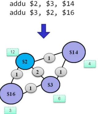
into small register set, the priorities of other vertices which connected with the selected register will be updated by adding the weight of the edge of the selected register to increase the opportunity of related registers. Figure 2-2 is an example of the neighbor graph. Assume that there are two instructions and four used registers, $2, $3, $14, and $16 are used. The initial priorities of these four registers are 12, 6, 4, and 3. For the first instruction, we can find $2, $3, and $14 appeared. Therefore, these three registers form three vertices and there are three edges connected with each other. Moreover, the weight of these three edges is 1. For the next instruction, $2, $3, and $16 appear in the same instruction. Since $16 didn’t appear in previous instruction, we add a new vertex for it and insert two edges between $2, $16 and $3, $16. $2 and $3 have appeared in previous instruction, thus, we only need to increment the weight of edge between $2 and $3 by one.
The next phase is mapping and reassignment assessment. In this phase, the selected registers will be mapped to small register set. The mapping rules are: if the selected registers belong into small set registers, it would be mapped to itself without changing. Otherwise, these registers are mapped from highest to lowest priority through interchanging selected registers with the rest of small set registers. After mapping completion, it started out analyzing the mapping result of a function to determine whether it is valuable to reserve. In consideration of calling convention, it may need to insert some code before and after each function call. Therefore, it may make the code size increased. In Ku’s method, the mapping
13
result is accepted only if the code size reduction was larger than the extra overheads.
The final phase is designed for dealing with the calling convention problem. As we know, register reassignment may violate the calling convention, so it has to insert some code to keep the correctness of the program. For the different categories of registers such as caller-saved or callee-saved, each category has different code insertion rules.
Figure 2-2 Example of neighbor graph
2.2.2 Discussion of Ku’s Method
Ku’s method is very simple and efficient. However, for our purpose, it may be too rough
to solve the problem. We discuss the drawbacks of his method in this subsection.
The first drawback of Ku’s method is that it didn’t deeply consider the reassignment overheads. Although the registers are selected according the usage count and neighbor-graph, , his method did not consider the calling convention overheads while selecting registers.
14
Another important issue is that it interchanged the registers of mapping pairs. This is an easy way to deal with the selected registers that map to the small set registers. However, as we have mentioned in previously, different reassignment combinations may have different reassignment costs under the calling convention. Therefore, interchanging the mapping pair may not cover all possible cases. The other is that this method does not analyze the liveness of the registers such that the calling convention overheads cannot be computed accurately. Brief comparisons between Ku’s method and our method are listed in table 2-1.
Table 2-1 Proposed design v.s. Ku’s method
Ku’s Method Our method
Method Heuristic Optimal
Time Complexity Low High
Reassignment restriction Strict No Restrict
15
Chapter 3 ILP Formulation for Register
Reassignment MethodⅠ
In this chapter, we will present how to model register reassignment problem as an integer linear programming. Firstly, an overview of the proposed design and the assumptions of our model are given. After the notations are defined, we will discuss all the details of our model.
3.1 Overview
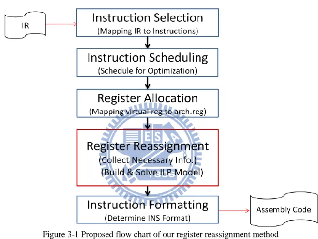
Figure 3-1 shows the proposed design of our register reassignment method. After compiler front-end processing, it produces intermediate representation, (IR) and then, enters into back-end processing. The first stage of back-end processing is instruction selection, which maps IR to target instructions. The second stage is instruction scheduling which takes responsibility for arranging instructions order to reducing stalling or hazard. Then register allocation maps virtual registers to architecture registers. We add a register reassignment phase after register allocation. In this phase, we analyze each instruction of a function and construct the control flow graph in order to computing the liveness information of the physical registers. Besides the liveness information, we compute the reassignment overheads here. Then, we apply our ILP model for register reassignment is applied to produce the constraints and objective function. After an integer program is produced, a third party ILP solver library is used to solve the problem. Finally, we retrieve the results of register
16
reassignment from the solver and the instruction formatting is called to determine the correct format for producing the assembly code. We will present the details of the ILP model in the following sections.
Figure 3-1 Proposed flow chart of our register reassignment method
3.2 Description of Register Reassignment
In this subsection, we will introduce the assumptions, input and output of our ILP method 1. We assume that our target architecture has only two kinds of instruction widths, one long instruction and one short instruction formats. Input of our model is the instructions of a function. The basic register reassignment unit of our method is a function. All the instructions of a function, except those with certain long or short format by arbitrary register assignment,
17
are analyzed. To simplify the problem, we also make an assumption in our first method that each register can only be reassigned to only one register after reassignment. After solving the problem, the produced reassigned register numbers will be used to rewrite the corresponding instructions.
3.3 Notations
The necessary definitions used in our model will be introduced in this section and are classified into ISA features, function features and reassignment matrix.
3.3.1 ISA Features
ISA features related to our model are (i) the target register file, (ii) ISA format, (iii) calling convention, and (iv) classifications of instructions.
Two sets and one function defined for target register file are described as follows:
∙RegisterSetA:
s
et of all the physical registers except special purpose registers in the targetarchitecture.
∙RegisterSetS: the set of all the physical registers which can be indexed by S-format
instructions.
∙isSmallReg(Reg), Reg RegisterSetA: a boolean function which represents whether the
given register will be reassigned to RegisterSetS.
The following variables are related to ISA format. ∙InstSizelong: the number of bytes of a long instruction.
18
∙InstSizeShort: the number of bytes of a short instruction.
∙SavedSize: the number of saved bytes when a long instruction is translated to a short
instruction.
The following sets are related to the calling convention.
∙CalleeSavedRegs: the set of the physical registers saved by callee. ∙CallerSavedRegs: the set of the physical registers saved by caller.
∙TempRegs: the set of physical registers which are used for storing temporary value. ∙ArgRegs: the set of physical registers which are used for passing arguments. ∙RetRegs: the set of physical registers which are used for passing return values.
The following sets defined for the classification of input instructions.
∙L_INS: the set of certain L-format instructions. An instruction which has no equivalent
short format instruction or has oversized immediate value for the equivalent short format instruction belongs to this category.
∙S_INS: the set of certain S-format instructions. An instruction which has an equivalent short
format instruction by arbitrary register assignment belongs to this set.
∙U_INS: the set of instructions each of which may be either L-format or S-format according
to the register assignment. This kind of instructions is the input of our register reassignment method.
19
3.3.2 Function Features
In this subsection, we define the variables or sets to represent function features. Those are (i) register usage of a function and (ii) register number used by each instruction of the function.
∙RegUsed: the set of registers used in the function. ∙RegNotUsed: set of registers not used in the function.
∙RegOpndCount(Inst), Inst U_INS: a function which returns the number of register
operands of an uncertain format instruction Inst.
∙Inst, InstU_INS: instruction variable of each U_INS. Inst = 1 when Inst can be converted
to S-format instruction after reassignment.
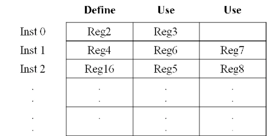
∙InstTable(Inst, k), Inst U_INS; 1≤ k ≤ RegOpndCount(Inst): a function that returns the
kth register number used by Inst. Figure 3.2 shows the structure of InstTable. For example, if we use InstTable(Inst1, 1), this function will return Reg4 as the output.
20
3.3.3 Reassignment Matrix
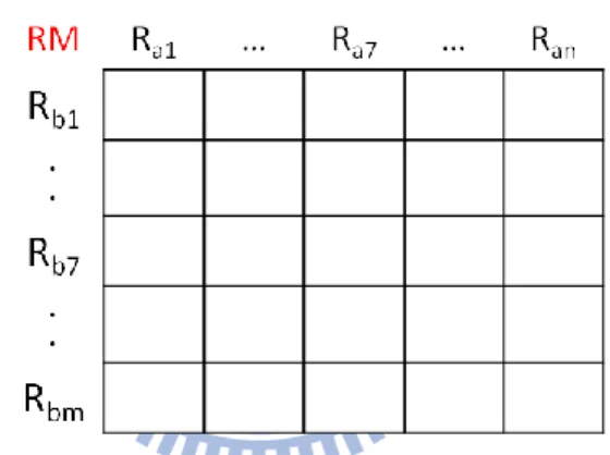
To easily define the constraints for our model, we first introduce a special matrix called reassignment matrix RM. Figure 3.3 shows the structure of an RM. For each row of RM, Rbi,
1≤ i ≤ m, stands for the register number before register reassignment; for each column of RM,
Raj, 1 ≤ j ≤ n, stands for the register number after register reassignment. Each element in RM
is denoted as Xi,j. The Xi,j is define as following:
Xi_j: i, j RegisterSetA: each element of RM, Xi_j = 1 if register i reassigned to register j
Figure 3-3 Reassignment Matrix
3.4 Formulation
After defining the necessary notations used in our ILP model, we present the model for register reassignment problem in this section. We first show the objective function and then introduce the constraints of register reassignment.
3.4.1 Objective Function
If all the register operands of an L-format instruction belong to small set registers, it can be represented by S-format instruction and thus the code size is reduced. However,
21
reassigning registers may also make program incorrect. Since the basic reassignment unit of our model is a function, it means that different functions may have different reassignment results. In other words, the results may violate the calling convention such that the program is incorrect. Therefore, we may need to insert extra code to make our program correct. However, code insertion counteracts the benefits of the register reassignment, i.e., it is a trade-off between the both. Hence, the objective function of our model is expressed as shown in Eq. (1):
CRshort represents code size reduction and Reassignmentoverheads shows the extra code insertion
for the calling convention.
A. CR
shortThe formulation of CRshort is listed as following:
The above is a nonlinear equation when the register operands of an instruction are larger and equal than two. For this kind of nonlinear boolean function, we can use linearization method to deal with it through replacing the nonlinear part of the function by new variables and adding new constraints to linearize this objective function [19]. The modified objective function after linearization is listed in the following.
22
The added constraints are listed as follows:
B. Reassignment Overheads
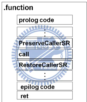
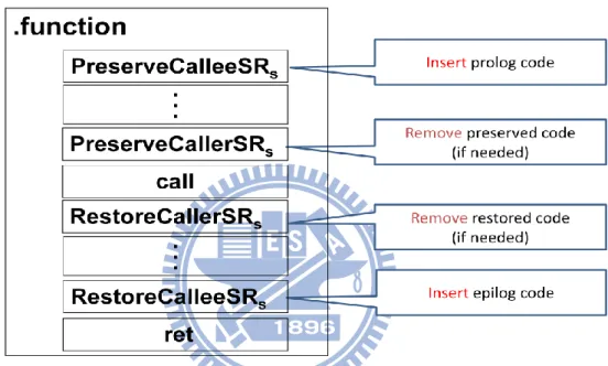
Register reassignment may violate the rule of calling convention since each function may have different reassignment results. Therefore, we may need to insert extra code to keep the correctness of the program. In our model, possible register reassignment overheads of each function can be computed in advance. To deal with the calling convention, we classify the general purpose registers into two categories according to whether the registers which will be preserved and not preserved across function call. These two categories are callee-saved registers and caller-saved registers. In addition, caller-saved registers can further be classified into temporary registers, argument registers and return value registers. Different solution of register reassignment would introduce different overheads. To explain the case of reassignment overheads analysis, a conceptual basic function layout after compiler code generation like Figure 3-4 is used. After compiler completing register allocation, the virtual registers will be mapped to the physical registers. Compiler will insert prolog code and epilog code to preserve and restore the callee-saved register used in current function, respectively.
23
Moreover, if the content of caller-saved registers would be used after a function call in current function, compiler will insert preserved code before the function call and retrieved code after function call. In a RISC processor, the calling convention define the argument registers or return value registers to pass parameters or receive the return values. For analyzing the reassignment overheads, those are important and affect the reassignment overheads significantly.
Figure 3-4 Function layouts after code generation
To compute reassignment overheads, we need to know the type of registers before and after reassignment, the function prototype and the liveness of each used register. In assembly code, function prototype information is very hard to retrieve or analyze. In this thesis, we implement our design in the LLVM compiler [22] to retrieve the necessary information such as function prototype. The other important information we need to know is live range of each used physical registers. To achieve this goal, we construct the control flow graph to compute
24
the live-in, live-out, define and use information of each instruction of the function to calculate to calculate liveness of each used register.
The variables used to check the register type before and after reassignment are defined as follows:
∙isCalleeToCallee(Rbi,Raj), Rbi, Raj RegisterSetA: a boolean function which returns whether
a callee-saved register is reassigned to a callee-saved register.
∙isCalleeToCaller(Rbi,Raj), Rbi, Raj RegisterSetA: a boolean function returns whether a
callee-saved register is reassigned to a caller-saved register.
∙isTempToCallee(Rbi,Raj), Rbi, Raj RegisterSetA: a boolean function returns whether a
temporary register is reassigned to a callee-saved register.
∙isTempToCaller(Rbi,Raj), Rbi, Raj RegisterSetA: a boolean function returns whether a
temporary register is reassigned to a caller-saved register.
∙isArgToCallee(Rbi,Raj), Rbi, Raj RegisterSetA: a boolean function returns whether an
argument register is reassigned to a callee-saved register.
∙isArgToCaller(Rbi,Raj), Rbi, Raj RegisterSetA: a boolean function returns whether an
argument register is reassigned to a caller-saved register.
∙isRetToCallee(Rbi,Raj), Rbi, Raj RegisterSetA: a boolean function returns whether a return
25
∙isRetToCaller(Rbi,Raj), Rbi, Raj RegisterSetA: a boolean function returns whether a return
value register is reassigned to a caller-saved register.
The following definitions are the overheads for the reassignment of different types of registers:
∙CostofCalleetoCaller: overheads of reassignment callee-saved to caller-saved registers. ∙CostofCalleetoCallee: overheads of reassignment callee-saved to callee-saved registers. ∙CostofTemptoCallee: overheads of reassignment temporary to callee-saved registers. ∙CostofTemptoCaller: overheads of reassignment temporary to caller-saved registers. ∙CostofArgtoCallee: overheads of reassignment argument to callee-saved registers. ∙CostofArgtoCaller: overheads of reassignment argument to callee-saved registers. ∙CostofRettoCallee: overheads of reassignment return value to callee-saved registers. ∙CostofRettoCaller: overheads of reassignment return value to caller-saved registers.
Now we start out presenting the reassignment overheads computation. We will discuss each reassignment case by case.
Case 1: Reassignment of a callee-saved register.
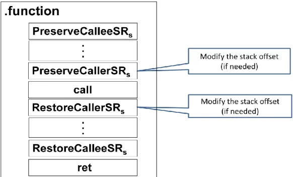
For reassigning a callee-saved register to a callee-saved registers, we may modify the stack offset only since the callee-saved register has been preserved at the prolog and restored at epilog, respectively. The modification of code is shown in Figure 3-5.
26
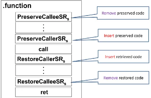
Figure 3-5 An example of reassignment a callee-saved register to a callee-saved register For reassigning a callee-saved register to a caller-saved register, we need to remove the code for preserving and restoring callee-saved register at prologue and epilogue. Also, for each function call in the current function, if the live ranges of original callee-saved registers cross the function call, the preserved and restored code of the register before and after the function call should be inserted. The modification of code is shown in Figure 3-6.
27 Case 2: reassignment of a temporary register.
For reassigning a temporary register to a callee-saved register, it needs to insert code at prologue and epilogue for preserving a callee-saved register. If a temporary register spill/reload the value before/after each function call, we need to remove the code. Figure 3-7 shows an example of a temporary register reassigned to callee-saved registers.
Figure 3-7 An example of reassignment a temporary register to a callee-saved register For reassigning a temporary register to a caller-saved register, if a temporary register has been preserved and retrieved before/after each function call, only the stack offset need to be modified and no insertion of code is required. Figure 3-8 shows the example of reassignment temporary registers to caller-saved registers.
28
Figure 3-8 An example of reassignment a temporary register to a caller-saved register Case 3: reassignment of an argument register
For reassigning an argument register to a callee-saved register, we need to insert code at prologue and epilogue for preserving and restoring the content of the callee-saved register and we also need to insert an instruction to move the argument of the current function to the reassigned register. If the argument register has been preserved and retrieved before and after each function call, it should be removed. For each function call, it also needs to check whether the argument register has been used for passing parameter to the called site. If it is used, a move instruction has to be inserted to move the value to the argument register. Figure 3-9 shows an example of reassignment an argument register to a callee-saved register.
29
Figure 3-9 An example of reassignment an argument register to a callee-saved register For reassigning an argument register to a caller-saved register, we have to insert move instructions for an argument passed into the current function and parameter passed to its function call. If the caller-saved register spills/reloads the value before/after function call, the stack offset should modified. Figure 3-10 shows an example of the reassignment of an argument register to a caller-saved register.
Figure 3-10 An example of reassignment an argument register to a caller-saved register Case 4: reassignment of a return value register
30
For reassigning a return value registers to a callee-saved register, the code insert is similar to that of an argument register except the place of code insertion. If the function has to return a value, an instruction needs to be inserted to move the return value from the reassigned register to the return value register. Another case is that for each function call in the function, if the called function has return value, it has to move the return value from the return value register to the reassigned register. Figure 3-11 shows the example of the reassignment of a return value register to a callee-saved register.
For reassigning a return value register to a caller-saved register, the code insertion policy is the same as we depicted in the previous paragraph. There is one thing different: if the return
Figure 3-11 An example of reassignment a return value register to a callee-saved register value register preserved/retrieved before/after each function call, it has to modify the stack offset to make sure that the value is spilled to the correct stack place. Figure 3-12 shows an
31
example of reassignment a return value register to a caller-saved register. The summary of the reassignment overheads of all possible cases is shown in Table 3-1.
32
Table 3-1 Summary of reassignment overheads
After RRA
Before RRA
Callee-saved Register Caller-saved Register
Callee-saved Register
1.May modify stack offset 1.Remove prologue/epilogue 2.Insert preserved Caller 3.Insert retrieved Caller
Temporary Register
1.May insert prologue/epilogue
2.May remove preserved/retrieved code
1.May modify stack offset
Argument Register
1.May insert prologue/epilogue
2.May remove preserved/retrieved code 3.May insert move instruction before
each function call
4.May insert move instruction after prolog
1.Modify stack offset
2.May insert move instruction before each function call 3.May insert move instruction
after prolog
Return Value Register
1.Insert prologue/epilogue
2.May remove preserved/retrieved code 3.May insert move instruction after
each function call
4.May insert move instruction before function return
1.Modify stack offset
2.May insert move instruction after each function call 3.May insert move instruction
33
According to the cases analysis described above, the equationof the reassignment overheads is expressed as follows: Note that each overhead is all computed in advanced.
3.4.2 Constraints
We describe the constraints for the method 1 in this subsection. 1. Registers usage constraints:
If a register Rbi is used before reassignment, it should be reassigned to one and only one
register Raj after reassignment.
34
reassignment but it can be reassigned by other registers. 2. Register reassignment constraints
For each register Raj after reassignment, we restrict that it is reassigned by one register.
To clearly illustrate the constraints, the following example demonstrates how to use the reassignment matrix to build the constraints. Assume that a fictitiousarchitecture only has four registers and two kinds of instruction widths, long and short formats. The long format instruction can access all the registers and the short format can only access the first three registers. The RegisterSetA = {$r1, $r2, $r3, $r4} and RegistersetS = {$r1, $r2, $r3}. Give a
function that uses register $r1, $r2, $r4. In this case, RegUse = {$r1, $r2, $r4} and RegNotUse = {$r3}. The constraints corresponding to reassignment matrix are shown in Figure 3-13.
Figure 3-13 An example of the reassignment matrix
3. Instruction operands constraints
As mentioned in 3.4.1, these two constraints are added to linearize the objective function.
Ra1 Ra2 Ra3 Ra4
Rb1 ∑ RM[Rb1,Rai] = 1
Rb2 ∑ RM[Rb2,Rai] = 1
Rb3 ∑ RM[Rb3,Rai] = 0
Rb4 ∑ RM[Rb4,Rai] = 1
35 For each Inst U_INS,
4. Reassigning to small set register constraints
This constrains check whether the register after reassignment belongs to the small set register.
3.4.3 Summary
Finally, we give a brief summary of our objective function and constraints
Objective function
36
Constraints
1. Register usage constraints:
2. Register reassignment constraints:
3. Instruction operands constraints:
4. Reassigning to small set register constraints:
37
3.5 Example
We give an example to illustrate our register reassignment method by ILP in this section. We input a simple MIPS assembly code in Figure 3-14 and we will use this example to explain how to build ILP model for register reassignment. Note that the funcA takes one parameter as input. 1 lw $4 4($sp) 2 lw $8 8($sp) 3 add $9 $4 $8 4 sub $10 $9 $4 5 addi $4 $10 2 6 lw $25 %got(funcA)($gp) 7 jalr $25 8 lw $11 4($sp) 9 andi $12 $11 5 10 addi $13 $12 1 11 ori $2 $13 -1 12 jr $31
Figure 3-14 An MIPS 32 assembly code
Here we use MIPS as our target architecture. The sets related to MIPS architecture are defined as follows: RegisterSetA = {$1, $2, …, $25} RegisterSetS = {$1, $2, …, $7} CalleeSavedRegs = {$16, $17, …, $23} CallerSavedRegs = {$2, $3, …, $15, $24, $25} ArgRegs = {$4, $5, $6, $7}
38 RetRegs = {$2, $3}
TempRegs = {$8, $9, …, $15, $24, $25}
InstSizelong = 4 bytes
InstSizeshort = 2 bytes
SavedSize = 2 bytes
We analyze the input assembly code and define the sets related to the function features listed as follows:
U_INS = {Inst1, Inst2, Inst3, Inst4, Inst5, Inst8, Inst9, Inst10, Inst11}
S_INS = {Inst7, Inst12}
L_INS= {Inst6}
InstSizelong = 4 bytes
InstSizeshort = 2 bytes
SavedSize = 2 bytes
RegUsed = {$2, $4, $8, $9, $10, $11, $12, $13, $25}
RegNoUsed = {$1, $3, $5, $6, $r7, $14, $15, $16, $17,…, $24} Reg, Reg RegsisterSetA: register variable
39 InstTable of U_INS is defined in Table 3-3.
Table 3-3 The contents of InstTable
Inst # Opcode RegOpnd Def RegOpnd Use 1 RegOpnd Use 2
Inst1 lw $4 Inst2 lw $8 Inst3 add $9 $4 $8 Inst4 sub $10 $9 $4 Inst5 addi $4 $10 Inst8 lw $11 Inst9 andi $12 $11 Inst10 addi $13 $12 Inst11 ori $2 $13
The reassignment overheads of used registers are listed in Table 3-4 and are all constants. $4 and $2 are used for passing parameter and receiving return value according to MIPS calling convention. If $4 is reassigned, a move instruction should be inserted before function call. Therefore, it leads overheads. If $2 is reassigned, a move instruction should be inserted before function return. Note that a register reassigned to itself has no overheads.
40
Table 3-4 Example of reassignment overheads
Register Reassign to Caller-saved registers Reassign to Callee-saved registers $2 2 bytes 10 bytes $4 2 bytes 10 bytes $8 0 bytes 8 bytes $9 0 bytes 8 bytes $10 0 bytes 8 bytes $11 0 bytes 8 bytes $12 0 bytes 8 bytes $13 0 bytes 8 bytes $25 0 bytes 8 bytes
3.5.1 Objective Function
Maximize2∗Inst1+2∗Inst2+2∗Inst3+2∗Inst4+2∗Inst5+2∗Inst8+2∗Inst9+2∗Inst10+ 2∗Inst11 – 2∗(X2_1+X2_3+X2_4+…+ X2_15+X2_24+X2_25) – 10∗ (X2_16+X2_17+…+X2_23) – 2∗(X4_1+X4_2+ X4_3+ X4_5+…+X4_15+X4_24+X4_25) – 10∗(X4_16+X4_17 +…+X4_23) – 8∗ (X8_16+X8_17+…+X8_23) –8∗ (X9_16+X9_17+…+X9_23) –8∗ (X10_16+X10_17+…+X10_23) – 8∗ (X11_16+X11_17+…+X11_23) – 8 ∗ (X12_16 + X12_17+…+X12_23) – 8 ∗ (X12_16 + X12_17+…+ X12_23) – 8 ∗ (X13_16 + X13_17+…+X13_23) – 8 ∗ (X25_16 + X25_17+…+X25_23)3.5.2 Register Usage Constraints
X2_1+X2_2+X2_3+X2_4+X2_5+…+X2_24+X2_25 = 1
X4_1+X4_2+X4_3+X4_4+X4_5+…+X4_24+X4_25 = 1
41 X9_1+X9_2+X9_3+X9_4+X9_5+…+X9_24+X9_25 = 1 X10_1+X10_2+X10_3+X10_4+X10_5+…+X10_24+X10_25 = 1 X11_1+X11_2+X11_3+X11_4+X11_5+…+X11_24+X11_25 = 1 X12_1+X12_2+X12_3+X12_4+X12_5+…+X12_24+X12_25 = 1 X13_1+X13_2+X13_3+X13_4+X13_5+…+X13_24+X13_25 = 1 X25_1+X25_2+X25_3+X25_4+X25_5+…+X25_24+X25_25 = 1
3.5.3 Register Reassignment Constraints
X1_1+X2_1+X3_1+…+X24_1+X25_1 ≤ 1 X1_2+X2_2+X3_2+…+X24_2+X25_2 ≤ 1 X1_3+X2_3+X3_3+…+X24_3+X25_3 ≤ 1 X1_4+X2_4+X3_4+…+X24_4+X25_4 ≤ 1 . . . X1_24+X2_24+X3_24+…+X24_24+X25_24 ≤ 1 X1_25+X2_25+X3_25+…+X24_25+X25_25 ≤ 1
3.5.4 Instruction Operands Constraints
Inst1 – Reg4 ≤ 0 Reg4 – Inst1 ≤ 0
42 Reg8 – Inst2 ≤ 0
Inst3 – Reg9 ≤ 0 Inst3– Reg4 ≤ 0 Inst3– Reg8 ≤ 0
Reg9 + Reg4 + Reg8 – Inst3 ≤ 2 Inst4 – Reg10 ≤ 0
Inst4 – Reg9 ≤ 0 Inst4 – Reg4 ≤ 0
Reg10+Reg9 + Reg4 – Inst4 ≤ 2 Inst5 – Reg4 ≤ 0
Inst5 – Reg10 ≤ 0
Reg4 + Reg10 – Inst5 ≤ 1 Inst8 – Reg11 ≤ 0
Reg8 – Inst8 ≤ 0 Inst9 – Reg12 ≤ 0
Inst9 – Reg11 ≤ 0
Reg12 + Reg11 – Inst9 ≤ 1 Inst10 – Reg13 ≤ 0
43 Reg13 + Reg12 – Inst10 ≤ 1
Inst11 – Reg2 ≤ 0 Inst11 – Reg13 ≤ 0
Reg2 + Reg13 – Inst11 ≤ 2
3.5.5 Reassigning to Small Set Register Constraints
Reg1 – X1_1– X1_2– X1_3– X1_4– X1_5– X1_6– X1_7 = 0 Reg2 – X2_1– X2_2– X2_3– X2_4– X2_5– X2_6– X2_7 = 0 Reg3 – X3_1– X3_2– X3_3– X3_4– X3_5– X3_6– X3_7 = 0 Reg4 – X4_1– X4_2– X4_3– X4_4– X4_5– X4_6– X4_7 = 0 . . . Reg24 – X24_1– X24_2– X24_3– X24_4– X24_5– X24_6– X24_7 = 0 Reg25 – X25_1– X25_2– X25_3– X25_4– X25_5– X25_6– X25_7 = 0
We input this example to ILP solver, the final result is that we can save 14 bytes after register reassignment. Except $2, all the other registers belong to RegisterSetS after register
reassignment. The final result is listed as follows:
∙X2_2 = 1, X4_4 =1, X8_7 =1, X9_6 =1, X10_10=1, X11_5 =1, X12_3 =1, X13_1=1,X25_25=1
Except instruction 4 and 5, the input instructions all become S-format instructions after register reassignment. Figure 3-15 shows the final result.
44 1 lw $4 4($sp) 2 lw $7 8($sp) 3 add $6 $4 $7 4 sub $10 $6 $4 5 addi $4 $10 2 6 lw $25 %got(funcA)($gp) 7 jalr $25 8 lw $5 4($sp) 9 andi $3 $5 5 10 addi $1 $3 1 11 ori $2 $1 -1 12 jr $31
45
Chapter 4 ILP Formulation for Register
Reassignment MethodⅡ
In this chapter, we will present an extended method which relaxes the register reassignment constraint of the method 1 mentioned in Chapter 3. In the method 1, each register used in a function is restricted to be reassigned to exactly one register. In this extended method, if the live ranges of the registers do not overlap, they can be reassigned to a same register. Therefore, the liveness information of the physical registers should be collected for register reassignment. For computing liveness, we use the web, which is a set of uses and definitions of physical registers in the statements of the function [20]. Each physical register may have several webs. We apply the backward data-flow analysis to build the def-use chain and merge the def-use chains with same use to form the webs. After building the webs, we need to analyze the interference between the webs. Two webs are called interfered if one is live in the definition of another. We use this rule to build the interference constraints to prevent the interfered webs to be reassigned to the same register. In Section 4.1, we first give the notation used in the method 2. In Section 4.2 we will present the ILP formulation for this method. Finally, we will use an example to illustrate this method.
4.1 Notation
46 will be used in this model.
4.1.1 ISA Features
The following sets, variables and functions are the same with the Subsection 3.3.1. We listed it as follows:
∙RegisterSetA:
s
et of all the physical registers except special purpose registers in the targetarchitecture.
∙RegisterSetS: the set of all the physical registers which can be indexed by S-format
instructions.
∙isSmallReg(W), W Webs: a boolean variable function which represent whether the given
web will be reassigned to RegisterSetS.
The following variables are related to ISA format. ∙InstSizelong: the number of bytes of a long instruction.
∙InstSizeShort: the number of bytes of a short instruction.
∙SavedSize: the number of saved bytes when a long instruction is translated to a short
instruction.
The following sets are related to the calling convention.
∙CalleeSavedRegs: the set of the physical registers saved by callee. ∙CallerSavedRegs: the set of the physical registers saved by caller.
47
∙ArgRegs: the set of physical registers which are used for passing arguments. ∙RetRegs: the set of physical registers which are used for passing return values.
The following sets defined for the classification of input instructions.
∙L_INS: the set of certain L-format instructions. An instruction which has no equivalent
short format instruction or has oversized immediate value for the equivalent short format instruction belongs to this category.
∙S_INS: the set of certain S-format instructions. An instruction which has an equivalent short
format instruction by arbitrary register assignment belongs to this set.
∙U_INS: the set of instructions each of which may be either L-format or S-format according
to the register assignment. This kind of instructions is the input of our register reassignment method.
4.1.2 Function Features
We make the definitions of three new sets for the webs and list as follows: ∙Webs: the set of all webs in a function.
∙WebsRegi, iU_INS: the set of register operands of instruction i.
∙WebsInterferencei_j, iRegUsed, j is the set of webs of register i: the set of webs which
interfere with the web, Wi_j.
The following notations are the same with Subsection 3.3.2 ∙RegUsed: the set of registers used in the function.
48
∙RegOpndCount(Inst), Inst U_INS: a function which returns the number of register
operands of uncertain format instruction Inst.
∙Inst, InstU_INS: instruction variable of each U_INS. Inst = 1 when Inst can be converted
to S-format instruction after reassignment.
∙InstTable(Inst, k), Inst U_INS; 1≤ k ≤ RegOpndCount(Inst): a function that returns the
web number of kth register number used by Inst.
For the callee-saved registers used in a function after register reassignment, we define the variables as follows:
∙CalleeUseReg, Reg CalleeSavedRegs: variables for checking whether callee-saved
registers are used after reassignment.
∙CalleeNotUseReg, Reg CalleeSavedRegs: variables for checking whether callee-saved
registers are not used after reassignment.
4.1.3 Reassignment Matrix
In 3.4.2, we have shown the structure of reassignment matrix (RM). Each row and column of RM represents the register number. In Method 2, we modify this RM such that each row of RM stands for the webs of a function. We defined RM and variables used in Method 2 as follows:
∙Xi_j_k, i RegUsed, j the set of webs of register i, k RegisterSetA: each element of the
49
∙Wi_j, i RegisterSetA, j the set of webs of register i: the jth web of register i before
reassignment. Wi_j = 1 if the jth web of register will be reassigned to the small set registers
after reassignment.
4.2 Formulation
In this section, we present the formulation of the second ILP model. First, we show the objective function and constraints of the model.
4.2.1 Objective Function
Our objective function is to maximize the code size reduction: CSR, when all the constraints are satisfied. CSR is comprised of two parts: CRshort and ReassignmentOverheads.
1. CRshort
CRshort is the saved size by translating L-format instruction to S-format instruction.
2. ReassignmentOverheads
50
3. ProEpilogCalleeSR: we need to check whether callee-saved registers are used after reassignment. There are four cases for callee-saved registers to determine the code insertion at prolog and epilog. Table 4-1 presents the code insertion for callee-saved registers at prologue and epilogue.
Table 4-1 Instruction insertions for callee-saved registers at prologue/epilogue after register reassignment
After Reassignment Before
Reassignment
Used NotUsed
Used No Insertion Remove
Prologue/Epilogue
NotUsed Insert
51
4.2.2 Constraints
In Subsection 3.4.2, we have shown the constraints for method one. For the method two, we relax the register reassignment constraints such that each register can be reassigned more than once. Meanwhile, we also set a new constraint for the interfered webs. The constraints are listed as follows:
1. Webs usage constraints
For Wi_j Webs, Wi_j should be reassigned to one and only one register Rj
2. Register reassignment constraints
For each Reg RegisterSetA, Reg can be reassigned any times by Wi_j
3. Webs interference constraints
For Wa_b WebsInterferencei_j, Wa_b and Wi_j cannot reassigned to the same register
(4)
4. Instruction operand constraints For each Inst U_INS,
52
5. Callee-saved registers overheads constraints: these constraints check whether each callee-saved register has been reassigned.
– (7) –
6. Reassigning to small set register constraints
4.3 Example
We give an example to illustrate our register reassignment method by ILP in this subsection. Here we use the same example defined in Section 3.5. Here we also use MIPS as our target architecture; therefore, the target-dependent set would not be defined again.
The following sets are related to the input function.
U_INS = {Inst1, Inst2, Inst3, Inst4, Inst5, Inst8, Inst9, Inst10, Inst11}
S_INS = {Inst7, Inst12}
L_INS= {Inst6}
RegUsed = {$2, $4, $8, $9, $10, $11, $12, $13, $25}
RegNoUsed = {$1, $3, $5, $6, $r7, $14, $15, $16, $17,…, $24}
53 WebsInterference2_1 = {W13_1} WebsInterference4_1 = { } WebsInterference4_2 = {W10_1} WebsInterference8_1 = {W4_1} WebsInterference9_1 = {W4_1, W8_1} WebsInterference10_1 = {W9_1, W4_1} WebsInterference11_1 = { } WebsInterference12_1 = {W11_1} WebsInterference13_1 = {W12_1} WebsInterference25_1 = {W4_2}
Wi_j, Wi_j Webs: webs variable.
Xi_j, i Webs, j RegsisterSetA: Xi_j=1 if Web i reassigns to register j.
CalleeUseReg, Reg CalleeSavedRegs: CalleeUseReg =1 if Reg is used after
reassignment.
CalleeNotUseReg, Reg CalleeSavedRegs: CalleeNotUseReg =1 if Reg is not used after