receiver, which is a spatial–temporal matched filter implemented in the frequency domain. To form a beam pattern, we calculate the spatial frequency spectra of received signals on the antenna array using fast Fourier transform (FFT). After FFT beamforming, a bank of FFT-based matched filters is used to perform code matching. Afterward, the code-matched signals are summed up with maximal-ratio combining through a spatial–temporal channel-matched filter implemented in the frequency domain. This 2-D RAKE receiver includes a channel sounder that is used to estimate the spatial and temporal channel impulse response parameters, such as delays, directions of arrivals, and complex gains of multipath components. Monte Carlo simulations have been used to evaluate the receiver bit-error rate performance in both static channel and mobile radio channel environments. Simulation results show that the RAKE receiver performs well in both kinds of channels.
Index Terms—Fast Fourier transform (FFT) beamforming, two-dimensional (2-D) RAKE receivers.
I. INTRODUCTION
W
IDE-BAND code-division multiple access (WCDMA) has been regarded as the most important access method for third-generation wireless communication systems [1], [2]. In code-division mutliple access (CDMA) systems, all multiple-access signals overlap in both frequency and time. Therefore, multiple-access interference (MAI) is the major degrading factor that limits system capacity. To increase system capacity, we can reduce or cancel the MAI from other users. One commonly used method to reduce MAI is to apply sector antennas at a base station to suppress the MAI from other sectors [3]. This MAI isolation concept can be generalized by applying a spatial filter to take advantage of inhomogeneity in the directions of the arrival of users. For example, an antenna array has been suggested to form a beam pattern toward a desired user and to filter out the MAI from other directions [4], [5]. On the other hand, a CDMA system uses a RAKE receiver to optimally combine the received signals from different radio propagation paths [6]. A conventional RAKE receiver with a single antenna only makes use of the temporal characteristicManuscript received November 24, 2001; revised March 25, 2004 and July 12, 2004. The review of this paper was coordinated by XXXX.
S. Y. Wang is with the Industrial Technology Research Institute, Hsinchu, Taiwan (e-mail: [email protected]).
C. C. Huang is with the National Chiao Tung University, Hsinchu, Taiwan (e-mail: [email protected]).
C. C. Quek is with the Realtek Semiconductor Corp., Hsinchu, Taiwan (e-mail: [email protected]).
Digital Object Identifier 10.1109/TVT.2004.836894
only with different delays in time, but also with different di-rections of arrival (DoA). Recently, research efforts have been conducted in order to combine an antenna array with a RAKE receiver [7]–[15]. A two-dimensional (2-D) RAKE receiver adopting space–time (S–T) signal processing will hopefully take advantages of both spatial and temporal diversity in the reception and improve system capacity considerably. In [16], the capacity improvement was studied for cellular CDMA systems with antenna arrays installed at a basestation.
In general, a 2-D RAKE receiver applies an antenna array to perform spatial filtering and a bank of correlators or matched filters to perform temporal filtering [7], [8], [12]–[15]. In such systems, S–T signal processing can be conducted separately. The DoA of a user is first estimated; then, the antenna array adjusts the phase shift of each antenna element to form a beam pattern toward the estimated DoA direction. The temporal fil-ters are signature-waveform matched filfil-ters. A number of tech-niques are available to estimate the DoA, such as the Fourier beamforming method, the MUSIC algorithm, etc. [17]. Fourier beamforming has the drawback of resolution limitation. The subspace methods (e.g., the MUSIC algorithm) are able to make much more precise DoA estimation, but have the restriction that the number of antenna elements needs to be greater than the number of interference signals from other users or their mul-tipath signals. In CDMA systems, each user has a unique sig-nature waveform. Therefore, a sigsig-nature matched filter can be used to generate an output signal of temporally resolved paths for each user. Consequently, the subspace methods can be used to find the DoAs of those temporally resolved paths [12], [15]. In order to integrate S–T signal processing together, joint S–T processing methods have also been suggested in the literature [9]–[11]. An optimum receiver for a user is a spatial–temporal whitened matched filter based on criteria such as maximum signal-to-noise ratio (SNR) [10].
In this paper, we propose a 2-D RAKE receiver architec-ture with fast Fourier transform (FFT)-based matched filtering. Here, we consider an uplink CDMA system in which a pilot signal, which is associated with a data signal, is used for channel sounding. This 2-D RAKE receiver is in reality a spatial–tem-poral 2-D matched filter. In order to reduce the computation complexity, all the signal processing are performed in the spa-tial–temporal frequency domain. Previous analysis and simula-tion results have shown that CDMA interference signals in the spatial domain can be considered to be spatial white Gaussian random variables, even when a small number of users with a moderate angle spread coexist in the system [12], [13]. In this case, the optimum combining of antenna array signals can be
further simplified to a standard beamforming method that ex-ploits the DoA of the desired user only. Therefore, our 2-D RAKE receiver adopts beamspace transform in the spatial do-main by calculating the FFT of the array signal vector to form multiple fixed beam patterns. For each fixed beam, an FFT-based RAKE receiver is used to match the spreading code of the desired user. We then combine the energy of multipath signals in both space and time. Two banks of FFT-based matched filters are used to perform code despreading and channel matching, respectively. This 2-D RAKE receiver also includes a channel sounder, which estimates the spatial–temporal channel charac-teristics such as delays, DoAs, and complex gains of major mul-tipath components.
This paper describes the operation and evaluates the perfor-mance of the proposed 2-D RAKE receiver architecture. In Sec-tion II, we describe both a system model and a 2-D channel model for uplink transmissions. The details of the FFT-based Fourier beamforming and the 2-D RAKE receiver, including channel sounding, are covered in Section III. Computer simu-lation results are presented in Section IV. Finally, a conclusion is given in Section V.
II. SYSTEMDESCRIPTION
We now consider a CDMA uplink communication system. Assume that a cell is divided into three 120 sectors. Each sector of the cell is equiped with a linear equally spaced (LES) antenna array. Each mobile station transmits a spread-spectrum signal. Without loss of generality, we only consider the case of a single user and treat the interference from a large number of other users as Gaussian noise [18].
The transmitted direct-sequence spread-spectrum (DSSS) signal consists of a data signal and a pilot signal. User data bits are carried in the data signal using binary phase-shift keying (BPSK). The unmodulated pilot signal is used for channel sounding. The transmitted equivalent baseband signal is denoted by
(1)
where
transmission power;
pilot signal signature waveform; th information bit ; data signal signature waveform; bit period of transmitted signals.
Two levels of code spreading are adopted for the transmitted signal. A mutually orthogonal code, such as the Walsh code, can be used as a channelization code for the first-level code spreading to differentiate among the pilot and data signals. Let the channelization codes for the pilot and data signals be de-noted and , respectively. Each user is identified by a second-level spreading code, i.e., its own scrambling code . Here, all the channelization codes and scrambling codes are as-sumed to be equal-length short codes and synchronized with the transmitted information bits; that is, the periods of all spreading codes overlap with the information bit periods. The pilot signal
signature waveform and the data signal signature waveform can be written as
(2) where
length of the spreading code sequences; chip period of spreading codes;
chip waveform with zero intersymbol interference (ISI), e.g., a raised-cosine response with a rolloff factor 1.
Next, we introduce the propagation channel model. Instead of using a conventional channel model, which only models the temporal characteristics of a channel in terms of parameters such as path delays, path amplitude, and phase distributions, we incorporate a spatial–temporal (2-D) channel model that also models the spatial characteristics of the channel, including di-rection of arrival (DoA), angle of spread (AoS), and the antenna array geometry [4], [9]. We assume that our spread spectrum signal is a wide-band signal such that multiple propagation paths of the channel can be resolved. On the other hand, this signal is a narrow-band signal with respect to the delay span introduced by the antenna aperture. For simplicity, here we show only a fixed 2-D channel model. The model will be extended to a stochastic 2-D model when time variations are taken into account (more detail is given in Section V).
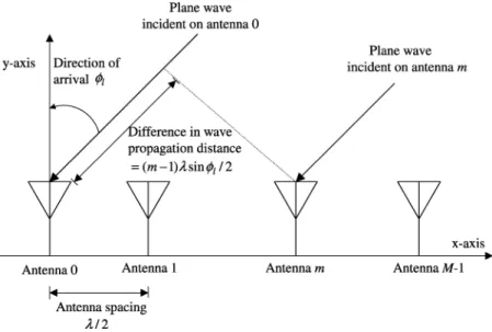
Fig. 1 shows the configuration of an LES antenna array in which a path labeled by is received from a direction . Sup-pose that the size of the antenna array is and the spacing be-tween two neighboring antennas is set to half wavelength . The vector form of the channel impulse response for the th path on the LES antenna array is
(3) where , , and are the array manifold vector, the complex gain, and the delay of the th path, respectively. The array man-ifold vector characterizes the phase lag of the plane wave propagation, which can be determined by the antenna array ge-ometry and the DoA of the arriving wave. With the antenna la-beled 0 as a reference point of the LES antenna array, can be written as
(4) where denotes the Hermitian operation. For modeling mul-tipath propagation, the vector form of the 2-D channel impulse response can be modified as
Fig. 1. Configuration of an LES antenna array.
where indicates the number of dominant multipath compo-nents.
The received equivalent baseband signals on the antenna array is
(6) where is an additive white Gaussian noise (AWGN) vector. Multiple access interference from other users and thermal noise are all lumped together and modeled as an equivalent AWGN [12], [13], [16]. Here, we assume that the noise is spatially
temporally white, i.e., , where
is the noise variance and is the identity matrix.
III. TWO-DIMENSIONALRAKERECEIVERWITHFFT-BASED
MATCHEDFILTERING
A. Fourier Beamforming Using a Discrete Fourier Transform (DFT)
With conventional Fourier beamforming, the weights (phase shifts) on each antenna element are adjusted to steer the antenna beam pattern to a particular direction in order to achieve the maximum SNR gain in the received signal. In order to facili-tate digital signal processing, the received signals on the antenna array are sampled and become discrete-time signals. For conve-nience, the discrete-time received signals on the antenna array
are denoted here as a vector .
According to the property of Fourier beamforming, the array weight vector for a direction of arrival can be given as [17]
(7) and the array output is
(8)
TABLE I
SPATIALFREQUENCYuVERSUS THEDOA (M = 16)
Equation (8) can be regarded as the spatial frequency spectra with respect to the DoA . As DFT is normally used to calculate the frequency spectra of a discrete time signal, the same DFT formula can be used to calculate the spatial frequency spectra. For the signals arriving on the antenna array, the spatial fre-quency spectra can be caculated as
(9) Note that the DFTs of will effectively form multiple-antenna beams to different directions [19]. Comparing (8) and (9), we can find the relationship between DoA and spatial frequency
from the arguments of the two exponents, i.e.,
(10) An example for the case is shown in Table I. Note that, in this table, each spatial frequency of the DFT corresponds to a particular DoA. Furthermore, to reduce the computation burden, we can use the FFT algorithm to calculate the DFT of the signals arriving on the antenna array.
B. Two-Dimensional RAKE Receiver Architecture
In this section, we propose a 2-D RAKE receiver that is im-plemented as a spatial–temporal 2-D matched filter. To reduce computation complexity, the spatial–temporal matched filter is
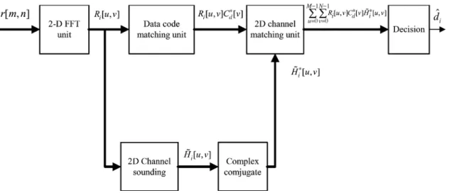
Fig. 2. Conceptual block diagram of an FFT-based 2-D RAKE receiver.
Fig. 3. Simplified block diagram of an FFT-based 2-D RAKE receiver.
realized by FFT-based matched filtering. A conceptual block diagram of the 2-D RAKE receiver is shown in Fig. 2. The spa-tially sampled signals, i.e., the received signals on the antenna array, are transformed using FFT to form antenna beam patterns. In each beam direction, a one-dimensional (1-D) FFT-based RAKE receiver is used to process the received signal [20]. With this method, an FFT-based matched filter and a channel sounder are first used for data code depreading and channel estimation, respectively. An FFT-based spatial–temporal channel-matched filter is then used to combine the energy of the received paths according to the maximal-ratio combining principle.
Fig. 3 shows the simplified block diagram of the 2-D RAKE receiver with FFT-based matched filtering. The equivalent
base-band received signals on the antenna array are first sampled to become discrete time signals. Note that in the block diagram, a 2-D FFT operation is first carried out to calculate the spa-tial–temporal frequency spectra of the received signals. Here, we assume that our system is bandlimited to the chip rate . To reduce the computation load of the 2-D FFT, the sampling rate is chosen to be the Nyquist rate, i.e., the chip rate [21]. The discrete time equivalent baseband received signal on the antenna is denoted by , where and are the antenna index and the discrete sampling time index, respectively. This discrete time equivalent baseband received signal is segmented for -point 2-D FFT computation. Here, we assume that the time window of 2-D FFT computation is synchronized with
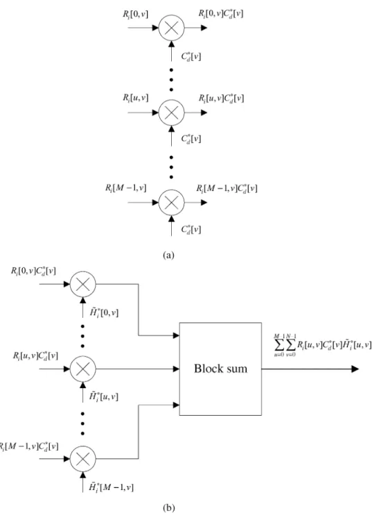
Fig. 4. (a) Bank of FFT-based data-code matched filters in the data-code matching unit. (b) FFT-based spatial–temporal channel-matched filter in the 2-D channel-matching unit.
the received symbol time. As a result, the output of 2-D FFT computation for the th symbol can be written as
DFFT
(11)
for and , where
DFFT denotes the 2-DFFT operation and where th symbol representation of ; FFT of the pilot spreading code
;
FFT of the data spreading code ;
spatial–temporal frequency spectra of the channel for the th symbol;
2-D FFT of the AWGN (including interference). After the 2-D FFT computation, is used to detect data in the upper arm of Fig. 3. For each beam direction in the spatial frequency spectra (i.e., FFT beamforming to a direction parameter ), is applied to an FFT-based data code matched filter to achieve data-code despreading. Fig. 4(a) shows a bank of FFT-based data-code matched filters in the data-code matching unit. The output of the bank of
matched filters is for and
. Using a multiplier instead of a transversal filter to implement a data-code matched filter reduces the computation complexity considerably.
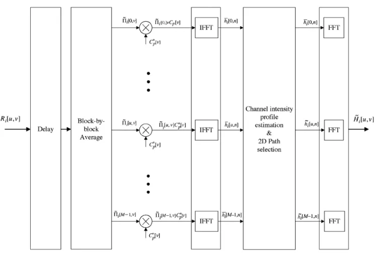
Fig. 5. Block diagram of channel sounding.
After code despreading, an FFT-based spatial–temporal channel-matched filter is used to combine the energy of the re-ceived paths in different beam directions. This channel-matched filter functions as a maximal ratio combiner. If the interference is assumed to be uncorrelated (i.e., spatial–temporal white), the maximal ratio combiner will maximize the SNR of the combined signal [22]. Therefore, the channel-matched filter is an optimal receiver in a spatial–temporal white noise en-vironment. Fig. 4(b) shows the FFT-based spatial–temporal channel-matched filter in the 2-D channel-matching unit. The coefficients of the channel-matched filter are just the com-plex conjugates of the estimated spatial–temporal frequency spectra of the channel . The data-code despreading
output is simply multiplied by for
and . Because the
whole signal-processing chain of the 2-D RAKE receiver is done on a symbol-by-symbol basis and because the pilot and data signals are synchronized, the exact channel-matched point is just the first point of the channel-matching output in the time domain. According to the property of FFT, we can calculate the channel-matched point output (the decision statistic) for the th data symbol by summing up the frequency domain channel-matching results, i.e,
(12)
Then, the data information can be detected by determining whether the real part of is larger or smaller than zero, as BPSK is used here as an example.
C. Channel Sounding
On the other hand, is sent to the lower arm in Fig. 3 to estimate the spatial–temporal frequency spectra of the channel. The channel-sounding method is described next.
The block diagram for channel sounding is shown in Fig. 5. A simple block-by-block first-order infinite impulse re-sponse (IIR) filter is used to average out interference plus noise and estimate the spatial–temporal frequency spectra of the pilot signal, i.e.,
(13)
for and , where a
parameter is used to adjust the time constant of the filter in order to track the channel-fading variations. After the IIR filter, we use a multiplier for each beam direction in the spatial-fre-quency spectra to achieve pilot code despreading and to obtain a coarse estimate of the spatial–temporal frequency spectra of the channel
(14)
Fig. 6. Block diagram of a spatially and temporally correlated channel simulator.
In the 2-D RAKE receiver, channel sounding plays a major role to suppress the MAI from all the other users with possibly different DoAs. Only the main wanted signal paths are selected. Since it is hard to select paths in the frequency domain,
is transformed back to the time domain for each beam direction in the spatial frequency spectra, i.e.,
IFFT (15)
for . However, in order to select the main signal paths (spatial and temporal resolvable paths), we have to estimate the channel-intensity profile (power-delay profile) first. In general, the channel-intensity profile varies much slower than the channel-fading process and a much longer average time window can be used for its estimation. To further reduce the noise effect, an finite-impulse response (FIR) filter of order is used to calculate a smoothed version of , i.e.,
(16)
for and . The amplitude
of is then averaged over a longer period of time (at least covering several wavelengths in distance for a moving vehicle) to estimate the channel-intensity profile . Here, we use an FIR filter of order to calculate , i.e.,
(17)
for and .
To select the main signal paths, a threshold is defined ac-cording to the peak value of . Those paths with ampli-tudes larger than are reserved and all the other paths are dis-card. As a result, the estimate of the channel-impulse response in each spatial beam direction in the spatial frequency spectra is given as
if
if (18)
for and . Finally, for
each beam direction in the spatial frequency spectra, is transformed back to the frequency domain to become the
esti-TABLE II
SYSTEMSIMULATIONPARAMETERS
mate of the spatial–temporal frequency spectra of the channel , i.e.,
FFT (19)
for . After that, its complex
con-jugate is calculated and sent back to the 2-D channel-matching unit (see Fig. 3).
IV. COMPUTERSIMULATION A. Simulation Environment
Here, we evaluated the performance of the proposed 2-D RAKE receiver through a series of computer simulations. Table II shows our system simulation parameters. A two-level code-spreading scheme is used for transmitting DSSS signals. The first-level spreading code, which is a channelization code, is a Walsh code with a length of . The second-level spreading code is a user-specific code for which we use a Gold code of length 127 plus a zero bit (i.e., 1) [23]. In our simu-lations, the 2-D RAKE receiver was assumed to be an ideally bandlimited system with the sampling rate equal to exactly the chip rate.
We considered two kinds of channel models. One is a static (deterministic) channel model with fixed path delays and fixed DoAs. For this static channel model, we adopts two fixed paths, for which both paths have the same DoA and the excess delay of the second path is 3 /s. The other model we considered is a mobile radio channel with a stochastic channel model that was originally described in [24]. This model is a spatially and temporally correlated fading channel model, parameterized by a Doppler frequency , a main DoA , and an AoS . Based on this model, the channel fading of those resolvable paths can be modeled a 2-D correlated Gaussian random process.
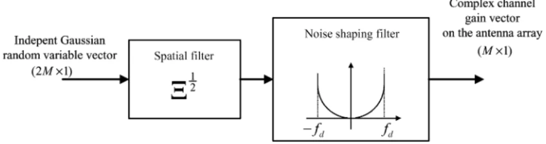
Fig. 6 shows the simplified block diagram of the spatially and temporally correlated channel model. Rayleigh-fading patterns can be produced by independently generated Gaussian random variables in both real and imaginary parts of an equivalent base-band signal. First, a linear transform, which models the spa-tial correlation of the complex received signals on the antenna
Fig. 7. Average bit-error probability versus relative thresholds with different DoA in a fixed two-path channel when7 = 5 dB.
array, is used to generate a vector of spatially correlated random variables [25]. After that, a noise-shaping filter is then used to produce the temporal correlation of the channel-fading process [26]. The output of the channel simulator is a vector of com-plex fading pattern on the antenna array. In order to simulate a frequency-selective fading channel, the fading pattern of each temporally resolvable path can be generated independently by using the previously described channel simulator.
The simulation scenario for the mobile radio channel case is described as follows. We assume that a vehicle moves around a circle with radius of 100 m at vehicle speeds of 8, 30, and 120 km/h (the Doppler frequency shift being 15, 55, and 222 Hz, respectively). To avoid the broading effect in DFT beam-forming [12], a cell is assumed to be divided into three 120 sectors. Therefore, we consider only the cases in which the main DoA swings between 60 and 60 . Two termporally resolv-able paths are assumed in the mobile radio channel model. Each path has the same swinging DoA, AoS, and Doppler frequency shift, but a different delay. Here, the excess delay of the second path was set to 3 s.
We that assumed each path has the same average SNR , where is the average energy per bit of the data signal for each path and is the variance of noise. Suppose that is the total number of temporally resolvable paths ( for both the static channel and the mobile channel), the total average SNR is . We did not include the pilot signal power in calculation because pilot power is much less than the interference noise level. The system performances were shown by plotting the average bit-error probability versus .
B. Simulation Results
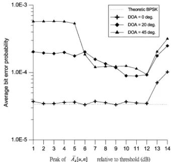
To suppress MAI, we select only several main signal paths and discarded all the other paths according to the processed 2-D (spatial and temporal) signals in the channel-sounding block. A threshold was chosen according to the peak value of the estimate of the channel-intensity profile . Figs. 7–9
Fig. 8. Average bit-error probability versus relative thresholds with different DoA in a fixed two-path channel when7 = 7 dB.
Fig. 9. Average bit-error probability versus relative thresholds with different DoA in a fixed two-path channel when7 = 9 dB.
show bit-error probabilities versus different threshold level se-lections in the static channel when is 5, 7, and 9 dB, respec-tively. Here, for estimating the channel-intensity profiles, we set and (i.e., the overall average window length is about 10 s). The time constant parameters of the IIR filter in the channel sounder was set to 0.9. We observe from these fig-ures that the performance in the case of approaches the theoretic BPSK performance, because the spatial FFT line spectrum at 0 points directly to the DoA of 0 . In the other two cases, no FFT line spectrum directly points to the DoAs of 20 and 45 ; therefore, performance degrades. In these two cases, most of the signal energy is dispersed into two neigh-boring FFT line spectra. Intuitively, we can choose a smaller threshold to include in more signal energy, but this might also include in more “unwanted” noise. Therefore, an appropriate threshold level should be chosen. All three figures show that a
Fig. 10. Average bit-error probability versus7 with different DoA in a fixed two-path channel( = 0:9).
Fig. 11. Average bit-error probability versus7 with different AoA 21 in a mobile two-path fading channel when the vehicle speed is 8 km/h(f = 15 Hz).
threshold level between 7 and 12 dB provides adequate perfor-mance.
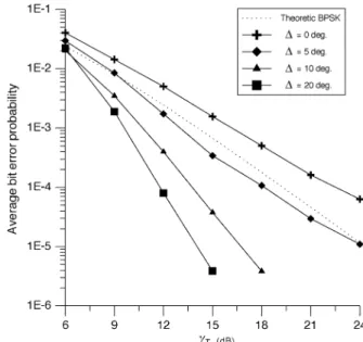
Fig. 10 shows the average bit-error probability versus in the static channel. Here, we set , , , and to be 7 dB below the peak value of in channel sounding. It is observed that in the case of , the re-ceiver achieves almost the same performance as the theoretic BPSK result; in the other two DoA cases, 1 dB of SNR degra-dation occurs at a BER of .
Finally, we simulated the 2-D RAKE receiver in the mobile radio channel. The simulated BER performances are presented in Figs. 11–13. To estimate the channel-intensity profile in the channel sounder, was set to 5 and was adapted to the channel-fading rate and set to 1080, 288, and 72 as the Doppler frequency shift was set to 15, 55, and 222 Hz, respectively
Fig. 12. Average bit-error probability versus7 with different AoA 21 in a mobile two-path fading channel when the vehicle speed is 30 km/h(f = 55 Hz).
Fig. 13. Average bit-error probability versus7 with different AoA 21 in a mobile two-path fading channel when the vehicle speed is 120 km/h(f = 222 Hz).
(i.e., the average window length corresponds to a time period in which a vehicle travels about five wavelengths in distance). Similarly, was set to 0.9, 0.8, and 0.7 in the three cases. The threshold for path selection was set to 7 dB below the peak value of in channel sounding. The theoretic BPSK re-sult shown here is the textbook rere-sult for coherent detection with a RAKE receiver in an equal-strength two-path Rayleigh-fading channel (i.e., the diversity order is 2) [22]. Comparing the theo-retic performance with our simulation result in the case, we found that there are 1.5-, 2-, and 6-dB SNR degradation as was set to 15, 55, and 222 Hz, respectively. As Doppler fre-quency shift increases, the performance degradation increases. This is because the delay involved in the IIR filtering induces more severe channel-estimation errors at a high vehicle speed.
The diversity gain in the case can be achieved only from the two temporally resolvable paths, i.e., the diversity order is 2. Nevertheless, as observed from Fig. 11-13, the receiver perfor-mance improves as increases. This performance improve-ment comes from the fact that this 2-D RAKE receiver now ben-efits not only from the temporal diversity gain, but also from the spatial diversity gain, as it can resolve more paths in two (spa-tial–temporal) dimensions.
V. DISCUSSION ANDCONCLUSION
In this paper, we described a 2-D RAKE receiver architecture that is based on FFT-matched filtering for CDMA uplink com-munications. This receiver architecture has the following fea-tures.
• This 2-D RAKE receiver is robust to the fast change in the channel because it adopts a matched filter architecture and all the signal processing is done on a symbol-by-symbol basis.
• Channel sounder explores both the spatial and temporal characteristics of the channel. Performance can be im-proved by taking the advantage of both spatial and tem-poral diversity gains.
Here, we calculate the computation complexity of the 2-D RAKE receiver. The first 2-D FFT needs
multiplications per symbol. Three banks of multipliers are needed for data-code despreading, channel matching, and pilot-code despreading. Each multiplier executes multiplications per symbol. Overall, the above three oper-ations need multiplications per symbol. A bank of M IFFT operations and a bank of M FFT operations are used for signal transformation in the channel sounder, i.e., the number of multiplications needed is per symbol. Overall, the total number of complex multiplications needed per symbol
is . According to the
system parameters used in our computer simulation (listed in Table II), the total number of multiplications needed is approximately 795 million instructions per second (MIPS).
In this paper, we simulated the 2-D RAKE receiver in both a static channel and a mobile radio channel. Our simulation results show that a threshold level should be appropriately chosen to select main signal paths and suppress interference in the channel sounder. Our simulation results show that average bit-error probability performance of the system is close to the theoretic result in a static channel. In the mobile radio channel, we found that the system performance degrades as the Doppler frequency increases. On the other hand, the performance im-proves as AoS parameter increases as the 2-D RAKE receiver can resolve more paths and acquire spatial diversity gain.
With this 2-D RAKE receiver architecture, we process the received signal with maximal ratio combining and treat all of the MAIs as white noise. To further improve the system per-formance, multiuser detection can be integrated with the 2-D RAKE receiver. With such an approach, we not only form a beam pattern to a desired user, but also in effect put a “null” to the directions of MAI. This joint receiver architecture will be equivalent to an optimum beamformer. Parallel interference cancellation (PIC) techniques can be easily integrated with the
2-D RAKE receiver architecture [27]. With a PIC detector in-cluded, we can estimate MAI first and then subtract the esti-mated MAI from the received signals. We expect that through this technique both system performance and system capacity can be further improved.
ACKNOWLEDGMENT
The authors would like to thank the anonymous reviewers for their comments to improve the correctness and presentation of this paper.
REFERENCES
[1] F. Adachi, M. Sawahashi, and H. Suda, “Wideband DS-CDMA for next-generation mobile communication systems,” IEEE Commun. Mag., vol. 36, pp. 56–69, Sept. 1998.
[2] E. Dahlman, P. Beming, J. Knutsson, F. Ovesjo, M. Persson, and C. Roobol, “WCDMA—the radio interface for future mobile multimedia communications,” IEEE Trans. Veh. Technol., vol. 47, pp. 1105–1118, Nov. 1998.
[3] G. K. Chan, “Effects of sectorization on the spectrum efficiency of cel-lular ratio systems,” IEEE Trans. Veh. Technol., vol. 41, pp. 217–225, Aug. 1992.
[4] J. C. Liberti Jr. and T. S. Rappaport, “Analytical results for capacity im-provements in CDMA,” IEEE Trans. Veh. Technol., vol. 43, pp. 680–690, Aug. 1994.
[5] , Smart Antennas for Wireless Communications. Englewood Cliffs, NJ: Prentice-Hall, 1999.
[6] G. L. Turin, “Introduction to spread-spectrum antimultipath techniques and their application to urban digital radio,” Proc. IEEE, vol. 68, pp. 328–353, Mar. 1980.
[7] B. H. Khalaj, A. Paulraj, and T. Kailath, “2D RAKE receivers for CDMA cellular systems,” in Proc. GLOBECOM’94, San Francisco, CA, Nov. 1994, pp. 400–404.
[8] J. S. Thompson, P. M. Grant, and B. Mulgrew, “Smart antenna arrays for CDMA Systems,” IEEE Pers. Commun. Mag., vol. 3, pp. 16–25, Oct. 1996.
[9] R. Kohnon, “Spatial and temporal communication theory using adaptive antenna array,” IEEE Pers. Commun. Mag., vol. 5, pp. 28–35, Feb. 1998. [10] T. F. Wong, T. M. Lok, J. S. Lehnert, and M. D. Zoltowski, “A linear receiver for direct-sequence spread-spectrum multiple-access systems with antenna arrays and blind adaption,” IEEE Trans. Inform. Theory, vol. 44, pp. 659–676, Mar. 1998.
[11] M. Nagatsuka and R. Kohno, “A spatially temporally optimal multi-user receiver using an array antenna for DS/CDMA,” IEICE Trans. Commun., vol. 43, pp. 1479–1489, Nov. 1995.
[12] A. F. Naguib and A. Paulraj, “Performance of wireless CDMA with M-ary orthogonal modulation and cell site aantenna arrays,” IEEE J. Se-lect. Areas Commun., vol. 14, pp. 1770–1783, Dec. 1996.
[13] M. Dell’Anna and A. H. Aghvami, “Performance of optimum and sub-optimum combining at the antenna array of a W-CDMA systems,” IEEE J. Select. Areas Commun., vol. 17, pp. 2123–2137, Dec. 1999. [14] A. F. Naguib, “Space-time receivers for CDMA multipath signals,” in
Proc. ICC’97, Montreal, PQ, Canada, Nov. 1997, pp. 304–308. [15] J. J. Blanz, A. Papathanassiou, M. Haardt, I. Furió, and P. W. Baier,
“Smart antenna for combined DOA and joint channel estimation in time-slotted CDMA mobile radio systems with joint detection,” IEEE Trans. Veh. Technol., vol. 49, pp. 293–306, Mar. 2000.
[16] A. F. Naguib, A. Paulraj, and T. Kailath, “Capacity improvement with basae-station antenna arrays in cellular CDMA,” IEEE Trans. Veh. Technol., vol. 43, pp. 691–698, Aug. 1994.
[17] L. C. Godara, “Application of antenna arrays to mobile communications. II. Beam-forming and direction-of-arrival considerations,” Proc. IEEE, vol. 85, pp. 1195–1245, Aug. 1997.
[18] M. B. Pursley, “Performance evaluation of phase-coded spread-spec-trum multiple-access communication—Part I,” IEEE Trans. Commun., vol. COM-25, pp. 795–799, Aug. 1977.
[19] R. Kohno, C. Yim, and H. Imai, “Array antenna beamforming based on estimation of arrival angles using DFT on spatial domain,” in Proc. PIMRC’97, London, U.K., Sept. 1991, pp. 38–43.
[20] S. Y. Wang and C. C. Huang, “On the architecture and performance of an FFT-based spread spectrum downlink RAKE receiver,” IEEE Trans. Veh. Technol., vol. 50, pp. 234–243, Jan. 2001.
1049–1057, Nov. 1994.
[26] W. C. Jakes Jr., Microwave Mobile Communications. New York: Wiley, 1974.
[27] S. Moshavi, “Multi-user detection for DS-CDMA communications,” IEEE Commun. Mag., vol. 34, pp. 124–136, Oct. 1996.
Shin-Yuan Wang was born in Hsinchu, Taiwan. He
received the B.S. degree in electrical engineering from Nation Taiwan Ocean University, Keelung, Taiwan, in 1993 and the M.S. and Ph.D. degrees in communication engineering from National Chiao Tung University (NCTU), Hsinchu, Taiwan, in 1995 and 2001, respectively.
Since 2001, he has been an Engineer in the Wireless Communication Technology Department, Computer and Communications Research Labo-ratories, Industrial Technology Research Institute, Hsinchu, Taiwan. He is currently involved in the baseband algorithm and architecture design on third-generation wireless communications. His current research interests include the design of baseband receiver architectures for spread-spectrum systems and smart-antenna systems.
NY, as a Research Staff Member, working on indoor radio-communication system design. Since 1992, he has been with the Department of Communication Engineering, National Chiao Tung University, Hsinchu, Taiwan, currently as a Professor.
Chat Chin Quek was born in Muar, Malaysia, in
1975. He received the B.S. degree in electrical en-gineering from National Taiwan University, Taiwan, in 1999 and the M.S. degree in communication engineering from National Chiao Tung University (NCTU), Hsinchu, Taiwan, in 2001.
From 2001 to 2003, he was a Research Engineer with NCTU Microelectronics and Information Sys-tems Research Center, investigating algorithms and very-large-scale integration (VLSI) architectures for communication. Since 2003, he has been with the Network and Communication Department, Realtek Semiconductor Corp., Hsinchu, Taiwan. His research interests include signal processing and VLSI design for communications.