Slow-Moving Objects Extraction via Adaptive
Frame Differencing for Video Surveillance
Chun-Ming Tsai
Department of Computer Science, Taipei Municipal University of Education
Zong-Mu Yeh
Department of Mechatronic Technology, National Taiwan Normal University
Abstract ― Conventional moving objects detection
methods are not efficient for real-time video surveillance. Furthermore, most of them do not produce effective ex-traction results for certain types of moving objects: slow, fast, far, and near. This paper presents a moving objects extraction algorithm to detect the abovementioned moving objects simultaneously. This method includes moving de-tection by adaptive frame differencing, binarization by automatic thresholding, bounding-boxes are obtained by connected component labeling, and localization the mov-ing objects by cascade framework. The adaptive frame differencing uses different inter-frame for frame differ-encing. The number of inter-frame depends on variations in the differencing image. The thresholding method uses a modified triangular algorithm and these variations to de-termine the threshold value and reduces most small noises. The localization cascade framework combines bound-ing-boxes-based morphological operations with associative rules. This framework merges broken objects and re-moves noise pertaining to small and spread connected components. The fps value (maximum 72) depends on the speed of the objects. The number of inter-frame is in-versely proportional to the speed. The results demonstrate that our system is more efficient than traditional moving objects methods. The true and false positive rates are 97.58% and 0.438%, respectively.
Index Terms ―Adaptive frame differencing, Video
sur-veillance, Slow-moving objects, Bounding-boxes-based morphological operations, Associative rules.
I. INTRODUCTION
Moving objects detection is the fundamental step in a visual surveillance system, as well as in a vari-ety of applications of computer vision, including intelligent traffic systems, intelligent parking lots, intelligent healthcare systems, intelligent home-care systems, and intelligent homeland. This method can be divided into four main types [1]:
background subtraction [2] [3], optical flow [4]-[6], frame differencing [7] [8] and hybrid methods [9] [10]. The background subtraction method detects motion objects as the difference between the cur-rent frame and an image of the background model. However, there are many problems encountered in the background subtraction method: (1) automatic building of the background model image; (2) up-dating the background model; and (3) deciding the update rate. Thus, numerous researchers have pro-posed many methods to solve the abovementioned problems [11]-[13] [17]. The optical flow method uses the motion of the moving objects to entail in-tensity changes in the magnitude, which become important cues for locating the object in time and space. However, their relationship is not unique due to the presence of noise or other external causes like illumination drifts. Furthermore, these algo-rithms are not computationally efficient [13]. The frame differencing method is based on the differ-ence between two or three consecutive frames. This is the simplest method for extracting moving ob-jects and can adapt to dynamic environments. However, this method cannot detect the entire shape of the motion object [10]. This method hold good only for specific speeds of the motion object. Furthermore, it is very sensitive to the threshold value used to convert the differencing image to a binarization image. Several hybrid methods that combine the abovementioned methods have been developed to detect the regions of change. However, none of these methods can solve the abovemen-tioned problems of background subtraction and op-tical flow.
frame differencing is the simplest method for
ex-tracting moving objects. Herein, we will solve the problems encountered in traditional frame differ-encing. These problems include (1) the reason for using two-frame or three-frame differencing; (2) obtaining a robust difference threshold value; (3) extraction of the entire moving object; and (4) de-veloping a method for processing the moving ob-jects that move slowly and quickly. In this paper, an efficient and effective moving object extraction method is proposed to solve the four abovemen-tioned problems. Figure 1 shows the flow diagram of the proposed system. This flow diagram includes adaptive frame differencing (AFD), automatic thresholding (AT), connected component labeling (CCL), and cascade moving objects localization.
The rest of this paper is organized as follows. Section II briefly discusses the adaptive frame dif-ferencing. Section III presents the automatic thresholding. Cascade moving objects localization is described in Section IV. Section V provides the results of the experiments on the proposed system. Finally, the conclusions and future works are de-scribed in Section VI.
II. ADAPTIVE FRAME DIFFERENCING The variations in the image produced by two-frame differencing image from the surveillance video in an inn are observed. The video includes 1400 frames. The two-frame differencing method is used to obtain the differencing image. Subsequently, the variance for each differencing image is com-puted. Figure 2 shows the results for the variations in 1400 differencing images. The horizontal axis
represents the number of the two-frame differenc-ing image. The vertical axis represents the variance for each differencing image. From Fig. 2, it is ob-served that many of the variances are zero. For example, ten variances between 0 and 200 differ-encing images are zero. Some variances between the 1200th and the 1400th differencing images are very significant. Some variances between 0 and 71 differencing images are moderate. Apparently, there are many variances that are insignificant. For ex-ample, the variances between the 72nd and 647th differencing images are small (below 10.0). Based on the above observations, the representation for these various variances and the method of process-ing these video frames are described.
First, if the variances of the differencing images are very small, it implies that the two successive frames are similar. Thus, for this case, the current frame need not processed. Instead the next frame is tested. Secondly, if the variances of the differencing images are large or moderate, the change between the two successive frames is significant, the speed of the motion objects is high, or the distance be-tween the motion objects and the video camera is very less. In these cases, the changes can be easily detected by the conventional two-frame or three-frame differencing method. Finally, if the variances of the differencing images are insignifi-cant, it implies that the speed of the motion objects is less. Moreover, if the distance between the mo-tion objects and the video camera is more, the Fig. 2. Variations in the image formed by two-frame dif-ferencing.
Videos
Adaptive frame differencing Automatic thresholding
Extracted moving objects Cascade moving objects localization
Connected component labeling
variances of the differencing images are
insignifi-cant. Under these conditions, the following con-ventional procedures (removal of noise, morpho-logical operations, and CCL operations) cannot de-tect the motion objects properly. Moreover, the time complexity of three-frame differencing is thrice that of two-frame differencing. The space complexity of three-frame differencing is twice that of two-frame differencing. Thus, two-frame differ-encing is faster than three-frame differdiffer-encing. However, its accuracy of the detection is less than that of three-frame differencing.
Hence, in this paper, a general frame differenc-ing algorithm is proposed to detect the motion ob-jects. This idea is based on the variation in the dif-ferencing image. If the motion object is fast-moving or of the distance between the motion objects and the video camera is short, the variation in the difference image is large. On the contrary, if the motion object is slow-moving or if the distance between the motion objects and the video camera is more, the variation in the difference image is small. The main formula of our proposed adaptive frame differencing technique is . ) , ( ) , ( i n i i i F x y F x y T D = − − > (1)
Here, Di is the difference image; i, the current frame image of the input video; n, the number of the frame next to the current frame image, and Ti, a variable difference threshold value, which will be described in Section III. The algorithm of the pro-posed adaptive frame differencing is described as follows.
1) Set the initial the interval frame number (n) as 1.
2) Are the ith frame image and the (i-n)th frame image similar? If the difference mean between the ith frame and the (i-n)th frame is smaller than a pre-learning parameter, these two images are simi-lar.
3) If step (2) is true, go to the next frame, and con-tinue step (2).
4) Use equation (1) to obtain difference image, Di. 5) Is the variation in Di sufficient? If the variation is larger than a pre-learning parameter, the varia-tion is sufficient.
6) If step (5) is false, next frame and increase the interval frame number; and then continue step (2).
7) If step (5) is true, continue automatic thresh-olding method.
From the above algorithm, it is apparent that step 2 is used to detect whether the two successive frames are similar or not. If the two successive frames are similar, processing is not required. This testing can reduce the entire process time. Step 5 is used to detect whether the variation in the differ-encing image is sufficient or not. If the variation in the differencing image is significant, it implies that the motion objects is moving fast or its distance from the video camera is short. In these cases, the number of the interval frame is 1. If the variation in the differencing image is insignificant, it reflects that the motion object is moving slowly or its dis-tance from the video camera is more. In these cases, the number of the interval frame is increased. Sub-sequently, we proceed to the Step 2 and repeat the abovementioned steps. The number of the interval frame is different. To process lesser variations in the differencing image, a greater number of frames in the given interval will be required. Thus, this proposed method is named as adaptive frame dif-ferencing algorithm.
III. AUTOMATIC THRESHOLDING METHOD Thresholding is very important for binarization. In order to segment moving objects, the differenc-ing image needs to be converted into a binary im-age. Subsequently, connected component labeling is used to segment the moving objects. However, if the threshold value is too small, much noise is produced in the binary image. In this case, the conventional motion extraction method uses binary morphological operations to remove the noise. Sometimes, due to an improper threshold value, the connected component objects cannot be extracted properly by removing the noise. Moreover, if the threshold value is too large, many broken objects are produced in the binary image. Thus, obtaining an adequate threshold value for the differencing image is very important.
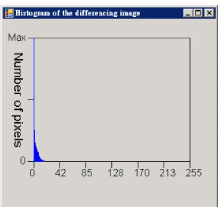
The histogram of the differencing image (Fig. 3) is observed. The horizontal axis is the gray level of the differencing image. The vertical axis is the number of pixels with one gray level in the differ-encing image. If two frames are similar, the
tion in the differencing image is located at a low
gray level. If two frames are dissimilar, the varia-tion is located at a high gray level. Moreover, there is usually one large peak at the low gray level. This represents that most of the two images are station-ary. Greater the change made, higher is the gray level in the differencing image. The differencing images usually do not have two normal distribu-tions. Thus, it is improper to classify this differ-encing image into two classes by the Otsu thresh-olding method [14]. Herein, the modified triangle thresholding method [15] is employed to threshold the differencing image into a binary image. The modified triangle thresholding method is described in the subsequent section.
From aforementioned, if threshold value is too small, much noise is produced. In the conventional frame differencing method, binary morphological operations are used to remove the noise. However, these operations repeatedly process the entire im-age. Furthermore, if the threshold value is too large, many extraction motion objects get broken. Never-theless, little noise is produced. Hence, the auto-matic thresholding method is based on this idea. A larger threshold value is obtained to reduce the noise. By using this large threshold value, the bi-nary result produces little noise. Therefore, in the following procedure, connected component label-ing is used directly to extract the motion objects. The binary morphological (BM) operations are not to be used before implementing the connected component labeling. Notably, this procedure speeds up the entire process. However, the extracted mo-tion objects are broken. This problem will be solved by using bounding-boxes-based morpho-logical (BBM) operations to merge the broken
ob-jects. These BBM operations can be found in [16]. The proposed automatic thresholding algorithm is described below.
1) Obtain the histogram of the differencing image (which is obtained by the adaptive frame differ-encing method described in Section II)
2) Use a Gaussian smoothing filter [15] to smooth the original histogram to remove noise.
3) Use the modified triangular thresholding method [15] to obtain the threshold value Dthr.
4) Obtain the automatic threshold value Ti by the equation . σ × + = D k Ti thr (2)
Here, k is a noise removal constant, which is used to adjust the threshold value to obtain a binary im-age with less noise (herein, k = 2.0 in pre-learning). σ is the standard deviation of the differencing im-age and depend on the surveillance environment. 5) Use Ti to convert the differencing image to the binary image.
From the above algorithm, when the variation between two frames is large, the variance of the differencing image is also large. Thus, the auto-matic threshold value is adjusted to a higher limit to remove more noise and reserve the motion ob-jects. If the difference between two frames is small, the variance of the differencing image is also small. Hence, the automatic threshold value is adjusted to a lower limit to convert the differencing image into a binary image.
IV. CASCADE MOVING OBJECTS LOCALIZA-TION
After the automatic thresholding and connected component labeling, many moving objects have been extracted. These objects may be humans, cars, or noise. Herein, a cascade localization method for moving objects is proposed to remove small and spread noise CCs, to merge concentrated broken CCs, and to locate moving objects. The localization method includes the features employed, associative rules, and cascade localization framework. These steps will be described as follows.
A. Features employed
To obtain the true moving objects, the results obtained after the connected component labeling Fig. 3. Histogram of the differencing image.
are observed. It is found that the slow-moving
mo-tion objects shows by the broken CCs and these CCs gather close to each other. The noise is small and spread. Thus, six features are defined to be used in the associative rule to remove the noise and merge the broken objects.
1) The luminance mean, U, of a frame image: This feature describes whether the luminance of a frame image is small or large. If the luminance mean is small, the luminance in a frame image is almost dark. If the luminance mean is large, the luminance in a frame image is almost bright.
2) The luminance mean, u, of a CC: This feature describes whether the luminance of a CC is small or large. If the luminance mean is small, the lumi-nance in a CC is almost dark. If the lumilumi-nance mean is large, the luminance in a CC is almost bright.
3) The distance, D, between two BBs: This feature describes whether the distance between any two BBs is small or large. When the distribution of some BBs is concentrated, their distance between them is small. On the contrary, when the distribu-tion of some BBs is spread, the distance between them is large.
4) The area, A, of the bounding box of the CC: This feature describes whether the area of the bounding box of the CC is small or large.
5) The moving pixels ratio, MPR, of a BB: This feature describes whether the number of the mov-ing pixels in a BB is small or large. The movmov-ing pixels, N, is the number of binarization pixels in a given CC. The binarization pixels are obtained by the adaptive frame differencing and automatic thresholding methods. The moving pixels ratio is the ratio of a BB’s moving pixels to the image area. 6) The aspect ratio, AR, of a BB: This feature de-scribes whether the ratio of a BB’s width to its height is small or large. In other word, this feature is used to represent which the BB is human or non-human shape.
B. Associative rules
Small CCs cause random noise or broken parts of the moving object. The random noise is pro-duced by the wind, sunlight, and shadows. For example, the original surveillance location is
illu-minated by the sun. The trees swaying in the wind produce shadows, owing to which the illumination changes from bright to dark. This change gives rise to random noise. Broken motion objects are caused by the human who walks at a slow pace or swing their arms as they walks. Since slow-moving body parts are not easy to detect, broken motion objects are produced. Herein, six associative rules are de-fined to remove the random noise and merge the broken objects. These six rules use the six features and BBM operations to remove or merge the small BBs.
1) Removing light shadow CCs: The characteristic feature of light shadows is thatthe variation in their luminance mean u between the previous image and the current frame image is large. Thus, u is used to remove noise produced by these light shadows. This rule is defined as follows: If the luminance means (U) of previous frame and the current frame are similar, the difference in luminance mean be-tween the previous and current frames in a CC is greater than a predefined value (Tu), BB-based ero-sion is used to remove this CC. Tu is set to 50 which is obtained from learning.
2) Merging concentrated CCs: The broken objects are concentrated to form a complete object. If some CCs are centralized, the distance feature is used to merge the concentrated CCs into a large CC. This rule is defined as follows: If the distance between two CCs is smaller than a predefined value (TD1), BB-based closing is used to merge them. TD1 is set to 0.0125 * min (W, H) which is obtained from learning. W and H are the width and height of the video frame, respectively.
3) Removing spread and small CCs: Many small CCs remain after the first applying the two rules (removing light shadows and merging concentrated CCs). These small CCs generate random noise. They are characterized by a smaller area and are scattered. The noise is eliminated by applying the area and distance features. This rule is defined in the following manner: If the area of CC is smaller than a predefined value (TA1) and the distance be-tween this CC and another CC is greater than a predefined value (TD2), BB-based opening is used to remove it. TA1 and TD2 are set to 0.00004 * W* H and 0.1 * min (W, H), respectively, which are ob-tained from learning.
4) Merging small and concentrated CCs: Small
and concentrated CCs are produced by a motion object whose motion is insignificant. In particular, a CCD camera can monitor many people, some of whom perform insignificant motions, while others perform motion significant motions. Thus, the sig-nificant motion is more prominent. The insignifi-cant motion produces broken CCs after the thresh-old result. To merge such broken CCs, the area and distance features are used. This rule is defined as follows: If the area of a CC is smaller than a prede-fined value (TA2) and the distance between this CC and another CC is smaller than a predefined value (TD3), BB-based closing process is used to merge them. TA2 and TD3 are set to 0.00125 * W* H and 0.1 * min (W, H), respectively, which are obtained from learning.
5) Removing erroneously merged CCs: This rule is used to remove CCs that contain small motion pixels. Erroneously merged CCs are produced by the abovementioned merging rule. The motion pixel ratio is used to remove the erroneously merged noise CCs. This rule is defined as follows: If a CC’s motion pixel ratio is smaller than a prede-fined value (TMPR), BB-based erosion is used to remove it. TMPR is set to 0.000027 which is ob-tained from learning.
6) Merging closed small CCs: This rule is used to merge the images with non-human shapes and closed small CCs. After applying the five above-mentioned rules, CCs with non-human shape CCs are produced. In particular, when a human moves slowly, the movements of limbs are significant. However, the movements performed by the rest of his body are insignificant. Thus, a broken body image of the body is produced. The aspect ratio and distance features are used to merge the broken im-age of the body. This rule is defined as follows: If the distance between two CC is smaller than a pre-defined value (TD4) and their aspect ratios do not conform to the ratio of the human shape, CC-based closing is used to merge them. TD4 is set to 0.03 *
H which is obtained from learning. C. Cascade localization framework
Many CCs have been extracted after motion de-tection by adaptive frame differencing, binarization by automatic thresholding, and extraction of mo-tion CCs by connected component labeling. These
CCs may be humans, cars, or noise. Herein, a cas-cade localization framework is proposed to remove and merge small CCs and to obtain the true moving objects (humans or cars). This procedure is based on the BBM operations [16] and associative rules.
The area and distance features are used to decide whether the subsequent rule is executed or not. In the first rule, light shadow CCs are eroded by BB-based erosion. In the second rule, if the re-maining CCs are small and concentrated, they are merged into complete-motion CCs by BB-based closing. After the application of the first two rules, many small and spread noise CCs would still re-main. In the third rule, these spread and small CCs are removed by BB-based opening. Many small and concentrated broken CCs would still exist. Thus, the fourth rule is applied to merge them into a complete large CC. After applying this rule, a few CCs are produced erroneously, which are removed by applying the fifth rule. Final, the CCs with non-human shapes or closed CCs are merged by using the sixth rule into form a complete CC with a human shape or a large CC.
Figure 4 shows an example of adaptive frame dif-ferencing, automatic thresholding, and connected com-ponent labeling. Figures 4(a)-(b) are the 241st and 252nd frames in the source video clip. As observed from these figures, three peoples are involved in a discussion in the surveillance inn. Since their mo-tions are insignificant, the two-frame and
(a) (b)
(c) (d)
Fig. 4. Examples of adaptive frame differencing, automatic thresholding, and connected component labeling. (a) #241; (b) #252; (c) binary image; (d) connected components.
three-frame differencing methods cannot detect
their motions. The proposed adaptive frame differ-encing method can detect their motions by using eleven inter-frames. The differencing image is converted into a binary image (Fig. 4(c)) by using the automatic thresholding method. The moving objects (Fig. 4(d)) are segmented by connected component labeling. Notably, the conventional methods of moving object detection use BM opera-tions to remove noise at this stage. This stage is skipped in the proposed method. If the BM opera-tions are used in this stage, slow-moving objects cannot be detected. From Fig. 4(d), it is apparent that some of the remaining CCs are caused by in-creasing the inter-frames. The noise increases with the inter-frames. The noise is produced by light shadows, rustling of leaves shaking, and floating air. However, increasing the inter-frames can detect the slow-moving objects and distant objects.
From above reasons, the cascade localization procedure is used to locate truly moving objects.
The results obtained by using the first rule (remov-ing light shadow CCs) are shown in Fig. 5(a). The light shadow CCs on the railing have been removed. After applying the second rule (merging concen-trated CCs), the concenconcen-trated CCs are merged into a single large CC (Fig 5(b)). This large CC includes the images of two complete persons and one half of the image of a third person. Many small and spread CCs still exist in this figure, which are eliminated by using the third rule (removing spread and small CCs) (Fig. 5(c)). Figure 5(d) shows the result ob-tained by using the fourth rule. The CC at the top-left is a CC with noise. Its motion pixels are very small. Thus, after applying the fifth rule, the erroneously merged CC is removed (Fig. 5(e)). Fi-nally, the small CC is merged with a large neighboring CC to obtain a single large CC. This large CC contains the complete images of three persons (Fig. 5(f)).
V. EXPERIMENTAL RESULTS AND DISCUS-SION
The abovementioned methods are implemented by using Visual C# 2008, operating on a 3.4 GHz Pentium 4 CPU. The video clips tested in our ex-periments were recorded at Town and Country Inn in Santa Barbara, CA, USA on 02/20/2006. The web camera used for this purpose is a Logitech QuickCam. The resolution of each video frame is 320 × 240 pixels, and the frame rate is 30 fps. The video clips include moving humans, light shadows caused by the sun, leaves rustling in the wind, and changing illuminations.
In our experiments, the motion object extraction results and performance analysis of the execution times are compared for three types frame differ-encing methods: two-frame differdiffer-encing (2FD), three-frame differencing (3FD), and adaptive frame differencing (AFD). Furthermore, two background subtraction methods: Mixture of Gaussians (MoG) [2] and MoG with adaptive number of Gaussians (AMoG) [17] are used to compare the result. The comparisons are described as follows.
For the video clips of slow-moving objects, the extraction results of the AFD, 2FD, and 3FD methods are shown in Table 1. In this video clip, three persons are involved in a conversation at the
(a) (b)
(c) (d)
(e) (f)
Fig. 5. Examples of the cascade localization procedures. (a Removing light shadow CCs; (b) merging concentrated CCs; (c) removing spread and small CCs; (d) merging small and concentrated CCs; (e) removing erroneously merged CCs; (f) merging closed small CCs.
surveillance location. Their motions are
insignifi-cant (932 frames). Hence, 2FD and 3FD fail to de-tect their motions. Furthermore, the video clip has 52 identical frames, in which the mean and vari-ance of the current and previous frames are equal. In this case, motion detection would be meaning-less. The conventional differencing methods are time-consuming in this case and cannot detect the motion objects. In other words, their false negative rates are high. The false negative rate of the pro-posed method is caused by an object that is almost stationary. From Table 1, it is evident that the pro-posed method is superior to conventional frame differencing methods.
The performance time analyses of AFD, 2FD, 3FD, and AMoG are shown in Table 2. This com-parison used the inn video clip (1334 frames) to be tested samples. The sizes of the motion object are from 26 × 60 to 188 × 239 pixels. The maximum size is produced by the shortest distance between the motion object and the CCD camera. To process this video clip, the execution times for AFD, 2FD, 3FD, AMoG are 18.457, 31.162, 40.874, and 115.149 seconds, respectively. The average frames per second (FPS) for AFD, 2FD, and 3FD are 72.27, 42.81, 32.64, and 11.58, respectively. The proposed method skips similar frames. Moreover, when the variance of the differencing image is small, the in-ter-frame is increased. Thus, the proposed method is the fastest. From Table 2, the proposed adaptive frame differencing method is found to be superior
to the traditional frame differencing and AMoG methods.
For the objective evaluation, the first data set of the 2006 IPPR contest (http://140.109.20.238/) was adopted. This data set involves indoor surveillance. There are 456 motion objects in total. The size of these objects range from 4 × 8 to 75 × 147 pixels. When the distance between the motion object and the CCD camera is long, the object size is small. On the contrary, the when the distance is short, the size of the object is large. In the first data set, the objects move at different speeds. Some of the ob-jects perform walking motion, some perform run-ning, and others walk and remain stationary, alter-nately. The data set provides manually extracted ground truth data. Table 3 shows the extraction sults obtained by using AFD, 2FD, and 3FD, re-spectively. From this table, the proposed AFD method is found to be superior to the 2FD method at a low false positive rate. Furthermore, the AFD method is superior to 3FD method at low false positive rates and high true positive rates. Table 4 shows the execution times obtained by using AFD, 2FD, 3FD, and AMoG for the 2006 IPPR’s first data set. From this table, the execution times for the AFD and 2FD methods are observed to be similar. Both these methods process the salient motion ob-ject faster than 3FD and AMoG methods.
In addition to the above performance analyses, Table 4
Comparison of time performance obtained by using AFD, 2FD and 3FD for 2006IPPR contest’s first data set (320 ×
240)
Methods Execution Times for 300
frames video clip FPS
AFD 6.592 (s) 69.17
2FD 7.247 (s) 62.92
3FD 9.257 (s) 49.26
AMoG 29.048(s) 10.33
Table 1
Comparison of extraction results obtained by using AFD, 2FD and 3FD for slow-moving video clips (320 × 240) Methods Total Objects True Positive Rate False Negative Rate False Positive Rate AFD 3862 96% 4% 1% 2FD 3862 73% 27% 3.4% 3FD 3862 65% 35% 2% Table 2
Comparison of time performance obtained by using AFD, 2FD and 3FD for slow-moving video clips (320 × 240)
Methods Execution Times for 1334
frames video clip FPS
AFD 18.457 (s) 72.27
2FD 31.162 (s) 42.81
3FD 40.874 (s) 32.64
AMoG 115.1489 (s) 11.58
Table 3
Comparison of extraction results obtained by using AFD, 2FD and 3FD for 2006IPPR contest’s first data set (320 ×
240) Methods Total Objects True Positive Rate False Negative Rate False Positive Rate AFD 456 97.58% 2.42% 0.438% 2FD 456 97.15% 2.85% 4.605% 3FD 456 92.98% 7.02% 5.92%
some experiments (involving fast-moving and
slow-moving objects, far objects, near objects, ob-jects performing significant and insignificant mo-tions, and checking whether binary morphology is used or not) are discussed for AFD, 2FD, and 3FD. These methods are combined with automatic
thresholding (AT) and our moving objects localiza-tion (MOL) method to extract the moving object. Besides, 2FD and 3FD are combined with fixed thresholding (FT), binary morphology (BM), and our moving objects localization (MOL) method to compare the moving object extraction perform-ances.
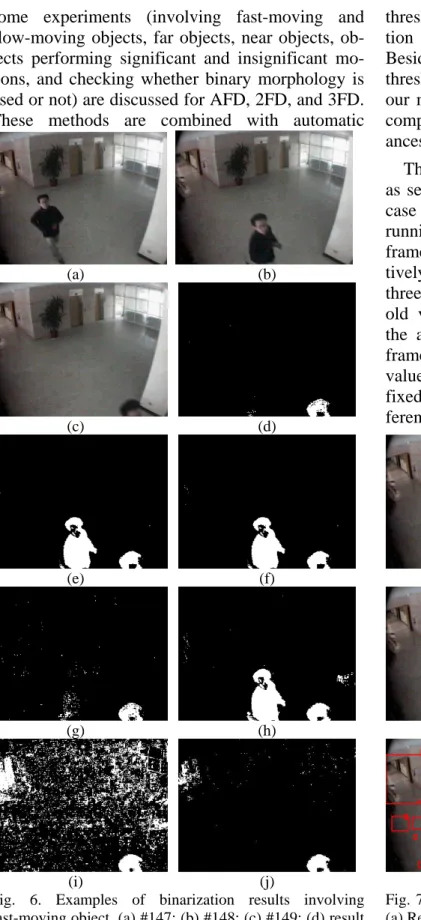
The motions of fast-moving objects are salient, as seen from their video clips. An example of this case is shown in Fig. 6, where the motion object is running. The original 147th, 148th, and 149th frame images are shown in Figs. 6(a)–(c), respec-tively. The binarization results obtained by using three-frame differencing with the automatic thresh-old value (3FDAT), two-frame differencing with the automatic threshold value (2FDAT), adaptive frame differencing with the automatic threshold value (AFDAT), three-frame differencing with a fixed threshold value (3FDFT), and two-frame dif-ferencing with a fixed threshold value (2FDFT) are
(a) (b) (c) (d) (e) (f) (g) (h) (i) (j)
Fig. 6. Examples of binarization results involving fast-moving object. (a) #147; (b) #148; (c) #149; (d) result obtained by 3FDAT; (e) result obtained by 2FDAT; (f) result obtained by AFDAT; (g) result obtained by 3FDFT; (h) result obtained by 2FDFT; (i) result ob-tained by MoG [2] at frame 148; (j) result obob-tained by AMoG [17] at frame 148. (a) (b) (c) (d) (e) (f)
Fig. 7. Examples for localization results following Fig. 6. (a) Result obtained by 3FDAT + MOI; (b) result obtained by 2FDAT or AFDAT + MOI; (c) result obtained by 3FDFT + BM + MOI; (d) result obtained by 2FDFT + BM + MOI; (e) result obtained by MoG + noise removal (NR) + BM + area filter (AF); (f) result obtained by AMoG + NR + BM + AF.
shown in Figs. 6(d)–(h), respectively. From this
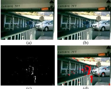
figure, noise produced by the 3FDFT method is the maximum (Fig. 6(g)). If the proposed AT method is used, the noise is suppressed to a maximum possi-ble extent (Fig. 6(d)). The 2FDAT, AFDAT, and 2FDFT methods produce “ghost” objects in the current frame (#149). These ghost objects will be removed by the motion object identification method. Overall, the best performance for binariza-tion is the delivered by the 2FDAT and AFDAT methods. In other words, the proposed AT method is effective in suppressing noise. The results by background subtraction: MoG and AMoG are shown in Fig. 6(i)-(j). These results contain more noises than the proposed method.
Figure 7 shows the localization results for Fig. 6 obtained by employing different methods. The re-sult obtained by the 3FDAT + MOL method is shown in Fig. 7(a). A small “ghost” object is pro-duced in this case. The localization result obtained by the 2FDAT + MOL method is similar to that ob-tained by the AFDAT + MOL (Fig. 7(b)) method. In this case, it can be seen that the “ghost” object has been eliminated. Figure 7(c) shows the result obtained by using the 3FDFT method combined with the BM and MOL methods. The BM removes the spread and small noise. However, the “ghost” object still exists. The identification result obtained by the 2FDFT method combined with the BM and MOL methods is shown in Fig. 7(d). The “ghost” object is produced on the right-hand side. Figures 7(e) and (d) are the results by background subtrac-tion: MoG and AMoG following post-processing: noise removal (NR), BM, and area filter (AF). From Figure 7, it is seen that the proposed moving objects localization method can remove the “ghost” object and spread and small noise. However, this method cannot remove the concentrated noise. Nevertheless, the proposed MOL method can merge the concentrated broken CCs caused by the slow-moving object (our subsequent experiment will show this process). Overall, the best localiza-tion result is obtained by combining the 2FDAT and AFDAT methods with the MOL method (Fig. 7(b)).
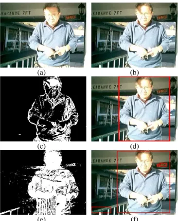
In the video clip showing slow-moving objects, we can see that their motions are insignificant. An example for this case is shown in Fig. 8. There are
two men and a one woman involved in a discussion. Their actions are not obvious. The conventional differencing (2FD and 3FD) and background sub-traction (AMoG) methods cannot detect these slow-moving objects. The proposed AFD method can detect these slow-moving objects by using 49 frames. Figures 8(a)–(d) indicate the original frames (#526 and #575), the binarization result ob-tained by the proposed AT method, and the local-ization result obtained by the proposed MOL method, respectively. Since the subjects are sta-tionary, the proposed method only detects the upper half of their bodies. Figures 8(e)-(f) are the binari-zarion result obtained by AMoG and the localiza-tion result obtained by post-processing: NR, BM, and AF on frame 575.
In the video clip showing large moving objects, it is seen that their motions are significant. An ex-ample of this case is shown in Fig. 9. The motion object is moving toward the CCD camera. The size of this large object is 188 × 239 pixels. All the frame differencing (AFD, 2FD, and 3FD) and
(a) (b)
(c) (d)
(e) (f)
Fig. 8. Example of slow-moving objects. (a) #526; (b) #575; (c) binarization result obtained by AT; (d) localiza-tion result obtained by MOL; (e) binarizalocaliza-tion result tained by AMoG on frame 575; (f) localization result ob-tained by post-processing: NR, BM, and AF on frame 575.
background subtraction (AMoG) methods can
tect this large object. However, for the motion de-tection, the computing time involved in the three-frame differencing method is more than that in the other methods. Figures 9(e)-(f) are the bi-narizarion result obtained by AMoG and the local-ization result obtained by post-processing: NR, BM, and AF on frame 1336. However, two noise bound-ing boxes are produced.
The motion of a small moving object in a video clip is not apparent. An example of this case is shown in Fig. 10. The motion object is moving to-ward the top-left corner. The size of this small ob-ject is 4 × 8 pixels. The AFD and 2FD methods can detect this small object. The 3FD method cannot detect this small object. Figures 10(e)-(f) are the binarizarion result obtained by AMoG and the lo-calization result obtained by post-processing: NR, BM, and AF on frame 2. However, the small moving object is too small to be noise which is removed by
the post-processing.
From the above comparisons, it can be seen that the proposed method can extract the motion objects that move quickly and slowly or those far and near the CCD camera. More detailed results of the video clips can be
viewed at
http://cmtsai.tmue.edu.tw/~cmtsai/MOE/NCS2009.htm. VII. CONCLUSIONS AND FUTURE WORKS
In this study, an efficient and effective moving objects extraction method is proposed. This method includes a novel adaptive frame differencing, automatic thresholding, and cascade localization methods. A video clip showing slow-moving ob-jects can be detected by adaptive adjusting the number of the inter-frames. Furthermore, the pro-posed frame differencing method can skip the similar frames to speed up the process time. The proposed thresholding method can determine the threshold value automatically. This threshold value can suppress the noise to reduce the process cost.
(a) (b) (c) (d) (e) (f)
Fig. 9. Example of a large moving object. The object is close to the CCD camera. (a) #1335; (b) #1336; (c) binari-zation result obtained by AT; (d) localization result obtained by MOL; (e) binarization result obtained by AMoG on frame 1336; (f) localization result obtained by post-processing: NR, BM, and AF on frame 1336.
(a) (b)
(c) (d)
(e) (f)
Fig. 10. Example of a small moving object. The object is far. (a) #1; (b) #2; (c) binarization result obtained by AT;
(d) localization result obtained by MOL; (e) binari-zation result obtained by AMoG on frame 2; (f) localiza-tion result obtained by post-processing: NR, BM, and AF on frame 2.
The localization method for moving objects is
based on associative rules and BB-based morpho-logical operations to remove noise pertaining to spread CCs, to merge small and concentrated CCs, and to locate the moving objects. The experimental results depict that the proposed method is computa-tionally more efficient and effective than the tradi-tional frame differencing and background subtrac-tion methods.
To obtain optimal extraction results and process-ing speed for extractprocess-ing motion objects in real ap-plication, our future studies will focus on the fol-lowing: (1) optimization of our program; (2) exten-sion of the proposed method to real applications.
ACKNOWLEDEMENTS
This work was supported by the Ministry of
Eco-nomic, R.O.C., under Grants MOEA-96-EC-17-A-02-S1-032 and National Science
Council, R.O.C., under Grants NSC 96-2221-E-133-001-.
REFERENCE
[1] R. Radke, S. Andra, O. Al-Kofahi, and B. Roysam, “Image Change Detection Algorithms: A System-atic Survey,” IEEE Trans. on Image Processing, vol. 14, no. 3, pp. 294-307, March 2005.
[2] C. Stauffer and W. E. L. Grimson, “Adaptive back-ground mixture models for real-time tracking, in
Proceedings of IEEE Computer Society Conference on Computer Vision and Pattern Recognition, vol.
2, pp. 246–252, 1999.
[3] M. Piccardi, “Background Subtraction Techniques: A Review,” IEEE Proc. SMC, vol. 4, pp.3099–3104, 2004.
[4] B. Galvin, B. McCane, K. Novins, D. Mason, and S. Mills, “Recovering Motion Fields: An Evaluation of Eight Optical Flow Algorithms,” In Proc. Of the
9th British Machine Vision Conference (BMVC’98),
vol. 1, pp. 195-204, 1998.
[5] L. Wixson, “Detecting Salient Motion by Accumu-lating Directionally Flow,” IEEE Transactions on
Pattern Analysis and Machine Intelligence, vol. 22,
no. 8, pp. 774-780, Aug. 2000.
[6] S. A. Velastin, BA Boghossian, B Lo, J. Sun, MA Vicencio-Silva, “PRISMATICA: Toward Ambient Intelligence in Public Transport Environments,” in
IEEE Transactions on Systems, Man, and Cyber-netics - Part A', vol. 35, no. 1, pp. 164-182, Jan.
2005.
[7] C. Anderson, P. Burt, and G. van der Wal, “Change detection and tracking using pyramid transforma-tion techniques,” In Proc. of SPIE - Intelligent
Ro-bots and Computer Vision, vol. 579, pp. 72–78,
1985.
[8] C. Kim, J. Hwang, “Fast and Automatic Video Ob-ject Segmentation and Tracking for Content-Based Applications,” IEEE Trans. on Circuits and
Sys-tems for Video Technology, vol. 12, no. 2, pp.
122-129, Feb. 2002.
[9] R. Collins, A. Lipton, T. Kanade, H. Fujiyoshi, D. Duggins, Y. Tsin, D. Tolliver, N. Enomoto, O. Ha-segawa, P. Burt, and L. Wixson, “A System for Video Surveillance and Monitoring: VSAM Final Report,” Technical report CMU-RI-TR-00-12, Ro-botics Institute, Carnegie Mellon University, May 2000.
[10] Y. L. Tian and A. Hampapur, “Robust Salient Mo-tion DetecMo-tion with Complex Background for Real-time Video Surveillance,” In Proc. of IEEE
Computer Society Workshop on Motion and Video Computing, vol. 2, pp. 30-35, 2005.
[11] D. S. Lee, “Effective Gaussian mixture learning for video background subtraction,” IEEE Trans.
Pat-tern Analysis and Machine Intelligence, vol. 27, no.
5, pp. 827–832, May 2005.
[12] M. Heikkila and M. Pietikainen, “A Texture-Based Method for Modeling the Background and Detect-ing MovDetect-ing Objects,” IEEE Transactions on
Pat-tern Analysis and Machine Intelligence, vol. 28, no.
4, pp. 657-652, April 2006.
[13] Z. Q. Wei, X. P. Ji, and P. Wang, “Real-time mov-ing object detection for video monitormov-ing systems,”
Journal of System Engineering and Electronics, vol.
17, no. 4, pp. 731-736, 2006.
[14] N. Otsu, “A thresholding selection method from gray-scale histogram,” IEEE Trans. Systems, Men,
and Cybernetics, vol. 9, pp. 62-66, 1979.
[15] C. M. Tsai and H. J. Lee, “Binarization of Color Document Images via Luminance and Saturation Color Features,” IEEE Transactions on Image
Processing, vol. 11, no. 4, pp. 434-451, 2002.
[16] C. M. Tsai and Z. M. Yeh, “Grouping Broken Ob-jects via CC-based Morphological Operations in Motion Objects Detection,” in the 21th IPPR
Con-ference on Computer Vision, Graphics and Image Processing (CVGIP 2008), 24-26 August 2008.
[17] Z. Zivkovic and F. van der Heijden. “Efficient adaptive density estimation per image pixel for the task of background subtraction,” Pattern