i
國
立
交
通
大
學
資訊科學與工程研究所
碩
士
論
文
利用
LLVM 編譯器基礎設施, 對 ARM 指令集架構
應用程式實現具可移植性的靜態二進位轉譯
Using LLVM Compiler Infrastructure To Perform
Re‐targetable Static Binary Translation For
ARM‐Based Applications
研 究 生:洪培翔
指導教授:楊武 教授
中 華 民 國 九 十 九 年 二 月
利用
LLVM 編譯器基礎設施, 對 ARM 指令集架構
應用程式實現具可移植性的靜態二進位轉譯
Using LLVM Compiler Infrastructure To Perform
Re‐targetable Static Binary Translation For
ARM‐Based Applications
研 究 生:洪培翔 Student:Pei-Shiang Hung
指導教授:楊武 教授 Advisor:Dr. Wuu Yang
國 立 交 通 大 學
資 訊 科 學 與 工 程 研 究 所
碩 士 論 文
A Thesis
Submitted to Institute of Computer Science and Engineering College of Computer Science
National Chiao Tung University in partial Fulfillment of the Requirements
for the Degree of Master
in
Computer Science and Engineering
February 2010
Hsinchu, Taiwan, Republic of China
ii
利用 LLVM 編譯器基礎設施
對 ARM 指令集架構應用程式
實現具可移植性的靜態二進位轉譯
學生 : 洪培翔 指導教授 : 楊武 教授 國立交通大學資訊工程學系﹙研究所﹚碩士班 摘 要 此論文的目標是實現一個具可移植性的靜態二進位轉譯系統。 一般來說, 最直 覺且普遍的方式為 : 直接轉譯(Direct Binary Translation), 這種方式可以 使轉譯後的程式碼得到較佳的執行效能。 然而, 此方法缺乏嵌入式系統所需的 可移植性。 因此, 此論文採用間接轉譯(indirect binary translation)的方 式來增加系統可移植性。 我們先將 ARM 可執行碼轉譯到 LLVM IR, 目的是為 了能夠利用強大的 LLVM 內建優化器來改進程式執行效能, 再使用 LLVM 後端所 支援的程式碼產生器(Code Generator)編譯出不同目標平台的可執行碼。 論文 內容包含實做上的細節, 轉譯技術上的問題和我們的解決方法, 並且討論了一 些轉譯上的議題並改良轉譯的表示方式來增進程式效能。 在實驗中, 我們建立 了 ARM 到 ARM 的轉譯器來測量效能, 在經過我們改良轉譯的表示方式以及利用 LLVM 強大的優化器之後, 轉譯後的 EEMBC 可執行碼, 只增加了 13%的執行期指 令總數。Using LLVM Compiler Infrastructure
To Perform Re-targetable Static
Binary Translation For ARM-based Applications
Student: Pei-Shiang Hung Advisors: Dr. Wuu Yang
Institute of Computer Science and Engineering National Chiao Tung University
Abstract
Our objective is to build a retargetable static binary translation system. A
straightforward approach is to directly translate source binary into target binary. This direct approach can achieve better performance than indirect binary translation. However, direct binary translation lacks retargetability. We adopt an alternative approach. Our translator first translates source ARM binary into LLVM IR, which is a target-independent intermediate representation, in order to take advantage of the powerful LLVM compilation- and linker-time optimizations, and generates target binaries with LLVM static code generators. We implemented an ARM-to-ARM translator as an experimental system. We will present the details of our
implementation, the technical problems and our solutions, and our special
improvements for LLVM IR generation. With the powerful LLVM optimizations and our improvements for LLVM IR generation, our experiment shows that the runtime instruction count increases by only 13% on the EEMBC benchmark.
iv
致謝
感謝我的老師 楊武教授 兩年來辛勤的指導, 以及對論文撰寫
上的建議。
感謝 徐慰中教授,提供許多寶貴的意見, 使得論文方向得以更
加明確。
感謝柏曄學長 以及 俊宇學長,不吝嗇於分享研究上的心得與知
識。
感謝實驗室中的所有成員, 使得兩年來的研究所生活充滿愉快
的回憶。
最後, 感謝父母親的支持和陪伴, 使我得以順利完成碩士學業.
感謝一路走來,所有給予幫助的人。
培翔 致Table of Content
摘要... vii
Abstract ... iii
致謝... iv
Table Of Content ... v
List Of Tables... vii
List Of Figures ... vii
Chapter 1 Introduction ... 1
1.1 Dynamic versus Static Binary Translation Technique ... 1
1.2 Re-Targetability : Direct versus Indirect Binary Translation ... 2
1.3 LLVM Compiler Infrastructure ... 4
1.4 ARM Architecture ... 4
1.5 Research Motivation and Objective ... 5
1.6 Thesis Organization ... 5 Chapter 2 LLVM IR Generation ... 7 2.1 Register Simulation ... 7 2.2 Translation Detail ... 11 2.2.1 Conditional Execution ... 11 2.2.2 Shifter Operand ... 13
2.2.3 Updating Condition Flags ... 14
2.3 Memory Access Simulation ... 15
2.4 Program Layout ... 17
2.5 System Call Handling ... 18
2.6 Program Control Management ... 22
2.6.1 Indirect Branch Handling ... 22
vi
Chapter 3 Translation Issues And Improvement ... 26
3.1 Target Stack Allocation ... 26
3.2 Address Mapping Table Improvement ... 27
3.3 Switch Table Recovery ... 28
Chapter 4 Experiments And Results ... 29
4.1 Experimental Environment ... 29
4.2 Experimental Results ... 30
4.2.1 Runtime Instruction Ratio After Our Improvement ... 30
4.2.2 Runtime Instruction Ratio After LLVM Optimizations ... 32
4.2.3 Binary Size Ratio ... 34
Chapter 5 Conclusion ... 36
5.1 Limitation Of Our Translator ... 36
5.2 Conclusion ... 37
List of Tables
1.1 Comparison Between Dynamic And Static Binary Translation 2 2.1 16 Combinations Of Condition Field . . . 12 2.2 5 Shift(Rotation) Types . . . 13 2.3 4 Condition Flags . . . 14
List of Figures
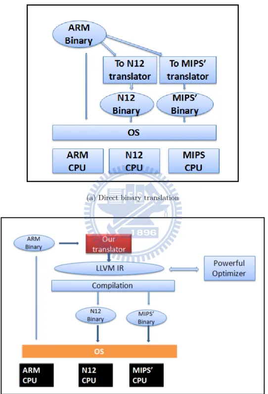
1.1 Translation Categories . . . 6
2.1 CPSR Register Format . . . 8
2.2 7 ARM Processor Modes And All ARM Registers . . . 9
2.3 Instruction Modeling : A Complete ARM Instruction . . . 10
2.4 Condition Field in an ARM Instructon . . . 11
2.5 Instruction Modeling : An ARM load word Instruction . . . . 16
2.6 Runtime Binary Layout . . . 18
2.7 Instruction Modeling : An ARM System Call Instruction . . . 20
2.8 Definition Of syscall Function (Written in ARM assembly code) . . . 20
3.1 Structure Of Address Mapping Table . . . 28
4.1 Runtime Instruction Ratio : After Our Improvement . . . 32
4.2 Runtime Instruction Ratio : After LLVM Optimizations . . . 34
Chapter 1
Introduction
1.1
Dynamic versus Static Binary
Transla-tion Technique
Binary translation, which translates source binary into target binary, is widely used in various applications, such as binary instrumentation [1], run-time optimization [2], ISA migration for new hardware architectures [3] [4], and virtualization environment [5]. Dynamic binary translation has almost become a standard procedure to migrate the general purpose ISA; for ex-ample, Aries [4] migrates PA-RISC binaries to the 64 architecture, IA-32EL [6] migrates IA-32 executables to IA-64. A successful binary translation can reduce the time-to-market requirement for having a large number of ap-plications available on a new developed ISA. Especially in the embedded system field, new embedded architecture has been introduced frequently; as a result, binary translation may become a commonplace in the future. Dynamic binary translation has some difficulties not completely solved like real-time deadline issue, memory wasted in the translation cache. These difficulties may not the serious issues in the general purpose environment,
but they may be unacceptable in the embedded system environment since performance and memory footprint are two critial requirements. The ad-vantage of the static binary translation can avoid the translation overhead at runtime; therefore, a static binary translation system can perform more time-consuming optimizations to improve the code quality and the memory space required for the generated program. Nowadays, more and more em-bedded applications are generated by compilers rather than hand coding; thus, static binary translators can handle the code generated by compiler more easily. In table 1.1, we compare the pro and con of dynamic and static binary translation.
Type Advantages Disvantages
Dynamic Translation Soundness Low efficiency and wasted translation cache Static Translation High efficiency Code discover and code location problem Table 1.1: Comparison Between Dynamic And Static Binary Translation
1.2
Re-Targetability : Direct versus Indirect
Binary Translation
A binary translator could be either direct or indirect. In figure 1.1(a), a direct translator translates source binary into target binary directly [8], ;so a sepa-rate translator is needed for each architecture. In contrast, in figure 1.1(b), an indirect translator first translates source binary into an intermediate repre-sentation (IR) and then translates IR into target binary. The IR offers extra opportunities for optimization. Furthermore, if the IR is well accepted, such as LLVM IR, there could be many existing support modules that we can
use. In the embedded environment, a system with re-targetability makes that retargeting costs little extra overhead. In this study, we take the indi-rect approach. Our experimental system is an ARM-to-ARM static binary translator, which is comprised of two components: a to-LLVM-IR convertor and LLVM infrastructure. We use the to-LLVM-IR translator to translate ARM binary into LLVM IR, leverage existing powerful LLVM optimizations, and convert LLVM IR to target binary with LLVM static code generator. Obviously, our translation system can be easily retargeted to other architec-tures. The only architectural-dependent problem with our system is how to handle system calls in the to-LLVM-IR translator (which will be discussed later).
1.3
LLVM Compiler Infrastructure
Low Level Virtual Machine (LLVM) [10] is a compiler infrastructure devel-oped by University of Illinois. The primary components of the LLVM infras-tructure are a GCC-based C and C++ front-end, a link-time optimization framework with a growing set of global and interprocedural analyses and transformations, static back-ends for many popular architectures, and JIT (Just-In-Time) compilers for several architectures. LLVM also incorporates a low-level object code representation that uses simple RISC-like instructions, but provides rich, language-independent, type information and dataflow in-formation about operands.
1.4
ARM Architecture
ARM, also known as Advanced RISC Machine, is a 32-bit reduced instruction set computer (RISC) developed by ARM Holdings. The ARM architecture is a low-cost, power-efficient microprocessor for embedded control, computing, digital signal processing, games, consumer multimedia and portable applica-tions. This has made them dominant in the mobile and embedded electronics market, about 98 percent of the more than a billion mobile phones sold each year use at least one ARM processor. Almost all famous embedded applica-tions provide the executable compiled for the ARM architecture; as a result, choosing ARM as our source architecture of binary translation is worth doing.
1.5
Research Motivation and Objective
Performance, memory footprint, and re-targetability are crucial issues in the embedded environment. Dynamic binary translation has some difficulties not completely solved like real-time deadline issue, memory wasted in the trans-lation cache. Those defects makes dynamic binary transtrans-lation infeasible in the embedded environment. Direct binary translation costs lots of effort to re-target to a new architecture. Hence, our translator adopts static binary translation which allows us to perform more time-consuming optimizations to improve quality of the generated code. Indirect translation approach en-hances re-targetability of the binary translation system. In conclusion, this thesis aims to build a high-quality and re-targetabe binary translation system suitable in the embedded environment.
1.6
Thesis Organization
In chapter 2, we describe the key translation issues, including register simu-lation, memory access simusimu-lation, system call handling, and indirect branch handling, and summarize the instruction modeling overhead from ARM ISA to LLVM IR. In chapter 3, we disscuss a couple of translation issues, and present improvement to speed up the performance of target ARM binary. In chapter 4, we evaluate the performance of our static binary translation on the EEMBC benchmark. Finally, in chapter 5, we conclude this paper.
(a) Direct binary translation
(b) Indirect binary translation (Our translation System)
Chapter 2
LLVM IR Generation
In this section, we describe the key translation issues from ARM binary to LLVM IR, including register simulation, translation details, memory access simulation, the technical problems and our solutions. Finally, we summarize the instruction modeling overhead from from ARM binary to LLVM IR. Our translator does not handle Thumb instructions and coprocessor instructions since our translator supports user mode only.
2.1
Register Simulation
In order to maintain program behavior and control flow, our translator has to simulate ARM general-purpose registers and the status registers.
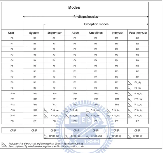
Figure 2.2 shows 7 ARM processor modes and all registers. ARM has 31 general-purpose 32-bit registers. 16 of these registers are visible to applica-tion programs. The remaining registers are reserved for excepapplica-tion processing. Registers r8-r14 are banked, which means that there are multiple copies of these registers. These banked registers are switched among various processor modes. Since our translator supports user-mode applications only, we do not
require all registers in all processor modes but only the 16 general-purpose registers in the user mode.
All processor state other than the general-purpose register contents is held in the status registers. The current operating processor status is in the Current Program Status Register (CPSR). CPSR holds 4 condition flags (Negative, Zero, Carry and Overflow) and other information that we do not require [9]. Figure 2.1 shows the format of CPSR.
Figure 2.1: CPSR Register Format
The target of our translator is LLVM IR [14], which is a virtual instruc-tion set. LLVM IR has no physical registers. Initially, our translator maps 16 general-purpose registers and CPSR to 17 global variables of type inte-ger. However, it is profitable to map the four condition flags in CPSR to four separate global variables. The first reason is that the four condition flags are used and updated frequently: all ARM instructions can be exe-cuted conditionally based on the condition flags and all ALU instructions and comparison instructions may update the condition flags. The second reason, doing register mapping using direct binary translation usually has to consider the number of usable registers in target architecture, but our target LLVM IR is not limited by the number of physical registers; as a result, we can utilize as many as global variables to gain performance.
Obviously, this simple approach to simulate ARM registers will incur tremendous overhead since all operands must be loaded from memory before
Figure 2.2: 7 ARM Processor Modes And All ARM Registers
instruction execution and be stored afterwards. Fortunately, an LLVM op-timizer provides the “promote memory to register” optimization [15]. This promotion can reduce considerable memory accesses.
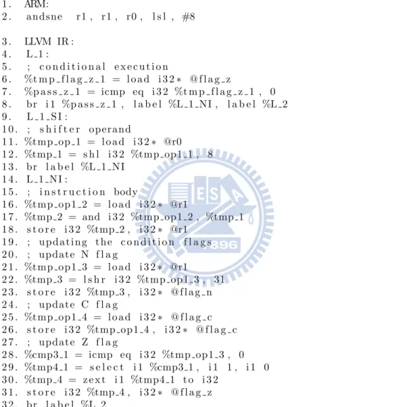
1 . ARM: 2 . andsne r1 , r1 , r0 , l s l , #8 3 . LLVM IR : 4 . L 1 : 5 . ; c o n d i t i o n a l e x e c u t i o n 6 . %t m p f l a g z 1 = l o a d i 3 2 ∗ @ f l a g z 7 . %p a s s z 1 = icmp eq i 3 2 %t m p f l a g z 1 , 0 8 . br i 1 %p a s s z 1 , l a b e l %L 1 NI , l a b e l %L 2 9 . L 1 S I : 1 0 . ; s h i f t e r operand 1 1 . %tmp op 1 = l o a d i 3 2 ∗ @r0 1 2 . %tmp 1 = s h l i 3 2 %tmp op1 1 , 8 1 3 . br l a b e l %L 1 N I 1 4 . L 1 N I : 1 5 . ; i n s t r u c t i o n body 1 6 . %tmp op1 2 = l o a d i 3 2 ∗ @r1 1 7 . %tmp 2 = and i 3 2 %tmp op1 2 , %tmp 1 1 8 . s t o r e i 3 2 %tmp 2 , i 3 2 ∗ @r1 1 9 . ; u p d a t i n g t h e c o n d i t i o n f l a g s 2 0 . ; update N f l a g 2 1 . %tmp op1 3 = l o a d i 3 2 ∗ @r1 2 2 . %tmp 3 = l s h r i 3 2 %tmp op1 3 , 31 2 3 . s t o r e i 3 2 %tmp 3 , i 3 2 ∗ @ f l a g n 2 4 . ; update C f l a g 2 5 . %tmp op1 4 = l o a d i 3 2 ∗ @ f l a g c 2 6 . s t o r e i 3 2 %tmp op1 4 , i 3 2 ∗ @ f l a g c 2 7 . ; update Z f l a g 2 8 . %cmp3 1 = icmp eq i 3 2 %tmp op1 3 , 0 2 9 . %tmp4 1 = s e l e c t i 1 %cmp3 1 , i 1 1 , i 1 0 3 0 . %tmp 4 = z e x t i 1 %tmp4 1 t o i 3 2 3 1 . s t o r e i 3 2 %tmp 4 , i 3 2 ∗ @ f l a g z 3 2 . br l a b e l %L 2
2.2
Translation Detail
In this section, we use the example in figure 2.3 to explain the translation from ARM binary to the corresponding LLVM IR.
2.2.1
Conditional Execution
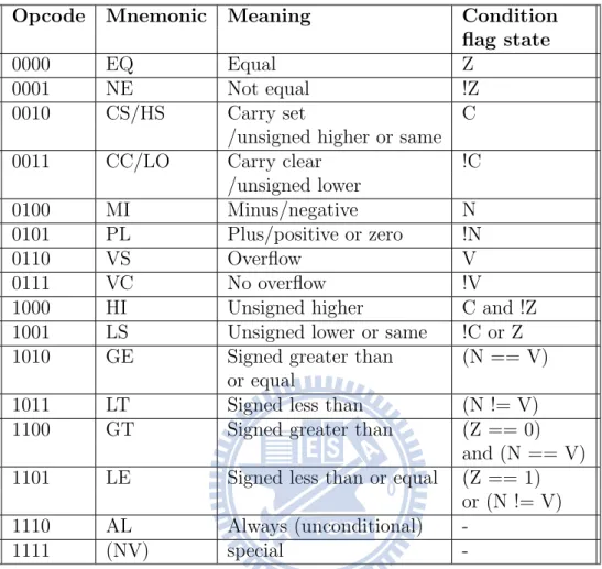
Almost all ARM instructions can be conditionally executed, which means that they have their effects on the program execution state only if the con-dition flags in CPSR satisfy the concon-dition specified in the instruction. Oth-erwise, the instruction acts as a NOP (no operation). Field <cond> in figure 2.4 is the condition field of the instruction. There are 16 combinations of the condition field in an instruction, which are listed in table 2.1.
Opcode Mnemonic Meaning Condition flag state
0000 EQ Equal Z
0001 NE Not equal !Z
0010 CS/HS Carry set C
/unsigned higher or same
0011 CC/LO Carry clear !C
/unsigned lower
0100 MI Minus/negative N
0101 PL Plus/positive or zero !N
0110 VS Overflow V
0111 VC No overflow !V
1000 HI Unsigned higher C and !Z
1001 LS Unsigned lower or same !C or Z
1010 GE Signed greater than (N == V)
or equal
1011 LT Signed less than (N != V)
1100 GT Signed greater than (Z == 0)
and (N == V)
1101 LE Signed less than or equal (Z == 1)
or (N != V)
1110 AL Always (unconditional)
-1111 (NV) special
-Table 2.1: 16 Combinations Of Condition Field
Our translator translates the conditional execution feature into a checking barrier before the instruction execution. The checking barrier checks whether the condition flags in CPSR satisfy the condition specified in the instruction; if it is satisfied then continue the instruction execution, otherwise branch to the next instruction. In Figure 2.3, the condition field of the ARM instruction is NE, which means that the ARM instruction will execute only if the Zero flag is not set.
2.2.2
Shifter Operand
Most data-processing instructions take two source operands. One of them is called a shifter operand, which could be either an immediate value or a register. If the shifter operand is a register, it can have a shift operation applied to it. In Figure 2.3, “r0, lsl #8” is a shifter operand. The value of r0 is logically-shifted-left 8 bits. The resulting value is used as an operand for the andsne instruction. Table 2.2 shows the five shift types in ARM.
Our translator translates the shifted register operand as additional in-structions before the instruction body. In this example, the second source operand r0 will be logically shifted left by 8 before it is used by the AND instruction.
Shift type Meaning Instruction Percentage in the EEMBC
ASR arithmetic shift right 0.94%
LSL logically shift left 2.83%
LSR logically shift right 2.26%
ROR rotate right 0.15%
RRX rotate right with extension 0.14% Table 2.2: 5 Shift(Rotation) Types
2.2.3
Updating Condition Flags
The condition flags in CPSR are usually modified by the comparison in-structions (CMN, CMP, TEQ or TST) and some arithmetic, logical, and move instructions with the S qualifier. Table 2.3 shows the four condition flags and their meaning after instruction execution.
Our translator generates additional instructions to update the condition flags after instruction body if the instruction has the S qualifier. In Figure 2.3, the andsne instruction updates N, Z, and C flags.
Condition flag Value and Meaning N (Negative) Result less than 0 ? 1 : 0 Z (Zero) Result is 0 ? 1 : 0
C (Carry) Operation produced a carry? 1 : 0 Operation produced a borrow? 0 : 1 V (Overflow) Operation has signed overflow ? 1 : 0
2.3
Memory Access Simulation
In this section, we disscuss memory management in target binary. First, we describe static and dynamic memory allocation. Second, we illustrate an example of memory access and present an issue. Third, we propose a solution to improve this issue.
static allocation - our translator keeps the source ARM static section (.text and .data) in the target binary. The purpose is for accessing general data in data section and PC-relative data in text section. We place the source ARM static section at the target address which is the same in the source binary, this decision makes that no extra address computation is needed.
dynamic allocation - Heap and stack allocation are supported by li-brary; as a result, we disscuss the issus of linking approach here. Our source binary is compiled with static linking instead of dynamic linking. Static linking approach makes library become part of our translated code, so it avoids the parameter identification problem and makes our translator more portable in different operating system. Taking an example to explain the parameter identification problem, for example : when translating ”bl printf”, we may translate this call instruction into LLVM ”call i32 (i8*, ...)* @printf(parameter list)”. But, it is difficult to identify the parameter list of printf from source binary. Stack allocation is handled by a function’s prolog and epilog, and those code are also part of our translated code.
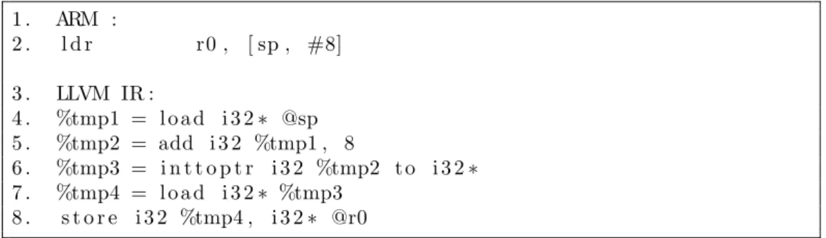
Example and issue In figure 2.5, we illustrate an example of load word instruction. This instruction loads a value from stack and the correspond LLVM IR are easy to be understanded. An intresting issue is if we translate
1 . ARM : 2 . l d r r0 , [ sp , #8] 3 . LLVM IR : 4 . %tmp1 = l o a d i 3 2 ∗ @sp 5 . %tmp2 = add i 3 2 %tmp1 , 8 6 . %tmp3 = i n t t o p t r i 3 2 %tmp2 t o i 3 2 ∗ 7 . %tmp4 = l o a d i 3 2 ∗ %tmp3 8 . s t o r e i 3 2 %tmp4 , i 3 2 ∗ @r0
Figure 2.5: Instruction Modeling : An ARM load word Instruction
stack-operation instructions like general data access, target stack will not be used anymore. (ie. SP register is wasted since variable SP will be mapped to a data register instead of SP register) So, an intresting isssue is whether we should allocate target stack for other purpose ? We will explain our improvement in chapter 3.
2.4
Program Layout
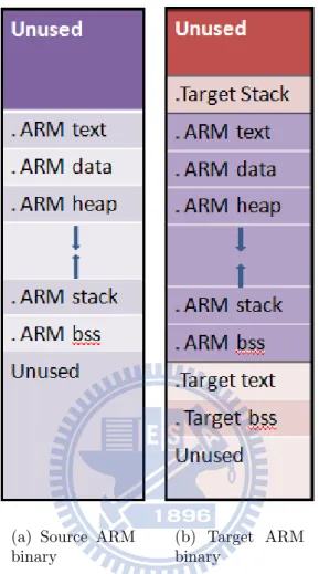
We contrast the runtime layout of the source ARM binary and the target ARM binary in figure 2.6. The target sections can be divided into two parts: the sections of source ARM binary and its own sections. Keeping the source ARM’s text section in target binary is necessary for dynamic translation in the furture, and it also allows the target binary to pc-relative data in the source ARM binary. All the source ARM sections are allocated at the target address which is the same as the address in the source ARM binary. This decision makes the memory accesses much easier to handle since no additional address computation is required for memory access. The part of target section has the text, data, bss section, and stack section. Target data section contains the additional data used to help memory access simulation, target text section contains the generated code and the address mapping table to handle indirect branch, and target stack is allocated to speed up accessing global variables.
(a) Source ARM binary
(b) Target ARM binary
Figure 2.6: Runtime Binary Layout
2.5
System Call Handling
As we have known, system call is a mechanism to communicate between user program and operating system. Each architecture provides different instruction to handle this kind of exception in their defined ISA, such as the Software Interrupt instruction (SWI) in ARM, SYSCALL instruction in MIPS, and INT instruction in x86. Our source architecture ARM provides the Software Interrupt instruction (SWI) to enter Supervisor mode to request a particular supervisor function. Furthermore, user program also has to pass
a number of parameters to operating system such as system call number that indicates which vector in exception vector table will be performed. After operating system finishes its exception service routine, it also returns result to the user program. However, how parameters passed to the operating system and how result returned from operating system are defined by the architecture EABI; for example, ARM architecture passes parameters by registers r0-r3 and returns result of SWI instruction by register r0.
As we have known, the mapping between variables and registers is de-cided by register allocation phase; as a result, the EABI standard introduces a technical restriction in our translator, which is how our translator maps LLVM variables r0-r3 to target physical registers r0-r3 before SWI instruc-tion execuinstruc-tion and maps target physical register r0 back to LLVM variable r0 after SWI instruction execution in order to comply with EABI stardard.
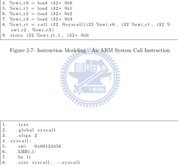
Our translator solves this mapping restriction by translating an ARM SWI instruction into a function call and passing the parameters of system call as the parameters of function call, so that we can utilize ARM procedure call standard. In detail, procedure call standard of ARM and MIPS specifies that physical register r0-r3 are used to hold argument values passed to a procedure call and register r0 also helds result returned from a procedure call.
The codes in figure 2.7 are the corresponding LLVM IR against an ARM SWI instruction, and it does solve the mapping restriction from variables r0-r3 to physical register r0-r0-r3. However, if the definition of syscall function is written using LLVM IR, it won’t solve the mapping restriction from physical register r0 back to variable r0 because the value stored to variable r0 will
1 . ARM: 2 . s w i 0 x00123456 3 . LLVM IR : 4 . %s w i r 0 = l o a d i 3 2 ∗ @r0 5 . %s w i r 1 = l o a d i 3 2 ∗ @r1 6 . %s w i r 2 = l o a d i 3 2 ∗ @r2 7 . %s w i r 3 = l o a d i 3 2 ∗ @r3 8 . %s w i r t = c a l l i 3 2 @ s y s c a l l ( i 3 2 %s w i r 0 , i 3 2 %s w i r 1 , i 3 2 % s w i r 2 , %s w i r 3 ) 9 . s t o r e i 3 2 %s w i r t 1 , i 3 2 ∗ @r0
Figure 2.7: Instruction Modeling : An ARM System Call Instruction
1 . . t e x t 2 . . g l o b a l s y s c a l l 3 . . a l i g n 2 4 . s y s c a l l : 5 . s w i 0 x00123456 6 . . LBB1 1 : 7 . bx l r 8 . . s i z e s y s c a l l , .− s y s c a l l
be the return value of syscall function instead of the return value of ARM SWI instruction since both standards use the same register r0 as their return value. Thus, our translator writes the definition of syscall function in target assembly code to ensure that the value returned from physical r0 is the return value of ARM SWI instruction instead of the return value of syscall function.
2.6
Program Control Management
2.6.1
Indirect Branch Handling
Direct branches can be handled easily in our static translator since their target addresses are known at translation time. Generally speaking, indirect branches are classified as two categories: the structured and unstructured indirect branch. Structured indirect branches are like return-based indirect branches and switch-based indirect branches in the jump table generated by switch statement. Unstructured indirect branches are the others. Typical static binary translator handles return-based indirect branches with Return Address Stack(RAS) [13], switch-based indirect branches by recovering jump table, and unstructured indirect branches with an address mapping table. Our translator adopts the similar ideas to handle indirect branches except Return Address Stack(RAS). In brief, the reason why not to adopt Return Address Stack is that the standard LLVM IR does not support an array of label type; hence, it is hard to implement the Return Address Stack.
2.6.2
Address Mapping Table
Our translator generates an ARM-to-LLVM address mapping table as a spe-cific function to handle return-based indirect branches and other unstruc-tured indirect branches. The table maps the address of an ARM instruction to a corresponding LLVM label when a non-switch indirect branch occurs. In order to minimize the size of the address mapping table, our translator does not keep entries for all ARM instructions. Instead, our translator al-locates an entry for the leading instruction of each recognized basic block
in our imprecise control flow graph. If the target address is not found in the address mapping table, the executing program will throw an exception and abort the process. Indeed, those corner cases will be handled by adding LLVM dynamic components in the future.
In order to speed up the search in the address mapping table, typical static binary translator designs a hash function to index the address map-ping table. However, as we have mentioned before, LLVM does not support an array of label type; as a result, hash function and other search algorithms are infeasible in our binary translation. The only choose to implement the address mapping table is switch statement in LLVM IR. As we have known, if case values in the switch statement are in a narrow range, jump table will be generated, otherwise a sequence of if-else statements are generated. Un-fortunately, our address mapping table is belong to latter switch statement, so the program must do linear search in the address mapping table.
2.7
Summary of Instruction Modeling
Over-head
In this section, we list some instruction medeling which cost a sequence of LLVM IR.
1. Register Simulation
As we have mentioned in subsection ”register emulation”, our translator uses the global variables to emulate ARM physical registers. Therefore, the generated program must load the source operands from memory before instruction execution, and store the destination operand back to memory. We can imagine this does create a huge burden.
2. Redundant Condition Flag Update
It is possible for our translator to generate code that updates only the flags that will be used later. In Figure 2.3, assume that only the Z flag of the andsne instruction will be used later. It is not necessary to generate code that updates the N and C flags. Our translator will generate code that updates all three flags. We will rely on an existing opimization pass ”global value numbering” in LLVM that will remove the unnecessary code.
3. Updating Condition Flags and Shifter Operand
There are some special operations in ARM ISA such as ROR(32 bits rotation), RRX(33 bits rotation) in shift type, and carryFrom, bor-rowFrom, overflowFrom [9] in order to update condition flags. Our translator must emulate single operation of those with several LLVM
IR; however, the frequency of those instructions on the EEMBC bench-mark is pretty rare; thus, those instructions don’t impact performance of the whole binary translation system.
4. Accessing Multiple Registers
ARM architecture is capable of loading multiple and storing multiple registers. Those instructions perform a block transfer of any number of the general-purpose registers to or from memory. LLVM IR does not provide the similar feature for our translator to do semantic mapping; as a result, our translator translates a Load Multiple(LDM) and Store Multiple(STM) instruction into a sequence of Load(LDR) and Store Register(STR) instructions.
Chapter 3
Translation Issues And
Improvement
3.1
Target Stack Allocation
The defect of our proposed solution to simulate memory access is that SP(Stack Pointer) register won’t be used anymore because we didn’t use the target stack to simulate the source stack. Registers are the valuable resource of CPU; accordingly, our translator allocates target stack to access all simu-lated global register and data (16 ARM registers, 4 condition flags. The reason is that ARM architecture requires two load instructions to accessing a global variable, one is for loading the address of the global variable, and the other is for loading the value. Therefore, we allocate the target stack in our translated binary and copy all global variables onto the target stack in order to accelerate the access of all global variables. Accessing a local variable from stack requires merely one load instruction with the help of SP register. This improvement shows great profit in the generated program since accessing the global variable is necessary before and after translating each ARM instructions.
3.2
Address Mapping Table Improvement
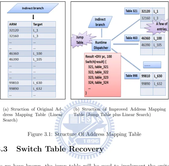
Performing a linear search in the address mapping table would cause a bottle-neck in our generated programs; hence, our translator improves the design of the address mapping table. First, our translator divides the address mapping table into a lot of smaller address mapping tables according to the quotient of the ARM PC divided by the value of a predefined divisor. Second, a non-switch indirect branch would jump to a runtime dispatcher. This runtime dispatcher would perform the same operation to obtain a result as the way to divide the address mapping table. Then, this result would be used to index a jump table to decide which address mapping table should be searched. The key to speed up the linear search in each address mapping table is to decide the value of the predefined mask, so that each smaller address mapping table contains only a couple of entries. With this improvement, the time spent on the address mapping table in our translator is approaching the time spent on the address mapping table using hash algorithm in other binary translator. Figure 3.1 contrasts the structure of original address mapping table against our improved address mapping table.(a) Struction of Original Ad-dress Mapping Table (Linear Search)
(b) Struction of Improved Address Mapping Table (Jump Table plus Linear Search)
Figure 3.1: Structure Of Address Mapping Table
3.3
Switch Table Recovery
As we have known, the jump table will be used to implement the switch statement if case values are in a narrow range. The indirect branch in the jump table used to index the target address is named as switch-based indirect branch. Although this kind of indirect branches can be handled by our address mapping table, our translator still recovers the jump tables in the ARM binary to speed up the generated programs [7].
Chapter 4
Experiments And Results
In this chapter, we list our simulation environment, the benchmark, and the result of performance evaluation. Due to the toolchain constraints, we choose LLVM ARM backend as our target architecture to faithfully reflect the performance of our translation system.
4.1
Experimental Environment
Our experiment translates the source ARM binary into the target ARM bi-nary. The benchmark we use in the experiment is the EEMBC [12] suite ver-sion 1.1. EEMBC benchmark standardizes on real-world, embedded bench-mark software to help designers select the right embedded processors for their systems. The EEMBC benchmark is consist of six suites: 8-16 bit, automotive, consumer, networking, office, and telecom. We compile 55 test programs in the EEMBC benchmark as lite versions in order to speed up our simulation. The cross compiler for ARM applications is GCC 3.4.3 with static linking, and we use a modified GDB 6.8 [11] to verify ARM binaries and target ARM binary, and to help data collection. The version of LLVM
we used is version 2.5.
4.2
Experimental Results
In this section, we evaluate the performance of our translation system. Fig-ure 4.1 shows the performance of the baseline translation and our improve-ment. Figure 4.2 shows the performance after each LLVM optimization we leveraged.
4.2.1
Runtime Instruction Ratio : After Our
Improve-ment
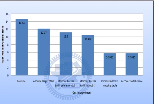
1. Baseline translation
Our translation system can correctly translate all programs in the EEMBC benchmark, and we show the performance gain of each im-provement we mentioned in chapter 3 in figure 4.1; for example, the performance of the baseline translation, which is labeled as ”baseline translation” is 14.64 on the EEMBC benchmark. The number 14.64 means the number of the runtime instructions of the source ARM bi-nary to the number of runtime instructions of the target ARM bibi-nary is 14.64. In other words, for each ARM instruction, on average, the baseline translation takes 14.64 target ARM instructions for simula-tion. The figure of 14.64 shows the tremendous instruction modeling overhead from ARM binary to LLVM IR.
2. Allocate target stack
access all simulated ARM registers since accessing a local variable from stack requires merely one load instruction with the help of SP register. After the improvement,the performance ratio is reduced to 12.17 on the EEMBC benchmark. This improvement shows great performance gain for our translation system.
3. Memory Approach
We present two approaches to simulate memory access. First is using LLVM getelementptr. Second is using LLVM inttoptr. Both approaches can correctly simulate memory access, but later approach can achieve better performance. After the improvement, the performance ratio is reduced to 10.48 on the EEMBC benchmark.
4. Improve Address mapping table
In baseline translation, since LLVM doesn’t support an array of label type, performing a linear search in the address mapping table is re-quired. Our translator re-designs the expression of address mapping table by adding a runtime dispatcher. After the improvement, the per-formance ratio is reduced to 5.7623 on the EEMBC benchmark.
5. Recover Switch Table
In baseline translation, switch-based indirect branches are handled by the address mapping table. Our improvement recovers the jump table in the source ARM binary so that switch-based indirect branches are no longer handled by the address mapping table. After the improvement, the performance ratio reduces 0.0008 fold to reach 5.7615 fold on the
EEMBC benchmark. The EEMBC benchmark rarely uses the switch statement; this is why the improvement is nearly zero after recovering the switch table.
Figure 4.1: Runtime Instruction Ratio : After Our Improvement
4.2.2
Runtime Instruction Ratio : After LLVM
Opti-mizations
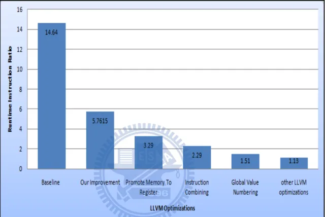
1. LLVM Optimization - Promote Memory To Register One of the mo-tivations to adopt LLVM compiler infrastructure is its powerful opti-mizations. we show the performance gain of each LLVM optimization figure 4.2. In the section ”reigster simulation”’, we map 16 ARM regis-ters and 4 condition flags to LLVM global variables. Thus, we load the
value of the source registers from memory before instruction body and store the value back to the destination register afterward. This simple approach makes implementation more easier, but it introduces serious redundent memory access. In this section, we utilize LLVM ”Promote Memory To Register” optimization to eliminate redundent memory ac-cess. After this LLVM optimization, the performance ratio is reduced to 3.29 on the EEMBC benchmark. (Note: Our experiment merely uses 43 programs out of the EEMBC benchmark to perform LLVM optimizations; the reason is that some aggressive LLVM optimizations will produce incorrect output.)
2. LLVM Optimization - Instruction Combining This optimization com-bines instructions to form fewer, simple instructions. For instance, ”add X, X” or ”mul X, 2” are transformed into ”shl X, 1”. ”%Y = add i32 %X, 1” and ”%Y = add i32 %X, 1” are transformed into ”%Z = add i32 %X, 2” After this LLVM optimization, the performance ratio reduces 1 fold to reach 2.29 fold on the EEMBC benchmark.
3. LLVM optimization - Global Value Numbering In the section ”Trans-lation Detail”, we illustrate an example of redundent condition flag update. we leave this opportunity to LLVM ”Global Value Number-ing” optimization. This optimization eliminates fully and partially re-dundant instructions. After this LLVM optimization, the performance ratio reduces 0.78 fold to reach 1.51 fold on EEMBC benchmark.
generated code. Finally, the runtime instruction ratio can reach 1.13 fold on the EEMBC benchmark.
Figure 4.2: Runtime Instruction Ratio : After LLVM Optimizations
4.2.3
Binary Size Ratio
In figure 4.3, it shows the ratio of the static code size of the target ARM binary to the source ARM binary; for example, Label Text means the static size of .text section in target ARM binary is 2.45 times the ratio of the static size of .text section in source ARM binary, label Data means the static size of .data section in target ARM binary is 10.23 times the ratio of the static size of .data section in the source ARM binary and label Total means the
static size of target ARM binary is 2.62 times the ratio of the static size of the source ARM binary. The text section in the target ARM binary contains the address mapping table to handle indirect branch thus the code size is a little bigger than the text section of the source ARM binary. The target ARM binary’s data section contains all source ARM binary’s sections, so the code size ratio is of 10.23 fold.
Chapter 5
Conclusion
5.1
Limitation Of Our Translator
In this section, we list some limitation of our re-targetable static binary tranl-sator.
1. Source binary should be compiled with static linking.
2. Our translator supports user mode only. Co-processor mode and thumb mode are not supported.
3. Applications should be performed on the same operating system envrion-ment. (ie. library should be the same version.)
4. Self-Referencing and Self-modifying code are not supported because the code actually executing is translated code, not the original source code. Our translated code did’t simulate the same behavior of these code.
5. Source binary should be compiled with static linking to avoid parameter identification problem.
6. Our translator aims to translate the compiler-based applications. Hand-coded applications may incur code location problem which cannot be cor-rectly handled by our address mapping table.
5.2
Conclusion
Dynamic binary translation is usually used to migrate applications to new architectures; however, dynamic binary translation has some difficulties not completely solved like real-time deadline issue, memory wasted in the trans-lation cache. Hence, we develop a static binary transtrans-lation system so that we can perform more time-consuming optimizations to improve the qual-ity for the generated code. Direct binary translation lacks re-targetabilqual-ity, so developming a re-targetable static binary translation is promising on the embedded system environment.
The ARM architecture has some features that must be handled carefully in binary translation; for instance, the conditional execution instructions, the condition flag updates. We also pointed out the key challenges to perform the indirect binary translation from a lower level ARM ISA to a higher level LLVM IR. Our translator not only overcomes the challenges but also presents some issues that can affect the performance of the generated program. Our baseline ARM-to-ARM translation without the special improvements and LLVM optimizations achieves runtime instruction ratio of 14.64 on EEMBC benchmark, after our improvements for LLVM IR generation, the runtime instruction ratio is reduced from 14.64 fold to 5.76 fold. Furthermore, after we leverage the powerful LLVM optimizations, the runtime instruction ratio is reduced from 5.76 fold to 1.13 fold.
Our re-targetable static translation system shows great performance on the EEMBC benchmark thus we are confident that developing a re-targetable static binary translation system is promising.
Bibliography
[1] Kim Hazelwood and Artur Klauser. ”A Dynamic Binary Instrumentation Engine for the ARM Architecture,” in Proceedings of the 2006 ACM International Conference on Compilers, Architecture, and Synthesis for Embedded Systems (CASES). Seoul, Korea. October 2006, pages 261-270
[2] Toshio Suganuma, Toshiaki Yasue, Motohiro Kawahito, Hideaki Ko-matsu, Toshio Nakatani: A Dynamic Optimization Framework for a Java Just-In-Time Compiler. OOPSLA 2001: 180-194
[3] Chernoff, Anton and Herdeg, Mark and Hookway, Ray and Reeve, Chris and Rubin, Norman and Tye, Tony and Yadavalli, S. Bharadwaj and Yates, John. ”FX!32: A Profile-Directed Binary Translator”, Micro, IEEE, Vol. 18, No. 2. (1998), pp. 56-64.
[4] Cindy Zheng, Carol Thompson, ”PA-RISC to IA-64: Transparent Ex-ecution, No Recompilation,” Computer, vol. 33, no. 3, pp. 47-52, Mar. 2000
[5] Keith Adams, ”A comparison of software and hardware techniques for x86 virtualization”, in ASPLOS-XII: Proceedings of the 12th international conference on Architectural, pp 2-13, 2006
[6] Baraz, L. Devor, T. Etzion, O. Goldenberg, S. Skaletsky, A. Yun Wang Zemach, Y. ”IA-32 Execution Layer: a two-phase dynamic translator designed to support IA-32 applications on Itanium-based systems”, Mi-croarchitecture, 2003. MICRO-36. Proceedings. 36th Annual IEEE/ACM International Symposium, 2003, page 191-201
[7] Cristina Cifuentes and Mike Van Emmerik, ”Recovery of Jump Table Case Statements from Binary Code”, Proceedings of the 7th International Workshop on Program Comprehension, p192, 1999
[8] Jiunn-Yeu Chen, Wuu Yang, Tzu-Han Hung, Charlie Su, Wei-Chung Hsu, ”On Static Binary Translation and Optimization for ARM-based application”, the 6th Workshop on Optimizations for DSP and Embedded System(ODES), April 2008
[9] ARM Architecture Reference Manual, Addison-Wesley, 2001
[10] Chris Lattner and Vikram Adve, LLVM: A Compilation Framework for Lifelong Program Analysis & Transformation, Proceedings of the 2004 In-ternational Symposium on Code Generation and Optimization (CGO’04), Palo Alto, California, Mar. 2004.
[11] GDB, ”The GNU Project Debugger”, from
http://www.gnu.org/software/gdb/
[12] EEMBC, ”The Embedded MicroProcessor Benchmark Consortium”, from http://www.eembc.org/home.php
[13] James Smith and Ravi Nair, Virtual Machines: Versatile Platforms For Systems And Processes, 2005
[14] LLVM Language Reference Manual, from
http://llvm.org/docs/LangRef.html
[15] LLVM’s Analysis and Transform Passes, from
http://llvm.org/docs/Passes.html
[16] Earnshaw, R. (2005, October). Procedure Call Standard for the ARM Architecture. Retrieved May 1, 2006, from http://www.arm.com/products/DevTools/ABI.html