行政院國家科學委員會專題研究計畫 成果報告
新型大伸展式微致動器的研究(I)
計畫類別: 個別型計畫 計畫編號: NSC91-2212-E-009-036-執行期間: 91 年 08 月 01 日至 92 年 07 月 31 日 執行單位: 國立交通大學機械工程學系 計畫主持人: 徐文祥 計畫參與人員: 許鎮鵬, 廖挺欣, 林正軒 報告類型: 精簡報告 處理方式: 本計畫可公開查詢中
華
民
國 92 年 8 月 7 日
新型大伸展式微致動器的研究
NSC91-2212-E-009-036
交通大學機械工程學系 徐文祥
中文摘要 關鍵字:微致動器,電熱動式,大伸展,撓性結構,微電鑄 本計畫提出一具有特殊撓性結構設計的新型電熱式大伸展式微致動器。其結 構緊密、不占大面積,與以往相關文獻提出的平面運動微致動器設計相比,在此 提出的微致動器能在緊密面積下,明顯產生更大輸出,位移輸出效率每毫米平方 面積可達 200 微米,及數百微牛頓之出力。此致動器操作電壓小於四伏特,最大 工作溫度小於 350°C,並且可達 100 Hz 的工作頻率(3 伏特)。在結構設計方面, 利用有限元素分析軟體,分析關鍵之結構幾何尺寸:曲樑角度、拘束樑寬度,與 位移輸出之關係。基本上,此一高效率之致動器,可經由增加串連的驅動單元數 目,明顯增加總體元件位移輸出,而僅需增加些微的元件面積。 英文摘要An electrothermally-driven long stretch micro drive (LSMD) is presented for in-plane rectilinear motions in hundreds of micrometers with very compact arrangement. High output performance (output displacements over device area excluding electrical contact pads) of 200 µm/mm² has successfully achieved for devices made of 10~12 µm thick electroplated nickel. The proposed device (N=5) features large output displacements with low operation temperatures (< 350°C) and driving voltages (< 4 volts). It can be operated up to 100 Hz at 3 volts without displacement degradations. Experiments and simulations are conducted to verify two design issues, bent beam angle and constraint bar width, with good agreements. The output displacements can be effectively magnify by cascading more actuation units in cascaded structures of the micro drive.
1. INTRODUCTION
A micro actuator with larger output displacement and force at a compact size is
single micro actuator usually can provide only limited output force and displacement. Therefore, proper integration of several basic actuators into an arrayed structure becomes an
arrayed microactuators to magnify both output displacement and force are often called artificial muscles or muscle-like micro actuators [1,2], which require complicated micromachining techniques. In many applications, a larger displacement is necessary with a smaller but adequate force as trade-off [3,4]. Therefore, large displacements actuators with adequate forces in arrayed and integrated structures had been reported. Arrayed electro-thermal actuators [5,6] have been reported with limited output displacements. For non-silicon-based machining methods, microactuators driven by piezoelectric [7,8], shape memory effect [9,10], and magnetic actuation principles [11] have been published. However, these non-silicon-based machined actuators were all in the millimeter to centimeter scale and still not feasible in batch fabrication process.
Here electro-thermal micro actuators with cascaded actuation units are designed, analyzed, fabricated and tested. Comparing to previous in-plane micro actuators, the proposed micro drives are expected to provide larger displacement at IC-level driving voltage and compact device size. From previous studies [12], the proposed LSMD with V-shaped actuation bent beams are simpler in design and have larger output displacement than cosine-shaped ones. Besides, thick Ni devices show lower driving voltages and longer displacements than 2µm-thick polysilicon devices. A finite element model is constructed to study the thermal mechanical behaviors and transient thermal response here.
CONCEPT DESIGN
The proposed micro drive consists of a pair of cascaded structures in parallel, as shown in Fig. 1(a). Hence total output force can be doubled. By connecting several actuation units in series, two cascaded structures can be constructed. Each actuation unit is formed by two actuation bent beams and a constraint bar, as shown in Fig. 1(b), where the primary geometry parameters are also defined. By applying electrical potentials across anchor 1 and anchor 2 to form a close loop, actuation bent beams subjected to joule heating will expand and push the device to stretch outward. The constraint bar in the proposed device is used to reduce the movement at two ends of actuation bent beams. Generally, more actuation units in cascaded structures can effectively magnify the output displacements of the micro drive. The key limitation comes from the fabrication capability. It should be noted that the design of constraint bar is critical in output magnification. Since the movement at two ends of actuation bent beam will affect the output displacement directly. Besides, constraint bar is a compression member in the device, therefore, mechanical strength should be considered in design.
(b)
F igure 1. a) Concept design of the proposed
LSMD (N= 5). b) The basic actuation unit and geometrical parameter definitions.
FINITE ELEMENT SIMULATION
Simulation by ANSYS 5.5. includes two steps, first is electro-thermal analysis with 3-D Solid69 element and followed by thermal stress analysis with 3-D Solid45 element. The finite element model is half-symmetry for efficiency. In electro-thermal analysis, reference temperature is set to be 20°C and silicon substrate, silicon-oxide spacer, air-gap and air-ambient are all considered in conductive heat transfer mode. Thermal conductivity and specific heat of air are temperature-dependent that significantly alters the simulated temperature results and profiles [13]. The thermal conductivities and CTEs (coefficients of thermal expansion) of nickel and single-crystalline silicon (SC-Si) are also temperature-dependent in simulations. Thermal convection is not considered due to contributions in heat transfer are neglectful [13,14]. Owing to low operation temperatures of LSMD (limited to below 350°C for Ni structures to prevent degrading in air [3]), thermal radiation is also neglected. In thermal stress analysis, output displacements are simulated by loading temperature profile resulted from
thicker devices can provide larger output displacements and forces at constant dc driving voltage, as shown in Fig. 2.
FABRICATION
The devices are fabricated by nickel electroforming with only one mask for the benefit of thick and strong mechanical strength to overcome out-of-plane displacements or buckling and stiction problems during releasing-drying processes and in-use conditions. Besides, electroplated Ni has high coefficient of thermal expansion about 12.7-16.8 ppm/K and low electrical resistivity of 80-130 nW-m, which is desirable for thermal actuators.
F igure 2. Simulated output displacements and
forces of Ni LSMD with various structure thickness. (W=8 µm, θ=1.0°, D=34 µm)
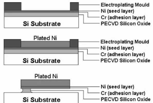
Fabrication process is illustrated in Fig. 3. The devices are fabricated on a SC-Si substrate with 6 µm thick PECVD (plasma enhanced chemical vapor deposition) silicon-oxide isolation and sacrificial layer deposited. Then Cr/Ni (200 Å /1500Å ) are evaporated as seed layer. The Ni structures
using a nickel sulfamate solution with Ni concentration of 400g/L. Before plating, the photoresist molds are immersed in DI water for 5-10 minutes to ensure the solutions flow into the bottom of molds. Electroforming is performed at 47.5-52.5°C with current densities of 8.5-10 mA/cm². Ni of 10-12 µm in thickness is achieved in 90 min. The photoresist molds are subsequently stripped in acetone, then the seed and sacrificial layers are etched to release the devices. The devices are then rinsing in DI water 10 minutes and drying in IPA solutions at 120°C hot plate for 5-10 minutes. The mask line width is broadened after UV photolithography. Therefore, Ni LSMDs with actuation bent beams of 6-8 µm in width are obtained.
F igure 3. Electroforming process to fabricate
Ni LSMD with one mask.
TESTING RESULTS AND DISCUSSIONS
Testing is performed under optical microscopy to measure static output displacements. Resolution on displacement calibration is 1.5 µm. All tested devices consist five actuation units (N=5) in each pair of cascaded structures where span of actuation bent beam (L) is 1000 µm. Generally, the device sizes excluding electrical contact pads
are all below 1 mm² for bent angles θ in the range of 0.2°-1.0°.
Figure 4 shows optical photos of the Ni device with dimensions of 8.0 µm bent beam width, 34 µm constraint bar width, and bent angle of 0.2° before and after actuation. Longest stretch up to 215 µm is measured for the device at driving dc voltage of 3 volts and current of 300 mA.
Figure 5 shows the measured and simulated load-deflection curves of the devices with bent beam width of 8 µm at two different bent beam angles. The load-deflection relations are quite linear in the range of 0.5-3.0 volts, and the simulated maximum temperature is below 300°C at 3.0 volts.
Simulations on two design issues are discussed and verified by experimental data. It shows in Fig. 6, smaller bent beam angles (θ) will increase output displacements significantly. However, if bent beam angles are too small, the actuation bent beams will become unstable.
Figure 7 shows the influences of constraint bar width (D) on output displacements. It is found that a wider constraint bar will get larger output displacements. However, increasing constraint bar width will get only limited improvements in displacements and raise device areas. For instance, at 3 volts, increasing constraint bar width from 14 µm to 24 µm improves displacements by 10.3% and 2.2% in experiment and in simulation respectively. If the constraint bar width is less than 14 µm, the temperature of constraint bar will be higher than that of wider one under the same input voltage, and significantly decreases the output displacement. For example, decreasing constraint bar width from
14 µm to 8 µm, output displacements are dramatically depressed by 56.5% and 48.1% in experiment and in simulation respectively. Besides, in-plane buckling of constraint bars narrower than 14 µm strongly depresses the outputs and that are observed in testing and confirmed by simulations.
In dynamic testing, it is found that the device (W=8 µm, θ=1°, D=34 µm, V=3 volts) can be operated up to 100 Hz without significant degradation in displacements. Figure 8 shows simulated thermal transient response of the device under step input of 3 volts for 20 ms. The vertical axis represents peak temperature of the device that occurs at connecting-part between actuation bent beams. The thermal rise time is about 10 ms in simulation that confirms the dynamic testing observation.
(a) Over view.
(b) Close-up view of the indicator.
F igure 4. Operation of the Ni LSMD up to
215µm at 3 dc volts. a) Over view. b) Close-up view. (W=8 µm, θ=0.2°, D=34
µm)
F igure 5. Measured and simulated results of
voltage-load and displacement data. (W=8 µm, D=34 µm)
F igure 6. Measured and simulated results of
devices (W=8 µm, D=34 µm, V= 3 volts) with various bent angles θ.
F igure 7. Measured and simulated results of
F igure 8. Simulated transient thermal
response of Ni LSMD at 3 dc volts for 20 ms.
References
[1] Esashi, M., Yamaguchi, M., Kawamura, S. and Minami, K., “ Control of distributed electrostatic microstructures,” J. Micromech. Microeng., Vol. 3, pp.90-95, 1993.
[2] Yadon, L.N., Jacobson, J.D., Goodwin-Johansson, S.H., Bobbio, S.M. and Bartlett, C.A., “ Integrated force arrays: theory and modeling of static operation,” J. Microelectromechanical systems, Vol. 4, No.
3, September 1995.
[3] Chu, Larry L., Hetrick, Joel A., Yogesh, B. and Gianchandani, Y. B., “ High amplification compliant microtransmissions for rectilinear electrothermal actuators,” Sensors and Actuators A, 97-98, pp. 776-783, 2002.
[4] Park, J.S., Chu, L.L., Oliver, A.D. and Gianchandani, Y. B.,” Bent-beam electrothermal actuators---part II: linear and
rotary microengines,” J.
Microelectromechanical systems, Vol. 10, No.
2, pp.255-62, June 2001.
[5] Judy, J. W., Tamagawa, T. and Polla, D. L., “ Surface micromachined linear thermal microactuator,” Proc. IEEE pp. 629-632,
1990.
[6] Ananthasuresh, G.K. and Moulton, T., “ Micromechanical devices with embedded electro-thermal-compliant actuation,” Sensors and Actuators A, 90, pp.38-48, 2001.
[7] Claeyssen, F. and Letty, R.L., “ Piezoactuators and piezo motors for high strokes/precise positioning applications,”Proc. Actuator 98 Conf., Pub Messe Bremen,
Germany, pp. 170-73, 1998.
[8] Claeyssen, F., Letty, R.L., Barillot, F., Lhermet, N., Fabbro, H., Guay, P. and Yorck, M., “ Mechanisms based on piezo actuators,”
Proc. Actuator 2000 Conf., Pub Messe Bremen, Germany, pp. 456-59, 2000.
[9] Mineta, T., Mitsui, T., Watanabe, Y., Kobayashi, S., Haga, Y. and Esashi, M., “ Batch fabricated flat meandering shape memory alloy actuator for active catheter,”
Sensors and Actuators A, 88, pp. 112-120,
2001.
[10] Kohl, M. and Skrobanek, K.D., “ Linear microactuators based on shape memory effect,” Sensors and Actuators A, 70, pp.
104-11, 1998.
[11] Frank, T. and Schilling, C., “ The development of cascadable microdrives with muscle-like operating behaviour,” J. Micromech. Microeng., Vol. 8, pp.222-29,
1998.
[12] Hsu, C.-P., Tai, W.-C. and Hsu, W., “Design and analysis of an electro-thermally driven long-stretch micro drive with cascaded structure,” ASME IMECE, New Orleans,
Louisiana, November 17-22, 2002.
[13] Lott, C.D., McLain, T.W., Hard, J.N. and Howell, L.L., “ Modeling the thermal behavior of a surface-micromachined linear-displacement thermomechanical
microactuator,”Sensors and Actuators A, 101,
pp.239-250, 2002.
[14] Lin, L. and Chiao, M., “ Electrothermal
responses of lineshape microstructures,”