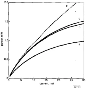
ments were performed under continuous DC current with devices mounted on TO-5 headers. No heat sinking was employed. Fig. 2 shows the power as a function of current emitted from samples (a), (b) and (c). The detuned samples can be seen to give more power than the tuned sample over all currents. For the detuned devices, the peak external quantum efficiency is just over 6% for currents below lmA, giving around O.lmW, whilst at 5mA, the efficiency is still a modest 5.4%, giving OSmW of power. Even at 13mA, where the device emits 1mW of power, the efficiency is still 4%. The peak efficiency for the tuned device is 4.5% at currents below I d , giving around 0.lmW of power. To deliver OSmW of power, we find that a current of 8mA is required, and the effi- ciency is 3.2%. External wall-plug efficiencies are similar in value to those stated for external quantum efficiencies. Fig. 2 also shows the output power for the 4nm detuned sample under pulsed current injection, with a l o p long current pulse and lms period. This indicates the increase in power that would be available if the device were to be adequately heat sunk.
60 50 4 4 0 - E pi’
$
30- c 20 10 0 2. 1.z
I-- $ 1.g
0.-
-
--
1.6 1.7 i .a 1.9.-
b -1- ,.*.
I’ C 5 10 15 20 25 current, mAFig. 2 Output power for tuned, 4nm detuned and 6nm detuned RCLED
under DC current injection a Tuned, DC current b 4nm detuned, DC current
b’ 4nm detuned sample under pulsed current injection, using lops
long current pulse and 1 ms period (giving 1% duty cycle)
c 6nm detuned, DC current
1877/31
voltage, V
Fig. 3 I/V characteristics for tuned, 4nm detuned and 6 nm detuned RCLED
tuned - . - 4nm detuned . . . 6nm detuned
Fig. 3 shows the I-V characteristics for the RCLEDs under for- ward bias. Voltages are between 1.7 and 1.9V in the current range MOmA. The low turn-on voltages are attributed to the high lev- els of carbon doping achieved in the p-type layers.
Conclusion: We have demonstrated high eficiency, low-voltage
RCLEDs operating at 650 nm [Note 11.
Acknowledgments: The authors would like to thank G. Hill (Shef-
field) for the processing of devices. This work is supported by the U.K. Engineering and Physical Sciences Research Council (EPSRC).
0 IEE 2000
Electronics Letters Online No: 20001182
DOI: 10. 1049/el:20001182
J.W. Gray, Y.S. Jalili, P.N. Stavrinou, M. Whitehead and G. Parry
(Centre for Electronic Materials and Devices, The Blackett Laboratory, Imperial College of Science, Technology and Medicine, London S W7 2BZ, United Kingdom)
A. Joel, R. Robjohn, R. Petrie, S. Hunjan, P. Gong and G . Duggan
(Epitaxial Products International Ltd., Cypress Drive, St. Mellons, Cardiff CF3 OEG, United Kingdom)
28 June 2000
References
DE NEVE, H., BLONDELLE, J., BAETS, R., DEMEESTER, P., VAN DAELE, P., and BORGHS, G.: ‘High efficiency planar microcavity LED’s: comparison of design and experiment’, IEEE Photonics
Technol. Lett., 1995, 7, (3), pp. 287-289
LOTT, J.A., SCHNEIDER, R.P., VAWTER, G.A., ZOLPER, J.c., and MALLOY, K J.: ‘Visible (660 nm) resonant-cavity light-emitting diodes’, Electron. Lett., 1993, 29, (4), pp. 328-329
STREUBEL, K., HELIN, U , OSKARSSON, v., BBCKLIN, E., and JOHANSSON, A.: ‘High brightness visible (660 nm) resonant-cavity light-emitting diode’, IEEE Photonics Technol. Lett., 1998, 10, (12),
SNOWTON, P.M., and BLOOD, P.: ‘GaInP-(A1,Gal,)InP 670 nm quantum-well lasers for high-temperature operation’, ZEEE J. Quantum Electron., 1995, 31, (12), pp. 2159-2164
STAVRINOU, P.N., WHITEHEAD, M., PARRY, G., and BUTTON, c.c.: ‘Angular spectrum of visible resonant-cavity light-emitting diodes’, pp. 1685-1687
J. Appl. Phys., 1999, 86. (6), pp. 3475-3477
SIPILA, P., SAARINEN, M., GUINA, M., VILOKKINEN, V., TOIVONEN, M., and PESSA, M.: ‘Temperature behaviour of resonant cavity light- emitting diodes at 650 nm’, Semicond. Sci. Technol., 2000, 15, pp. 418421
Fast feedforward channel sounding
RAKE
receiver
Chun-Chyuan Chen and Chia-Chi Huang
A RAKE receiver with a feedforward channel sounding technique
is described. Chip rate sampling is used to reduce the hardware complexity. A novel path-selection technique is employed to track
the rapidly changing channel impulse response. The bit error rate performance of this RAKE receiver was evaluated by computer simulation.
Iritroduction: In a CDMA system, a RAKE receiver combats the effect of multipath fading by resolving and optimally combining major multipath components [l]. Within a conventional RAKE receiver, the pseudonoise (PN) code synchronisation is usually achieved in two steps, i.e. acquisition and tracking. Code acquisi- tion achieves coarse code phase alignment, within a fraction of a chip period, between a locally generated PN code and a received PN code. Conversely, code tracking achieves fine code phase alignment between the two PN codes and it is usually imple- mented with a delay-locked loop (DLL) scheme [2]. Because a DLL scheme induces a delay from its feedback process, its
Note 1: Since the submission of this Letter, we have learned of a similar report describing 650nm RCLEDs grown by molecular beam epitaxy, which have com- parable performance characteristics to the devices decribed here [6].
performance greatly degrades while a multipath channel changes rapidly.
In this Letter, we propose a fast feedfonvard channel sounding RAKE receiver. We adopt a novel path selection technique to track the fast changes of the multipath fading channel. The pro- posed receiver has low complexity and works well in a fast fading multipath channel.
System model: In a direct sequence spread spectrum (DS-SS) sys- tem, we assume a pilot signal is transmitted with a data signal to estimate the channel. The transmitted baseband signal S)(t) for the ith data symbol period can be represented by
where Np is the length of the PN code, dCp is the gain of the pilot signal relative to the data signal, Cp,, is the nth chip of the pilot PN code, C , , is the nth chip of the data PN code, di) is the ith data symbol (+1 or -l), P(t) is the transmitted pulse shaping func- tion, and T, is the chip period. We also assume the pulse shaping filters at the transmitter and the receiver are both squared root raised cosine filters. The transmitted signal is oversampled and sent through a multipath fading channel model which includes the effect of the two squared root raised cosine filters. We decimate the received signal into one sample per chip before it is fed to the proposed RAKE receiver.
digital input
Yin -
Proposed RAKE receiver: As shown in Fig. 1, the proposed
RAKE receiver includes a multipath searcher, a channel sounding subsystem, a pilot interference cancellation block, and a data sig- nal detection block. The multipath searcher estimates the power delay profile of the multipath channel and sends it to the channel sounding subsystem every search period Tsearch. In the multipath searcher, we use a sliding correlator to despread the input signal
yin. Since a sliding correlator generates a correlation result of the
pilot PN code every N,T, period, it takes, in total, an N,'T, period to calculate the path strengths of Np different code phase delays. To estimate a power delay profile reliably, we use a search period
ceorch
which is a multiple of N,' T, period to obtain an averaged path strength at each individual codephase delay. After calculating the averaged path strengths, we select the M stronger paths out of the Np estimated path strengths. To suppress further the weak paths, we discard those selected paths with strengths less than a threshold 0. The threshold 0 is defined according to the peak value of the M selected paths, i.e. we obtain M1 (M1 2 M)output code phase delays (A s
(k,,
k2, ..., kM1)) at the output of the multipath searcher.In the channel sounding subsystem, the input signal yin is first fed to M1 correlators to despread the A41 selected paths in paral- lel. Afterwards, M1 first-order IIR filters are used to estimate each multipath component individually, i.e.
yk) = a . y2-l)
+
(1 - a ).
zk)
m = 1 , 2 ,...,
M I (2)where y$ is the estimated complex channel gain of the mth path at the ith symbol period,
a
defines the time constant of the IIR fil-ter, and x$ is the correlator output for the mth path at the ith symbol period. Out of the M1 estimated complex channel gains, we finally select the
L
stronger paths(L
E min(M1, U ) , where L1 is a system parameter which defines the maximal number of the finally selected paths to be the estimated channel parameters for every symbol period T, (T, = N,,T,). The finally estimated channel parameters(Hca
E ([VI, y","1,
[VI, y'p)1,
..., [VL, y'tl1))
contain both the estimated code phase delayk',
and the estimated complex channel gain y'j" for each finally selected multipath component.To improve system p e r f o m " , our RAKE receiver adopts pilot interference cancellation. According to the estimated channel parameters, the pilot signal can be reconstructed and subtracted from the received signal. In the data signal detection block, we despread the received data signal and use the maximal ratio com- bining technique to combine the
L
selected paths for data detec- tion. 10 -5 \ \ \ \ \ I I I l o 2 4 6 8 10 -6Ai
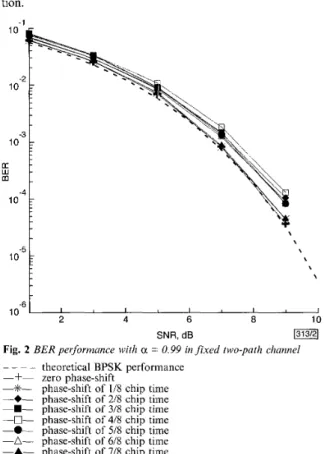
SNR, dBFig. 2 BER performance with a = 0.99 in fixed two-path chunnel
_ _ - _
-+-
-*-
-+-
-.-
-0- -0- -A- -A- theoretical BPSK performance zero phase-shiftphase-shift of I18 chip time phase-shift of 218 chip ti:me phase-shift of 3/8 chip tiime phase-shift of 418 chip time phase-shift of 518 chip ti:me phase-shift of 618 chip time phase-shift of 718 chip time
Simulation results: To evaluate the performance of the proposed RAKE receiver, computer simulations were carried out under dif- ferent channel conditions. The binary phase-shift keying (BPSK) DS-SS modulation scheme at a data rate of 16kbitk was assumed. The length of the PN code is 255. The roll-off factor of the squared root raised cosine filters at the transmitter and the receiver was set to 0.22. A two-path channel at a carrier frequency of 2GHz is assumed and the two paths assumed to have equal power. The delay between the two paths was set to an integer mul- tiple of the chip time. We restricted the pilot power to 10% of the total transmission power, i.e. 1.he pilot power gain Gp relative to the data power was set to -7.5dB, assuming there are 50 channels with 100% activity and all channels are of equal power. In the multipath searcher, the number M of the selected paths was set to
8 and the threshold 0 was set to 8dB below the peak power value of the M selected paths. The search period Tseorch was set to l0N; T,. In the channel sounding subsystem, the maximal number L1 of the finally selected paths was set to 4.
To investigate the effect of the sampling phase-shifts on the per- formance of our RAKE receiver, we simulated at eight different sampling phase-shifts. Fig. 2 shows the bit error rate (BER) per- formance with a = 0.99 in a fuced two-path channel. From Fig. 2,
we observe that the RAKE receiver with a zero (ideal) sampling phase-shift achieves almost the same performance as the theoreti- cal BPSK performance. For all the other sampling phase-shifts,
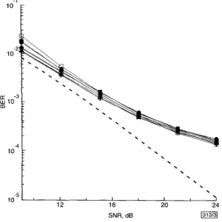
the performance degradation of the RAKE receiver is < 1dB in signal-to-noise ratio (SNR). Fig. 3 shows the BER performance with a = 0.5 in a two-path Rayleigh fading channel at a vehicle speed of 120km/h. From Fig. 3, we observe that the RAKE receiver performs almost the same with different sampling phase- shifts. Contrasted with the theoretical BPSK performance [3], the performance degradation of the RAKE receiver is -2dB in SNR at a BER of 1W. 1 -2 10
-
t
10 -4i
. .
\.
-5 12 16 20 24 10 SNR, d 6Fig. 3 BER performance with a = 0.5 in two-path Rayleigh fading
channel at vehicle speed of 120km/h
_ _ _ _ theoretical BPSK performance
-+-
zero phase-shift-*-
phase-shift of 118 chip time-+-
phase-shift of 2/8 chip time-.-
phase-shift of 3/8 chip time -0- phase-shift of 4/8 chip time -0- phase-shift of 518 chip time -A- phase-shift of 6 / 8 chip time -A- phase-shift of 7/8 chip timeConclusions: In this Letter, a fast feedfonvard channel sounding RAKE receiver is presented. Instead of utilising a conventional tracking loop, we use a novel path selection technique to cope with the rapid changes of the channel impulse response. In addi- tion, chip rate sampling can be used to reduce the hardware com- plexity of the RAKE receiver. Simulation results show that this RAKE receiver works well in a multipath fading channel even when a non-ideal sampling phase-shift occurs.
0 IEE 2000
Electronics Letters Online No: 20001187 DOI: 10.1049/el:20001187
Chun-Chyuan Chen and Chia-Chi Huang (Wireless communication Laboratory, Department of Communication Engineering. National Chiao-Tung University, 1001 Ta Hsueh Road, Hsinchu, Taiwan, Republic of China)
E-mail: [email protected]
27 July 2000
References
1 TURIN, G.L.: ‘Introduction to spread spectrum antimultipath techniques and their application to urban digital radio’, Proc. ZEEE, 1980, 68, (3), pp. 328-353
BRAUN, w.R.: ‘PN acquisition and tracking performance in DSI CDMA systems with symbol-length spreading sequences’, ZEEE
Trai7s. Commun., 1997, 45, (12), pp. 1595-1601
GLISIC, s., and VUCETIC, B.: ‘Spread spectrum CDMA systems for wireless communications’ (Artech House, Boston, 1997), pp. 236- 240
2
3
ELECTRONICS LETTERS 28th September 2000 Vol.
First-order and conditional statistics of rain
attenuation fade slope
B.C. Gremont and D.L. Ndzi
In accordance with the assumptions of Maseng and Bakken, the distribution of rain fade slope on high frequency GSO links is calculated and its Cauchy approximation is presented. The conditional PDF of the fade slope is finally modelled for application to predictive rain fade mitigation techniques (FMTs).
Theoretical model and its approximation: This Letter attempts to justify theoretically recent results published in [l, 21. The rate of change of rain attenuation, s(t), encountered on satellite slant
paths is commonly referred to as the fade slope, [l], and may be defined by
s ( t ) = [Y(t
+
At)-
Y(t)l/At (1) The slope is a function of two rain attenuation samples, y ( t+
At)and y(t). Rain attenuation is commonly sampled at 1 Hz, thus if At = 1 [second] one may refer to the instantaneous fade slope. Since the marginal statistics of attenuation is widely accepted as lognor- mal, it is logical that the distribution of y(t
+
At) and y ( t ) is joint- lognormal i.e.According to the assumptions of the Maseng-Bakken model [3, 41, the two parameters (wt, 0) define the statistics of rain atten-
uation on a satellite slant-path. It can be shown that the correla- tion factor in eqn. 2 is r = [P2E-P1’1-1]/[@2-1], where
p
describes the dynamic properties of rain attenuation. In this Letter, all the results were obtained for (m, 0) = (-1.4, 1.498) andp
= 1.65 x lk3. If we let w(t) = y ( t+
At), then it can be shown that the joint PDF of s(t) and w(t) is (omitting the dependence on t):- 2r(ln(y - A t . s ) - m)(lny - m) (Iny - ~ 2 ) ~
U2 + U2
(3)
The PDF of the fade slope, s E 1 4 3 , -[, can be obtained by inte-
grating eqn. 3 over all possible y , giving
+
m ) 2 ) ] dy 2r(ln(y - A t . s ) - m)(ln y - m )U2
-
(4) Fig. 1 shows the CDF (integral of eqn. 4) of the fade slope, which is compared to the output of a DSP rain synthesiser ([6]). The results show that there is a very good agreement. It is worth men- tioning that a very good (and simpler) approximation to the inte- gral of eqn. 4 is a Cauchy distribution given by
1 1
2 T
F ( s ) = Prob{s
5
s} = -+
- . arctan(K . s )where K is an empirical constant which will depend on the actual
values of m, 0,
p
(i.e. on the particular location of the link). Forour values, the best fit (obtained by a parametric search) is K =
37.7, in which case the CDF in eqn. 5 is virtually indistinguishable
from those obtained either by simulation or from eqn. 4, see Fig. 1. The conditional PDF f(s1y) is of practical interest to pre-
36 No. 20