This article was downloaded by: [National Chiao Tung University 國立交通大學] On: 27 April 2014, At: 20:21
Publisher: Taylor & Francis
Informa Ltd Registered in England and Wales Registered Number: 1072954 Registered office: Mortimer House, 37-41 Mortimer Street, London W1T 3JH, UK
Journal of the Chinese Institute of Engineers
Publication details, including instructions for authors and subscription information:
http://www.tandfonline.com/loi/tcie20
A combination logic design for a high speed IEEE
802.11 MAC controller
Ren‐Zong Li a , Shang‐Pin Huang b , Fu‐Shung Lin c , Ming‐Tsung Hong d & Po‐Ning Chen e a
Trans. Wireless Technology Laboratories , National Chiao Tung University , Hsin Chu, Taiwan 300, R.O.C. Phone: 886–3–5712121 ext. 52947 Fax: 886–3–5712121 ext. 52947 E-mail:
b
Trans. Wireless Technology Laboratories , National Chiao Tung University , Hsin Chu, Taiwan 300, R.O.C.
c
Macronix International Co., Ltd. , Taiwan 300, R.O.C. d
VXIS Technology Corporation , Taiwan 300, R.O.C. e
Department of Communications Engineering , National Chiao Tung University , Hsin Chu, Taiwan 300, R.O.C.
Published online: 03 Mar 2011.
To cite this article: Ren‐Zong Li , Shang‐Pin Huang , Fu‐Shung Lin , Ming‐Tsung Hong & Po‐Ning Chen (2003) A combination
logic design for a high speed IEEE 802.11 MAC controller, Journal of the Chinese Institute of Engineers, 26:2, 255-259, DOI:
10.1080/02533839.2003.9670777
To link to this article: http://dx.doi.org/10.1080/02533839.2003.9670777
PLEASE SCROLL DOWN FOR ARTICLE
Taylor & Francis makes every effort to ensure the accuracy of all the information (the “Content”) contained in the publications on our platform. However, Taylor & Francis, our agents, and our licensors make no
representations or warranties whatsoever as to the accuracy, completeness, or suitability for any purpose of the Content. Any opinions and views expressed in this publication are the opinions and views of the authors, and are not the views of or endorsed by Taylor & Francis. The accuracy of the Content should not be relied upon and should be independently verified with primary sources of information. Taylor and Francis shall not be liable for any losses, actions, claims, proceedings, demands, costs, expenses, damages, and other liabilities whatsoever or howsoever caused arising directly or indirectly in connection with, in relation to or arising out of the use of the Content.
This article may be used for research, teaching, and private study purposes. Any substantial or systematic reproduction, redistribution, reselling, loan, sub-licensing, systematic supply, or distribution in any
form to anyone is expressly forbidden. Terms & Conditions of access and use can be found at http:// www.tandfonline.com/page/terms-and-conditions
Short Paper
A COMBINATION LOGIC DESIGN FOR A HIGH SPEED IEEE
802.11 MAC CONTROLLER
Ren-Zong Li*, Shang-Pin Huang, Fu-Shung Lin, Ming-Tsung Hong, and Po-Ning Chen
ABSTRACT
In this paper, we propose a pure combinational logic design for the implementa-tion of IEEE802.11 Medium Access Control (MAC) protocol, in contrast to firmware implementation based on an embedded micro-engine. In order to have a timely response, a Control Frame Handler is also included in our MAC controller. A further improvement for timely manipulation on the time-critical management frames (such as Beacon, ATIM and Probe Response) is subsequently developed in our revised edition. Equipped with a self-developed PCMCIA unit, the functions of our MAC controller have been verified using two Altera EPF 10K-100 ARC240-2 FPGAs in an on-line MAC-to-MAC data exchange fashion. Experimental results show that a pure combinational logic design can easily achieve a baseband-interfacing throughput of over-100Mbps with a cost-effect gate count of 21702.
Key Words: IEEE 802.11, medium access control, wireless local area network.
*Corresponding author. (Tel: 886-3-5712121 ext. 52947; Fax: 886-3-5731663; Email: [email protected])
R. Z. Li and S. P. Huang are with the Trans. Wireless Technol-ogy Laboratories, National Chiao Tung University, Hsin Chu, Tai-wan 300, R.O.C.
F. S. Lin is with the Macronix International Co., Ltd., Taiwan 300, R.O.C.
M. T. Hong is with the VXIS Technology Corporation, Taiwan 300, R.O.C.
P. N. Chen is with the Department of Communications Engineering, National Chiao Tung University, Hsin Chu, Taiwan 300, R.O.C.
I. INTRODUCTION
The current implementations of IEEE 802.11 Medium Access Control (MAC) mostly incorporate a CPU core in their integrated circuit designs, where the MAC protocol is realized through firmware implementation. Two renowned examples are the AMD79C30 and HFA3842 MAC controllers. The former employs an embedded 80188 core, while the latter incorporates a micro-programmed MAC engine. As the IEEE 802.11 MAC standard (1999) converges to DFW CSMA/CA, and no further revision on the underlying MAC standard is in process, the need for
flexibility and customization of the MAC design has gradually shifted to the demand for a cost-effective design, i.e., a design that can achieve high speed at a fairly low cost. This motivated us to develop a pure combinational-logic-based MAC controller.
Different from the Ethernet standard, the MAC specified in IEEE 802.11 requires more manage-ment efforts (in addition to the basic CSMA/CA mechanism) due to the unreliable nature of wireless transmissions. The ability to handle the control frames and the management frames are therefore es-sential to an IEEE 802.11 MAC controller. Perhaps, this is the key reason why the firmware-based imple-mentation approach is more prevalent on the market. For example, a timely layer-2 acknowledgement and re-transmission due to previous transmission failure are specified in the standard. To fulfill the manage-ment requiremanage-ment, a separate Control Frame Handler circuit is designed to manipulate the timely transmis-sion and response of the control frames, such as RTS, CTS and ACK frames. This unit closely co-works with other units under the finite-state machine on which our design is based, and complements the man-agement functionality of IEEE 802.11. A second re-vision of our MAC verilog code additionally includes
256 Journal of the Chinese Institute of Engineers, Vol. 26, No. 2 (2003)
the manipulation of time-critical management frames (which was previously designed to be handled by the host driver) to further enhance the system perfor-mance.
Our experimental design was carried out in two stages, which yielded two versions of MAC verilog codes. In the first stage, we only attempted to sub-stantiate the idea of realizing the IEEE 802.11 MAC protocol using pure combinational logic, and only targeted the 1/2 Mbps basic processing speed of IEEE 802.11 MAC (Hong 1999; Lin, 1999). After its theo-retical effectiveness was shown, a major revision of the previous version subsequently proceeded, which resulted in an over-100 Mbps data rate to-and-from the baseband processor (Huang, 2000). Although the current standard only specifies up to 54 Mbps nomi-nal data rate (IEEE std. 802.11a, 1999), our experi-mental implementation does confirm the feasibility and cost-effectiveness of a combinational logic de-sign of an IEEE 802.11 MAC.
It is worth mentioning that a pure combinational logic design of IEEE 802.11 MAC also facilitates the chip-level integration with the baseband processor, as we have done in our joint project with the baseband team. Since both the MAC and the baseband circuits are implemented directly using the verilog language, a cell-level joint-simulation can be readily performed in an on-line transceiving fashion, which largely en-sures the workability of an integrated MAC/baseband processor.
II. BASIC DESIGN OF THE MAC CONTROLLER
1. General Description on MAC Controller Design
In the first trial, only the compulsory distribu-tion coordinadistribu-tion funcdistribu-tion (DCF) scheme over ad hoc topology was implemented. The supports to the op-tional point coordination function (PCF) scheme as well as the infrastructure topology were added in the revised version described in the next section.
The basic CSMA/CA mechanism relies on the CCA (clear channel assessment) signal reported by the baseband processor. The CCA signal is effective only when the NAV (Net Allocation Vector) timer, loaded from the 16-bit Duration Field of the frames from other stations, is expired. This prevents the cur-rent station from intervening in the data exchanges o f o t h e r s t a t i o n s . U p o n t h e n e e d f o r f r a m e transmission, a number that is uniformly selected from an exponentially increasing contention window (CW) is loaded into the backoff timer at the first time CCA indicates a clear medium. This timer counts down only when the channel is clear (i.e., CCA = 0). As the timer reduces to zero, the queued frame is
transmitted if the medium is again sensed clear. The DCF also employs different time offsets to prioritize the transmitted frames. In general, control frames, such as RTS, CTS and ACK, should have higher priority for medium usage than the normal data/management frames. Accordingly, a longer
Distributed Inter-Frame Space (DIFS) offset is added
before the execution of the contention procedure for the data/management frames.
In addition to the backoff timer and IFS timer, an ACK timer is used to monitor the status of the pre-vious transmission procedure. Its expiration indicates the occurrence of a failure transmission, and a retrans-mission may need to be scheduled. For ease of implementation, these three timers were separately designed in our first MAC version. We, however, found that these three timers indeed take turns to be effective. In other words, only one of the three tim-ers counts at a time, and the othtim-ers always remain idle before the expiration of the currently effective timer. Consequently, in our second edition, they share the same counter circuitry.
Another timer necessary for the MAC control-ler is the Timing Synchronous function (TSF) timer, which is used to synchronize the procedures for all stations in a basic service set (BSS). It needs to be periodically adjusted according to the recent Beacon frame, contentionally transmitted by one of the sta-tions in an ad hoc BSS.
The RTS/CTS frame exchange procedure is used to improve the system throughput under the occur-rence of hidden nodes. The procedure should be used only when the length of the transmitted frame is greater than the RTS threshold. Our design substan-tiates that this procedure can be handled by the MAC controller without the intervention of the host driver. According to the standard, only the first frag-ment of an MSDU (MAC Service Data Unit) is re-quired to execute the CSMA/CA mechanism and RTS/ CTS frame exchange procedure; the remaining frag-ments can be transmitted directly within the SIFS time interval. This is used to uphold the integrity of an MSDU for higher layer protocol stack.
2. T r a n s m i s s i o n a n d R e c e p t i o n F i n i t e S t a t e Machine
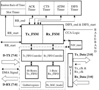
In Fig. 1, where the function diagram of our MAC controller is depicted, the transmission finite state machine (Tx_FSM) implements the DCF and provides necessary interfacing signals to the baseband processor.
Contrary to the Tx_FSM, the Reception FSM processes the received frame based on the infor-mation extracted from its header. It should tell apart the data frames from the control frames and
management frames, and pass the information to the Tx_FSM to take the proper response. Also examined in this unit is the CRC16 for PLCP header, the proto-col version and the uni/multicastness of Address Field 1 (i.e., the destination MAC address). In case an er-ror occurs during these examinations, the reception process as well as the received frame is aborted. At last, a proper status will be placed in the status register, followed by an interrupt to the host driver. The host driver then reads the status register to de-termine whether a frame is successfully received.
3. Timer Design
In this version, the counters for each timer are separately designed, and run at 44MHz. The IFS timer employs a 12-bit counter, also ticking based on the 44MHz system clock. The ACK timer for MAC-level acknowledgement should measure the transmission
time of an ACK frame plus additional 10 µs, which
depend on the Signal Field of the PLCP header of the frame being acknowledged. In case the ACK timer expires before the reception of an ACK, an interrupt is issued to the host driver to indicate the failure of previous transmission. The CTS timer is designed similarly to the ACK timer except that it measures the anticipated return time of a CTS frame upon the transmission of an RTS frame. The ATIM timer is used when the station is in an ad hoc network.
The NAV timer is used to carry out the virtual carrier sense scheme. Its initial value is equal to the Duration Field of the received frame in milliseconds. In our design, the countdown process begins after the reception of the last byte of a frame from the baseband processor. Its update is performed when the
Duration Field of a newly received frame is greater than the current NAV value.
4. FIFO Controller
The Tx/Rx_FIFO controller in Fig. 1 acts as a data flow arbitrator. It either derives from the baseband processor to the external SRAM for reception, or reads from the external SRAM to the baseband processor for transmission. Both directions follow the 4-bit-wide MII interface, and result in a reduction of the transmission/reception clocks to 250/ 500 KHz respectively for 1/2 Mbps data rates. Addi-tional implicit signal is implemented to differentiate the current 4-bit input between the least- and most-significant 4 bits. The Tx_FIFO is 48-byte wide, a length to sufficiently store the entire frame header. Since a large FIFO consumes a lot of gate counts, an alternative design has been used in our revision. The Rx_FIFO is only one byte in length, which is suffi-cient due to the fact that the reception clock is much slower than the SRAM access clock.
5. Bus Interface Unit (BIU) and Data Storage on External SRAM
The bus interface to the host computer follows the PCMCIA 2.01 standard (1992). As the PCMCIA unit is designed solely for on-board verification of the MAC controller, we fix the I/O port addresses to be 280H, 281H and 282H.
The external SRAM is presumed to be 32K×8
in size. In our first trial design, a fixed partition on the external SRAM is adopted for design convenience, where each partition is 2.5 Kbytes in size, which is much larger than 2346 bytes-the largest possible
for an IEEE 802.11 data frame. As shown in Fig. 2,
two 2.5K byte partition units are respectively dedi-cated to the transmission of data and management
Random Back-off Timer
Slot Timer ACK Timer RB_end RB_start RB_start CCA Logic B A S E B A N D M I I
DIFS_end & DIFS_start
DMA Signal D-TX [7:0] Tx_Data [3:0] Tx_clk & Rx_clk Rx_Data [3:0] D-RX [7:0] Tx_FIFO Controller Grabbed registers 48-Bytes Tx_FIFO 1-Byte Rx_FIFO Rx_MAC_header NAV_timer Rx_FIFO Controller Tx_FSM Rx_FSM CTS Timer ATIM Timer DIFS Timer
Fig. 1 Architecture of MAC controller
0000H 09c4H 1388H 1d4cH 61a8H 6b6cH MAX 2346 bytes MAX 256 bytes MAC 256 bytes
MAX 2346 bytes/Per frame Data Transmission Part (2 units) Reception Part (10 units) Magm Magm Data (9 units)
Fig. 2 Storage architecture for external SRAM
258 Journal of the Chinese Institute of Engineers, Vol. 26, No. 2 (2003)
frames. Nine and one fixed-sized partition units are reserved respectively for the reception of data and management frames. In our design, the management frames, owing to their nature, have higher priority than the normal data frames.
6. CRC Check and Gate Count Summary
A CRC unit is designed to perform the genera-tion of transmission CRC32 and the examinagenera-tion of reception CRC32. To adapt to the 4-bit MII interfaces, a parallel CRC architecture is implemented (Pei, 1992). As anticipated, a failure in reception CRC32 check will ignite the deletion of the received frame.
The resultant gate counts for ASIC-implemen-tation and FPGA-implemenASIC-implemen-tation are respectively 27, 000 gates (Synopsys) and 4600 logic cells & 1500 flip-flops.
III. ADVANCED DESIGN OF THE MAC CONTROLLER
After the success of trial combinational logic design, we proceed to work on its refinement. Simu-lations on the previous version only provide us with a half-duplex processing speed of 9 Mbps due to some critical path delays. Other critical issues in the pre-vious design are (1) stick to 44MHz system clock; (2) inefficient use of external SRAM; (3) large gate counts due to the usage of big FIFOs; (4) no control of time-critical management frames; (5) no support to PCF; and (6) no support to infrastructure topology. These issues are resolved in the new MAC edition.
As illustrated in Fig. 3, the new design actually follows the basic structure of the previous design. The baseband interface becomes serial (instead of 4-bit-wide MII parallel interface) in order to comply with commercialized basedband processors such as
HFA3861.
The ESI (external SRAM interface) handles data access to-and-from the PCMCIA HIU (Host interface unit), RxFIFO, TxFIFO and the external SRAM. It arbitrates the data flows of (1) SRAM to host through PCMCIA HIU, (2) host to SRAM through PCMCIA HIU, (3) SRAM to TxFIFO, and (4) RxFIFO to SRAM. The latter two flows have higher priority than the former two. The external SRAM interface now addresses up to 64K(8 to fulfill the buffer need of an access point (AP). To efficiently use the memory space, the received frames are now consecutively stored in the external SRAM, and an indirect and transparent access scheme for the host to the SRAM is implemented. Part of the SRAM space is reserved for the storage of Beacon frame, which is periodi-cally and automatiperiodi-cally transmitted by the MAC con-troller if the station acts as an AP. The synchroniza-tion of the TSF timer is now self-updated and main-tained by the MAC controller. The host driver (of an AP) can update the content of the Beacon frame when-ever necessary.
Due to an effort to synchronize the SRAM ac-cess with the baseband transmission, the TxFIFO now only employs a 32-bit register. Also by a complete clock synchronizing design, the MAC controller now adapt to various system clocks, ranged from 11 MHz to 44 MHz. Three management frames, i.e., Beacon, ATIM and Probe Response, are handled without the intervention of the host driver. This can further ease the burden on a host driver.
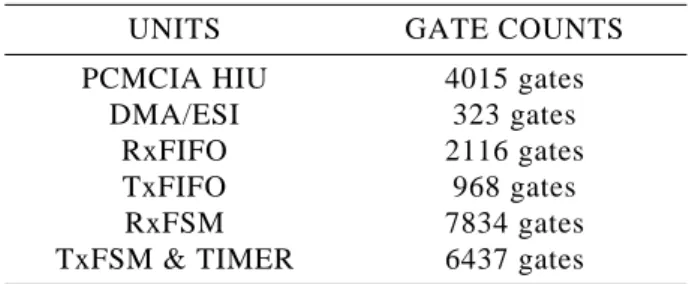
As aforementioned, the backoff timer, the IFS timer and the ACK/CTS timer now share the same counter so that further reduction of gate counts is rendered. The support to PCF is achieved by a flex-ible disability of the CSMA/CA mechanism through a register configuration. The resultant gate count for each unit is listed in Table 1.
IV. SYSTEM VERIFICATIONS
The verification and testing of a protocol pro-cessor is a significant part of its development. As our target is a hardware MAC controller, the first
Fig. 3 Architecture of the MAC controller (revised version)
Table 1 Gate counts for each unit of the MAC controller (revised version)
UNITS GATE COUNTS
PCMCIA HIU 4015 gates
DMA/ESI 323 gates
RxFIFO 2116 gates
TxFIFO 968 gates
RxFSM 7834 gates
TxFSM & TIMER 6437 gates
HOST COMPUTER PCMCIA HIU BASEBAND MODULE TIMER ESI MAC SRAM 32K×8 TxFSM TxFIFO RxFSM RxFIFO
verification was straightforwardly performed using the Verilog XL simulator. In short, we began the validation of our RTL (Register Transition Level) code through a few test benches, including CSMA/ CA, RTS/CTS and ACK mechanisms, under the Verilog XL simulator. We then performed the simu-lations based on up to five copies of our MAC mod-ule to double-confirm that they do follow the CSMA/ CA mechanism while exchanging data. Our next step was to transfer the RTL code to its Gate Level
coun-terpart (in terms of CIC 0.35 µm cell library), and
conducted the above simulations again. In this grada-tion, we also examined the circuit characteristics, such as its adaptation to different system clocks. The simu-lation result showed that our design could truly achieve a baseband-interfacing throughput of 100Mbps for any system clock between 11 MHz and 44 MHz. In order to further ensure the feasibility of our design, we transformed our RTL code onto Altera EPF 10K-100 ARC 240-2 FPGA mounted at a self-designed PCMCIA adapter; then a test platform with two notebooks, each equipped with our PCMCIA adapter, was set up for a real MAC-to-MAC transceiv-ing test. Since some of the MAC functionalities must be ignited by the baseband processor such as CCA signaling, another FPGA module was designed and placed on a separate board to emulate the in-between baseband processors. Through the FPGA test, we got a measure of 120 Kbytes FTP (File Transfer Protocol) throughput between the two Linux-based notebook computers. The above procedure was in fact made systematic after each revision of our code.
V. CONCLUSIONS
In this paper, we present a pure combinational logic design for the IEEE 802.11 MAC controller. Various design issues are located and resolved dur-ing the development. Through its realization, we con-cluded that the IEEE 802.11 MAC, although seem-ingly complicated, is not only hardware feasible, but can be realized simply by around twenty thousand gates. In addition, a pure combinational logic design, as anticipated, can easily achieve the data rate of 100 Mbps, and further improvement is indeed promising. Some design considerations of ours may also serve as guides to those who are interested in such a realiza-tion, such as (1) robust adaptation to various system
clocks; (2) on-chip hardware reply and generation for control frames and time-sensitive management frames; (3) efficient usage of storage and access prioritization. Also observed is that although sev-eral timers are specified in the standard, only one timer is necessary to count at a time, which may a little simplifying the logic circuits.
ACKNOWLEDGMENT
The work was sponsored jointly by the Minis-try of Education and National Science Council, ROC, under the Contact: 89-E-FA06-2-4.
REFERENCES
Hong, M. T., 1999, “Design and Implementation of IEEE 802.11 MAC Controller,” Master Thesis, Institute of Communications Engineering, Na-tional Chiao Tung University, Hsin Chu, Taiwan, R.O.C.
Huang, S. P., 2000, “Design and Implementation of High Speed IEEE 802.11 MAC Controller,”
Mas-ter Thesis, Institute of Communications
Engineer-ing, National Chiao Tung University, Hsin Chu, Taiwan, R.O.C.
IEEE Std. 802.11, 1999, Wireless LAN Medium
Ac-cess Control (MAC) and Physical Layer (PHY) Specifications.
IEEE Std. 802.11a, 1999, High-Speed Physical Layer
in the 5GHz Band.
IEEE Std. 802.11b, 1999, Higher-Speed Physical
Layer Extension in the 2.4 GHz Band.
Lin, F. S., 1999, “Design and Implementation of IEEE 8 0 2 . 1 1 M A C C o n t r o l l e r : T r a n s m i t t e r Part,” Master Thesis, Institute of Communications Engineering, National Chiao Tung University, Hsin Chu, Taiwan, R.O.C.
PCMCIA, 1992, “PCMCIA PC Card Standard,” Re-lease 2.01, Section 4: Card Interface.
Pei, T. B., and Zukowski, C., 1992, “High-speed Par-allel CRC Circuits in VLSI,” IEEE Transaction
on Communication, Vol. 40, No. 4, pp. 653-657.
Manuscript Received: Jul. 18, 2001 Revision Received: May 02, 2002 and Accepted: Jun. 10, 2002