Demonstration of Using Digital FIR Filter and Matched Filter to
Increase Data Rate in Visible Light Communication
Yu-Feng Liu
a, Chien-Hung Yeh
b,c, Chi-Wai Chow
a, Po-Yen Huang
a, and Yang Liu
d aDepartment of Photonics and Institute of Electro-Optical Engineering, National Chiao Tung
University, Hsinchu 30010, Taiwan
b
Information and Communications Research Laboratories, Industrial Technology Research Institute
(ITRI), Hsinchu 31040, Taiwan
c
Graduate Institute of Applied Science and Engineering, Fu Jen Catholic University, New Taipei
24205, Taiwan
d
Hong Kong Productivity Council (HKPC), Hong Kong
ABSTRACT
Using digital-filters in time domain are demonstrated to enhance the modulation-speed of 1 MHz bandwidth white LED communication. Digital FIR filter and matched filtering are used to reduce the inter-symbol-interference (ISI). Hence, 20-Mbps is achieved by using 4-ASK modulation.
Keywords: Wireless, Visible Light Communication, Light emitting diode (LED), 4-ASK, Finite Impulse Response (FIR)
filter, Matched Filter, Equalization.
1. INTRODUCTION
Visible light communication (VLC) using white light emitting diode (LED) prevents electromagnetic-interference and provides license free and high signal-to-noise ratio (SNR) link with security. These characteristics of VLC make it useful in the application of wireless communication in hospital and aircrafts where the radio waves are not allowed. The integration of VLC into lighting infrastructure also makes it energy-efficient, and the intensity is sufficient large as well as safe for human eyes.
Different system configurations of VLC were explored in 1–8. In order to expand the available bandwidth for the VLC LED transmission, different techniques such as optical blue-filtering1, multiple-resonant equalization2, post-equalization3,
and discrete-multi-tone (DMT) modulation5 may be used. Without using blue filtering, the 3dB-frequency for VLC
system is limited to a few MHz4 by the slow responding light emission from the yellow phosphor.
In this work, we proposed a visible light communication using 4-level amplitude-shift keying (4-ASK) with digital filtering. The mathematical form of filters at transmitter (Tx) and receiver (Rx) is analyzed with the requirement of reducing inter-symbol interference. To transmit signal in a limited bandwidth, the Nyquist’s first criterion of reducing ISI is considered. The filter at Rx has to match the response of the filter at Tx to maximize the signal to noise ratio (SNR). The choice in our experiment is two square root raised cosine (SRRC) filters at Tx and Rx. In addition to the consideration of filter design for reducing ISI and noise, the channel impulse response has to be equalized. This response is cancelled by using zero-forcing equalizer at transmitter. The experimental result matches the prediction of theoretical analysis.
Our previous experiment shows that using simple pre-distortion and post-equalization schemes, 10 Mbps binary amplitude-shift-keying (ASK) is achieved with a significant improvement in signal quality4 by using a commercially
available 1.28 MHz modulation bandwidth white-light phosphor-based LED. No optical blue filter is used to improve the frequency response of the LED; without losing too much the optical energy, a transmission distance of 1 m can be achieved6. In this work, we proposed and experimentally demonstrated the use of digital filtering (using adaptive
controlled FIR filter at the transmitter (Tx) side and a pair of SRRC filters at the receiver (Rx) side and Tx side) and 4-ASK to further double the data rate (from 10 Mbps to 20 Mbps) also without optical blue filtering. 20 Mbps with bit-error-rate (BER) 10-10 was achieved with a transmission distance of 1 m.
Broadband Access Communication Technologies VII, edited by Benjamin B. Dingel, Raj Jain, Katsutoshi Tsukamoto, Proc. of SPIE Vol. 8645, 86450N · © 2013 SPIE · CCC code: 0277-786X/13/$18 · doi: 10.1117/12.2002241
Proc. of SPIE Vol. 8645 86450N-1
2. EXPERIMENTS AND MEASUREMENT METHOD
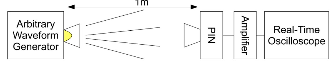
Fig. 1 shows the VLC experimental platform. The white-light LED used in the experiment is obtained from Cree (XLamp XR-E LED) and it was modulated by an arbitrary waveform generator (Agilent 33220A). The white-light emitted from the LED is transmitted across 1 m of free space, and then received by a silicon-based PIN Rx (Thorlabs PDA36A) which has a bandwidth of 17 MHz. A pair of lens at the Tx and Rx are used for focusing. The received signal was then amplified by a wideband coaxial amplifier (Mini-Circuit ZHL-6A), and the electrical signal is recorded by a real-time oscilloscope (Tektronix TDS2022B). The whole physical transmission subsystem described above is represented by the “Communication channel” in Fig. 2 which contains the digital signal flow from Tx to Rx. The information is first mapped from binary sequence to 4-ASK symbol, and the resultant waveform is filtered by using adaptively controlled FIR filter which is a 12-taps time domain zero-forcing equalizer.
Arbitrary
Waveform
Generator
Real-Time
Oscilloscope
PI
N
Am
plifie
r
1m
Fig. 1. Experiment setup of the VLC LED communication.Binary Sequence
4-level Mapping
Up-Sampling
Zero-Forcing
Equalizer
SRRC filter
SRRC filter
Communication
Channel
Error Analysis
Fig. 2. Digital signal flow of the proposed system.
A pair of SRRC filters with roll-off factor equal to 0.25 is used before AWG and after real-time oscilloscope, as shown in Fig 2. These two SRRC filters are capable of shrinking the signal spectrum while maintaining very low inter-symbol-interference (ISI), so it is suitable to be applied in this band-limited communication system. The pseudo random binary sequence (PRBS) was mapped to the 4-level ASK symbols. We proposed to use a symbol rate of 10M symbol/s, and by using the matched filter, the signal spectrum was band-limited in 10MHz. Instead of using multiple-resonant equalization circuits, the channel capacity is enhanced by using digital filters on a single LED without using optical blue filter.
3. CHANNEL RESPONSE AND DIGITAL FILTERING DESIGN
3.1 Channel response model and measurement
The electrical-optical-electrical of the VLC system is modeled as an input and output relation as:
)
(
)
(
*
)
(
)
(
x
x
t
h
t
n
t
y
=
+
(1)Proc. of SPIE Vol. 8645 86450N-2
x(t) is the input electrical signal, y(t) is the output electrical signal, h(t) is the channel impulse response, and n(t) is a band-limited additive white Gaussian noise. To analyze the channel in frequency domain, the Fourier transform of equation (1) is expressed as:
)
(
)
(
)
(
)
(
f
X
f
H
f
N
f
Y
=
+
(2)The Y(f), X(f), H(f) and N(f) represents the Fourier Transform of y(t), x(t), h(t) and n(t).
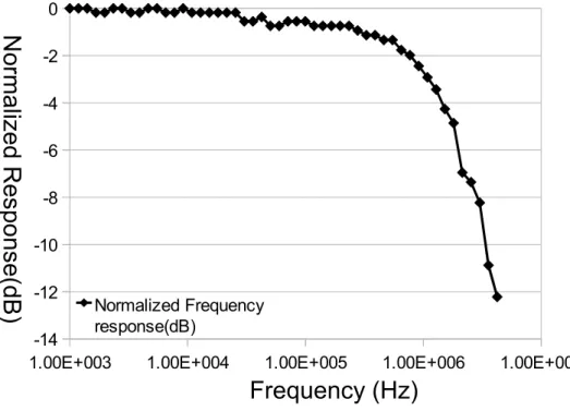
The relative amplitude response of frequency response |H(f)| is measured, as shown in Fig. 3. The E-O-E channel has a low-pass transfer function that limits high frequency component, and the 3-dB bandwidth of the system is about 1MHz. Thus in order to get better signal quality after transmission over the channel, the effect of frequency response and noise should be considered. The digital filters are used at both Tx and Rx side to generate an improved signal YD(f);
)
(
))
(
)
(
)
(
)
(
(
)
(
f
X
f
D
f
H
f
N
f
D
f
Y
D=
TX+
RX (3)1.00E+003 1.00E+004 1.00E+005 1.00E+006 1.00E+007 -14 -12 -10 -8 -6 -4 -2 0 Normalized Frequency response(dB)
Frequency (Hz)
No
rm
ali
zed
Re
sp
on
se(
d
B)
Fig. 3. Frequency response of VLC E-O-E channel.
3.2 Matched filter design for AWGN channel
First, we consider the case when channel response H(f) can be neglected. Equation (3) is rewritten as:
)
(
)
(
)
(
)
(
)
(
)
(
))
(
)
(
)
(
)
(
(
)
(
f
X
f
D
f
H
f
N
f
D
f
X
f
D
f
D
f
N
f
D
f
Y
D=
TX+
RX=
TX RX+
RX (4)Proc. of SPIE Vol. 8645 86450N-3
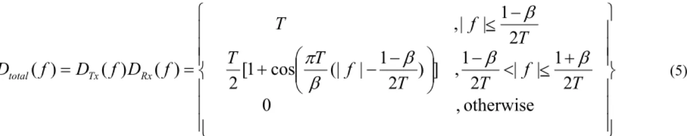
The “Nyquist’s First Criterion” is used for minimizing inter-symbol interference. This mathematical principle is described in [8]. The criterion requires the total transfer function in a specific form to reduce ISI. It is a common choice to use the following expression as the total transfer function:
⎪
⎪
⎪
⎭
⎪⎪
⎪
⎬
⎫
⎪
⎪
⎪
⎩
⎪⎪
⎪
⎨
⎧
+
<
<
−
⎟⎟
⎠
⎞
⎜⎜
⎝
⎛
−
−
+
−
<
=
=
otherwise
,
0
2
1
|
|
2
1
,
]
)
2
1
|
(|
cos
1
[
2
2
1
|
|,
)
(
)
(
)
(
T
f
T
T
f
T
T
T
f
T
f
D
f
D
f
D
total Tx Rxβ
β
β
β
π
β
(5)T is the symbol duration. β is roll-off factor which controls the spectral width. The plot for of Dtotal (f) is show in Fig.
4. -1 -0.8 -0.6 -0.4 -0.2 0 0.2 0.4 0.6 0.8 1 0 0.2 0.4 0.6 0.8 1
Frequency
Fu
n
ct
ion
V
al
u
e of
R
ai
sed
C
osi
n
e
Beta=0.01 Beta=0.25 Beta=0.5 Beta=0.75Fig. 4. Transfer function Dtotal (f) with different values of roll-off factor.
This distribution of Dtotal is raised cosine function. With this constraint, we can further find the expression of DTx and
DRx respectively. One of the solutions to this constraint is square root raised cosine filters (the response is the square-root
of raised cosine function), and the proposed system includes these two SRRC filters as shown in Fig. 2. The expression of filter design without channel response is expressed as:
)
(
)
(
)
(
f
D
f
D
f
D
SRRC total Rx SRRC Tx=
=
(6)These two filters are matched filters which enhance signal to noise ratio.
(1/T) Hz
Proc. of SPIE Vol. 8645 86450N-4
3.3 Cancellation of channel impulse response
In section 3.2, the channel response H( f ) is neglected, we need a corrected version of DTX to satisfy:
)
(
)
(
)
(
f
H
f
D
f
D
SRRC Tx Corrected Tx=
(7)Using zero-forcing equalizer, the digital filter design at Tx can be expressed as:
)
(
1
)
(
)
(
f
H
f
D
f
D
SRRC Tx Corrected Tx=
(8)The reciprocal of H(f) is the zero-forcing equalizer. The final design of digital filters at transmitter is the zero-forcing equalizer followed by SRRC filter, as expressed in (8). This analysis shows that our system can reduce the effect of ISI caused from limited bandwidth. Time domain expression of SRRC filter is represented as:
⎪
⎪
⎪
⎪
⎪
⎭
⎪
⎪
⎪
⎪
⎪
⎬
⎫
⎪
⎪
⎪
⎪
⎪
⎩
⎪
⎪
⎪
⎪
⎪
⎨
⎧
−
+
+
−
±
=
−
+
+
=
+
−
=
otherwise
Ts
t
Ts
t
Ts
t
Ts
t
Ts
t
Ts
t
t
t
h
,
]
)
4
(
1
[
)]
1
(
cos[
4
)]
1
(
sin[
4
,
)]
4
cos(
)
2
1
(
)
4
sin(
)
2
1
[(
2
0
,
4
1
)
(
2β
π
β
π
β
β
π
β
β
π
π
β
π
π
β
π
β
β
(9)By proper setting of filter truncation and delay, the filters are all implemented in time-domain in the experiment.
4. POST PROCESSING OF RECEIVED SIGNAL
The channel impulse response was first estimated by transmitting training symbols and using Fast Fourier Transform (FFT). The offline processing provides the calculated zero-forcing equalizer (ZFE) at Rx side (error analysis block in Fig. 2) which updated the FIR filter at Tx, and it was stable and converged in a few iterations. The BER over different
modulating depth was measured by analyzing a number of 11500 randomly transmitted symbols, which is shown in Fig. 5.
Proc. of SPIE Vol. 8645 86450N-5
get
Igo
11
-12 -10 -8 -6 -4 -2 0 0 0.5 1 1.5 Lo g( B E R )Modulating Peak-to-Peak Voltage (Volt)
Fig. 5. Bit error rate versus different peak-to-peak voltage at transmitter.
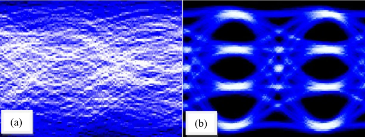
At modulating depth of 1.4V, the effect of FIR filter can be obviously seen in Fig 4. Without the FIR filter, the signal was corrupted by ISI as shown in Fig. 6(a). Using the FIR filter, the received 4-level eye-diagram is clear as seen in the Fig. 6(b). Without using optical blue filtering, and without using multiple-LEDs, the achieved data rate is close to 20 times of the 1MHz 3dB bandwidth.
Fig. 6. Measured eye-diagram (a) before applying FIR filter (b) after applying FIR filter.
5. CONCLUSION
In this work, the FIR filter is demonstrated in visible light communication link without using optical blue filter; compared with using multiple-resonant equalization, the single LED pre-equalization system is demonstrated to enhance transmission rate effectively in limited bandwidth without optical blue filtering. The achieved data rate (20Mbps) is higher than receiver bandwidth (17MHz) due to the fact that matched filters and 4-level ASK formats is spectral efficient. The principle of using SRRC filters and zero-forcing equalizer is analyzed. To reduce ISI, the raised cosine transfer function is chosen as total response of filters. The zero-forcing equalizer is used to compensate the channel response, so that the filters at Tx and Rx are matched to reach better SNR.
The results shows sufficient signal to noise ratio and thus the transmission distance and the data rate could be further increased with the error correction coding. In the experiment, the ZFE was estimated to be fixed over a long time.
Since the effect of in-door multi-path delay is not significant for the lower symbol rate7, if the property of yellow
phosphor for the transmitting LED is stable, the pre-equalizer could be calibrated once for a long time. Finally the
(a)
(b)
Proc. of SPIE Vol. 8645 86450N-6
equivalent mathematical form of the transmitter digital filtering scheme is a FIR filter, which can be elaborated with advanced algorithm, and operated with lower computational complexity compared with OFDM.
REFERENCES
[1] K.-D. Langer and J. Vučić, “Optical wireless indoor networks: recent implementation efforts,” European Conference on Optical Communication (ECOC), Paper We.6.B.1 (2010).
[2] Dominic C. O'Brien, Lubin Zeng, Hoa Le-Minh, Grahame Faulkner, Joachim W. Walewski, Sebastian Randel, “Visible light communications: Challenges and possibilities”, Proc. of PIMRC, 1-5 (2008).
[3] H. L. Minh, D. O'Brien, G. Faulkner, L. Zeng, K. Lee, D. Jung, Y. Oh, and E. T. Won, “100-Mb/s NRZ visible light communications using a postequalized white LED,” IEEE Photon. Technol. Lett., 21(15), 1063-1065 (2009).
[4] Y. F. Liu, Y. C. Chang, C. W. Chow, C. H. Yeh, “Equalization and pre-distorted schemes for increasing data rate in in-door visible light communication system,” Optical Fiber Communication Conference & Exposition (OFC), JWA083(2011).
[5] Jelena Vučić, Christoph Kottke, Stefan Nerreter, Klaus-Dieter Langer, and Joachim W. Walewski, “513 Mbit/s visible light communications link based on DMT-modulation of a white LED,” Journal of Lightwave Technology 28(24), 3512–3518(2010).
[6] C. W. Chow, C. H. Yeh, Y. F. Liu, Y. Liu, “Improved modulation speed of LED visible light communication system integrated to main electricity network”, IEE Elect. Lett. 47(15), 867-868(2011).
[7] Toshihiko Komine, Masao Nakagawa, “Fundamental analysis for visible-light communication system using LED Lights”, IEEE Trans. Consum. Electron. 50(1), 100-107(2004).
[8] J. G. Proakis and M. Salehi, [Digital Communications], McGraw-Hill, Chap. 9(2007)
Proc. of SPIE Vol. 8645 86450N-7