A Low-Cost GPS Satellite Signal Baseband System Using FPGA Prototyping
5
0
0
全文
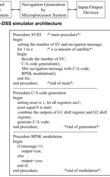
(2) RF Module. Four-Channel GPS-DSS Baseband System. D/A and A/D Converter. Navigation Generation by Microprocessor System. Input/Output Devices. Fig. 1. Four-channel GPS-DSS simulator architecture C/A Code Generator 32 PRN ID. G2 Phase Taps. BPSK Modulation Mixer. Mixer. Mixer. G2 Shift Register. Procedure SVID /* main procedure*/ begin setting the number of SV and navigation message; for 1 to n /* n is amount of satellite*/ begin decode the number of SV; C/A code generation(); Mix navigation message with C/A code; BPSK modulation(); end for; end procedure; /*end of main*/ -----------------------------------------------------------Procedure C/A code generation begin setting reset is 1, let all registers are1; reset equal 0 is start; combine the outputs of G1 shift register and G2 shift register; generate C/A code; end procedure; /*end of generation*/ -----------------------------------------------------------Procedure BPSK modulation begin if (message=1) output=cos; else output=-cos; end if; end procedure; /*end of modulation*/. Digital Baseband Signal. G1 Shift Register. Navigation Message from Microprocessor System. Cosine Wave. Fig. 2. Simplified four-channel GPS-DSS baseband system and control Phase-Locked-Loop (PLL) and RF circuitmajor use microwave passive components to implement. The multi-channel GPS simulator using traditional approach to design and implement was proposed in [6]. The [6] is purposed to generate different satellite baseband signal to estimate position correctness of the GPS receiver. Hence, if the system wants to set up four-channel then the system cost will be expensive. In our goal is to design a low-cost system. Therefore, we propose a new architecture of GPS-DSS baseband system which can satisfy the cost demand for GPS measure instrument.. 3: SYSTEM ARCHITECTURE OF FOURCHANNEL GPS SATELLITE SIGNAL BASEBAND SYSTEM. Fig. 3. The algorithm of simplified four-channel GPS-DSS baseband system. A four-channel GPS-DSS simulator architecture consists of GPD-DSS baseband systems, microprocessor system, input/output devices, A/D and D/A converter and RF module which are shown in Fig. 1. The GPSDSS baseband systems are adoption Time Division Multiple (TDM). The navigation message of GPS-DSS simulator is generated by microprocessor system. The function of GPS-DSS baseband system is to generate C/A code, mix navigation message with C/A code and module by Biphase-Shift Keying (BPSK) and implement using FPGA. The modulated navigation signal will be transmitted by RF modulation on L1 carrier. The GPS receiver will receive the pseudo GPS satellite signal for function testing and verification. The simplified four-channel GPS-DSS baseband system for GPS-DSS simulator is shown in Fig. 2. The simplified four-channel GPS-DSS baseband system consists of C/A Code Generator, Navigation Message, BPSK modulation and mixer. We reduce the FPGA resource usage in the four-channel GPS-DSS baseband system using IP reuse concept, as G1 shift register, G2 shift register and cosine wave generation circuit. Traditionally, the four-channel GPS-DSS baseband system needs four C/A code generators and four BPSK. modulations. In this paper, we reduce the Direct Digital Synthesis (DDS) in the BPSK modulation and the shift registers in the C/A code generator, as shown in Fig. 2. The FPGA resources and cost of the simplified fourchannel GPS-DSS baseband system are less than [6]. Navigation messages in GPS-DSS baseband system include ephemeris data of satellites, track information etc. We mainly focus on the design of C/A code generator, mixer and BPSK modulation. The navigation massages generates from microprocessor system, but we do not discuss it in this paper. The algorithm of simplified four-channel GPS-DSS baseband system is shown in Fig. 3 and describe as follows. In Procedure SVID, the main procedure process the setting of Satellite Vehicle (SV) number, mixing C/A code and navigation message include two procedure called as C/A code generation() and BPSK modulation(). The signal of mixed C/A code and navigation message will be modulated using BPSK. The C/A code generator, mixer and BPSK modulation will be described in the following subsection. Finally, we use hardware description language, Verilog, to implement our proposed simplified four-channel GPS-DSS baseband system.. - 134 -.
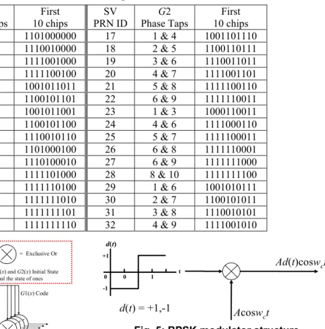
(3) Table 1. C/A code assignments SV PRN ID 1 2 3 4 5 6 7 8 9 10 11 12 13 14 15 16. G2 Phase Taps 2&6 3&7 4&8 5&9 1&9 2 & 10 1&8 2&9 3 & 10 2&3 3&4 5&6 6&7 7&8 8&9 9 & 10. First 10 chips 1101000000 1110010000 1111001000 1111100100 1001011011 1100101101 1001011001 1100101100 1110010110 1101000100 1110100010 1111101000 1111110100 1111111010 1111111101 1111111110. SV PRN ID 17 18 19 20 21 22 23 24 25 26 27 28 29 30 31 32. First 10 chips 1001101110 1100110111 1110011011 1111001101 1111100110 1111110011 1000110011 1111000110 1111100011 1111110001 1111111000 1111111100 1001010111 1100101011 1110010101 1111001010. d(t). G1(x) Shift Register = 1+x3+x10. = Exclusive Or. +1. G1(x) and G2(x) Initial State equal the state of ones. Code Epoch Shift Control. G2 Phase Taps 1&4 2&5 3&6 4&7 5&8 6&9 1&3 4&6 5&7 6&8 6&9 8 & 10 1&6 2&7 3&8 4&9. 0. 1 2 3 4 5 6 7 8 9 10. Ad(t)coswct. t. d(t) = +1,-1. G2(x) Shift Register = 1+x2+x3+x6+x8+x9+x10. Acoswct. Fig. 5: BPSK modulator structure. C/A Code Chips. 1 2 3 4 5 6 7 8 9 10 Phase Taps G2i(x) Code. Fig. 4. Four-channel C/A code generator. CODE. Each satellite transmits a satellite signal that consists of a set of navigation message and a set of independent C/A code which works at 50 bps and 1.023MHz, respectively. Moreover, C/A code is one kind of them of Pseudo Random Noise (PRN) code. Each satellite has a regular PRN code. Therefore, receivers can recognize different satellites utilizing PRN code. The C/A code generator structure is shown in Fig. 4. The C/A code chips pattern is the exclusive-or (XOR) of two 1023-bit patterns, G1(x) code and G2i(x) code. The G1(x) and G2(x) sequences are generated by ten stages shift register which are shown in the following equations (1) and (2) as referred to the shift register input. The G2i(x) patterns are achieved by combining the output of two stages of the G2(x) shift register by exclusive-or. Because each satellite had the same G1(x) and G2(x) sequences, hence only one set of G1(x) and G2(x) sequences are need in the four-channel GPS-DSS baseband system. G1(x) = 1 + x3 + x 10 G2(x) = 1 + x 2 + x 3 + x 6 + x 8 + x 9 + x 10. 1. -1. G1(x) Code. 3.1: COARSE/ACQUISTION GENERATOR. 0. (1) (2). Thirty-two SV PRN ID are generated by Table 1. Table 1 contains tabulation of the G2(x) shift register phase taps, corresponding SV PRN ID and first ten of C/A code. For example, executing the exclusion-or both phase taps 5 and 9 are transmitted data of PRN ID 4 which is presented by full lines in Fig. 4. The G2i(x) code phase selection generate 32 satellites PRN code according to G2(x) phase taps in Table 1. The four exclusive-or are used to choose four satellites PRN code among a set of 32 satellites in G2(x) shift register. The C/A codes are generated by the exclusive-or of G2i(x) code and G1(x) code, where G2i(x) code are selection satellite 4, 9, 14 and 17 PRN ID, respectively. The GPS satellite signal is generated by the exclusive-or C/A code and navigation message, where the navigation message is generated by microprocessor system.. 3.2: BPSK MODULATION The GPS space vehicles (SVs) transmit two carrier frequencies call L1, the primary frequency, and L2, the secondary frequency. The carrier frequencies are modulated by spread spectrum codes with a unique PRN sequence associated with each SV and by the navigation data message. The civil application only uses the signal of L1. However, L1 signal must mix L1 carrier, C/A code and navigation message. The BPSK modulation is shown in Fig. 5. The input of BPSK modulator is from the exclusive-or output of C/A code and navigation message. The output of BPSK modulator can generate a modulation signal for exclusive-or the C/A code and. - 135 -.
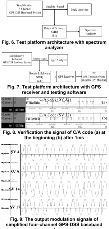
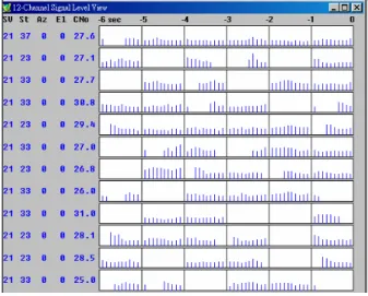
(4) navigation message. When input of BPSK modulator is high (d(t) = +1) then output is normal-phase cosine wave. When input of BPSK modulator is low (d(t) = –1) then output is reversed-phase cosine wave. In Fig. 5, the wc represents signal carrier frequency namely L1 frequency, but the carrier frequency is established 1.023 MHz in this work. We use Xilinx System Generator V7.1 to generate Verilog code for cosine wave function.. 3.3: TEST PLATFORM The test platform architecture with spectrum analyzer for our proposed simplified four-channel GPS-DSS baseband system is shown in Fig. 6. The outputs of simplified four-channel GPS-DSS system are GPS satellite baseband signals which are connected to logic analyzer and Rohde & Schwarz SMIQ. The logic analyzer is to measure the accuracy of satellite signal. However, the GPS satellite baseband signal will be modulated on the frequency of L1 carrier by Rohde & Schwarz SMIQ and then transmits to spectrum analyzer and observe the result. To verify verification the transmission function in our proposed system, we replace spectrum analyzer, and in Fig. 6 by GPS receiver and GPS testing software which architecture is shown in Fig. 7. After the GPS satellite baseband signals are modulated on the frequency of L1 carrier by Rohde & Schwarz SMIQ, the GPS satellite baseband signals will be transmitted to GPS receiver. Finally, the check of the receiver’s accuracy is received the GPS satellite signal by GPS testing software.. Simplificative 4-Channel GPS-DSS Baseband System. Satellite Signal. Logic Analyzer. Rohde & Schwarz SMIQ (L1). Spectrum Analyzer. Fig. 6. Test platform architecture with spectrum analyzer Simplificative Satellite Signal 4-Channel Logic Analyzer GPS-DSS Baseband System. Rohde & Schwarz SMIQ (L1). GPS Receiver. PC GPS Testing Software (Leadtek GPS Monitor). Fig. 7. Test platform architecture with GPS receiver and testing software C/A Code (SV 32) 1111001010. C/A Code (SV 32). 1111001010. (a). (b). Fig. 8. Verification the signal of C/A code (a) at the beginning (b) after 1ms SV 4. SV 9. 4: EXPERIMENTAL RESULTS The simulation of simplified four-channel GPS-DSS baseband system will be simulated by ModelSim SE 5.7g. The C/A code generator simulation is setting at the satellite 32, as shown in Fig. 8(a) and 8(b). We compare the difference the results of C/A code between beginning as Fig. 8(a) and running after 1ms as Fig. 8(b). The results in Fig. 8(a) and 8(b) are the same as in the first 10 chips in Table 1. The C/A code each period is 1ms. Finally, SV 4, SV 9, SV 14 and SV 17 are generated in the four-channel GPS-DSS baseband system and the output signals are shown in Fig. 9. We use Xilinx Xc2s50e FPGA to implement our proposed simplified four-channel GPS-DSS baseband system. The system testing architectures are shown as Fig. 6 and Fig. 7, and they both choose the SV 21 to test and verify the system function. We use spectrum analyzer to measure the output modulation signal in our proposed simplified four-channel GPS-DSS baseband system and the test platform shown in Fig. 6. To easily to check the result, we show the one channel modulation signal measured result in Fig. 10. To verify our proposed system working properly, we use GPS receiver and GPS testing software to receive the output RF signals from our proposed four-channel GPS-DSS baseband system and RF transmitter, Rohde & Schwarz SMIQ which testing platform shown in Fig. 7. The testing results are shown in Fig. 11 and the SV 21. SV 14. SV 17. Fig. 9. The output modulation signals of simplified four-channel GPS-DSS baseband system. Fig. 10. The one channel modulation signal for simplified four-channel GPS-DSS baseband system on L1 carrier with spectrum analyzer. - 136 -.
(5) REFERENCES. Fig. 11. The satellite receives state on the SV 21 by GPS testing software Table 2. Resource used in Xilinx Xc2s50e for GPS-DSS baseband system Proposed Items Slices Flip Flops 4-input LUTs Bonded IOBs GCLKs. [1]. Global Positioning System Overview, http://www.colorado.edu/geography/gcraft/notes/gps/gp s_f.htm. [2]. J. Ashjaee, “On precision of GPS C/A code,” IEEE Aerospace and Electronic System Society, Vol. 3, No. 6, pp. 7-10, June 1988.. [3]. G. Dedes and A. G. Dempster, “Indoor GPS positioning - Challenges & opportunities,” Proceeding of IEEE International Conference on Vehicular Technology, Dallas, Texas, pp. 412-415, September 25-28, 2005.. [4]. C. Rizos, Pseudolite Augmentation of GPS, http://www.gmat.unsw.edu.au/snap/new/news2005.htm #arc.. [5]. Wen-Zheng Lai, Design, Implementation and Testing of a Dual-Frequency GPS Pseudolite Transmitter, Master Thesis, National Cheng Kung University, Tainan Taiwan, 2003.. [6]. Trong-Yen Lee, Yung-Lin Hsu, Che-Cheng Hu, ChiaChun Tsai and Rong-Shue Hsiao, “Design and Implementation of Multi-Channel GPS Simulator,” The Fourth Conference on Communication Applications, pp. 61-66, March 2006.. [6]. Total Usage Used Rate Total Usage Used Rate 768 83 10% 768 165 21% 1536. 83. 5%. 1536. 111. 7%. 1536. 152. 9%. 1536. 299. 19%. 146. 83. 56%. 146. 137. 93%. 4. 2. 50%. 4. 2. 50%. signals are correctly received in this experiment. For comparison the implementation results for GPS-DSS baseband system, we implement our proposed and [6] architectures. The experimental results are shown in Table 2. From Table 2, the used FPGA slices, Flip-Flops and LUTs in our proposed architecture are reduced than the related architecture [6]. Specially, our proposed architecture only uses 10 percent of slices in the Xilinx Xc2s50e.. 5: CONCLUSIONS The GPS Digital Satellite Signal (GPS-DSS) simulator is used to generate satellite signals to verify the function of GPS receiver. The satellite signals are processed and generated by GPS-DSS baseband system. A low-cost simplified four-channel GPS-DSS baseband system is proposed and which includes design of the C/A code generation, navigation messages processing and BPSK modulation used by FPGA system. Furthermore, the simplified GPS-DSS baseband system allows user to rapidly estimate position correctness of the GPS receiver. In this work, we have reduced FPGA slices usage by using IP reuse concept. Experimental results show that our proposed system only uses 10 percent of slices in a low-cost Xilinx Xc2s50e FPGA resource.. - 137 -.
(6)
數據
相關文件
• cost-sensitive classifier: low cost but high error rate. • traditional classifier: low error rate but
An OFDM signal offers an advantage in a channel that has a frequency selective fading response.. As we can see, when we lay an OFDM signal spectrum against the
mNewLine ; invoke the macro This is how you define and invoke a simple macro. The assembler will substitute "call
• When the coherence bandwidth is low, but we need to use high data rate (high signal bandwidth). • Channel is unknown
• When the coherence bandwidth is low, but we need to use high data rate (high signal bandwidth). • Channel is unknown
In order to improve the aforementioned problems, this research proposes a conceptual cost estimation method that integrates a neuro-fuzzy system with the Principal Items
In order to partition the GPS market into different segments, this paper used purchase motives, product attributes and consumer lifestyle as the variables for market
In this study the GPS and WiFi are used to construct Space Guidance System for visitors to easily navigate to target.. This study will use 3D technology to
