A New Control Method for Single-phase Active Power Line Conditioners
Yu-Kang Lo
and Lian-Chen
Kuo
Department of Electronic Engineering National Taiwan Univ. of Science and Technology
Taipei, Taiwan, ROC
Abstract-A new control method for single-phase shunt active power line conditioners (APLC’s) operated under zero average power consumption is proposed in this paper. The amplitude of the sinusoidal source current which is in-phase with the source voltage can be determined from the average value of the instantaneous load power. Then the command current for the shunt APLC is obtained by subtracting the source current from the load current. Neither bulky filter nor time-consuming computation is required. The shunt power compensator supplies all the harmonics of the load current and the source only supplies the fundamental component. Experimental results on a prototype verify the feasibility of the presented scheme.
I. INTRODUCTION
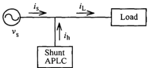
To reshape the distorted input currents caused by the increasing nonlinear and switching-mode loads, many researches have been focused on the power factor correctors recently[ 13. The power capacities handled by these circuits are limited since they are connected in series between the sources and the loads. On the other hand, active power line conditioners (APLC’s) inject harmonic currents into the system as shunt reactive power sources[2-41. The block diagram of a power system with a shunt APLC is shown in
Fig. 1. The voltage sousce PWM inverters are usually
adopted as the power circuits of the shunt APLC’s. Ideally, the shunt APLC neither contributes nor consumes any real power. Thus all the load power is supplied by the source. To achieve a unity input power factor, i,(t) is controlled to be purely sinusoidal and in-phase with the source voltage. That is to say, ih(t) should contains at least all the harmonics of the load current iL(t).
There a r e two time-domain compensation methods described in the literature for the shunt APLC to supply only the reactive part of the load power. The first method utilizes
a 60 Hz filter to extract the fundamental component of the
distorted input current[2]. The cost of the filter elements is
Fig. 1 Block diagram of a power system with a shunt APLC
0-7803-5160-6/99/$10.00 0 1999 IEEE. 1150
considerable if higher order and lower cutoff frequency of the
filter are required. The second approach calculates the
instantaneous reactive power, where the computation circuitry is somewhat complicate[3]. In this paper, a novel control strategy for the shunt APLC with zero average power
consumption is proposed. The amplitude of the source
current is determined from the average value of the instantaneous output power. The command current for the shunt APLC is then obtained by subtracting the source current from the load current. In the following paragraphs, the operation principles of the proposed control method will be discussed. Some experimental results of a prototype system are shown to verify the presented scheme.
11. ZERO POWER CONSUMPTION OF THE SHUNT APLC
Fig. 2 illustrates the detailed diagram of a single-phase power system with a shunt APLC. The load is powered through a full-bridge diode rectifier. It is known that iL(t)
contains fundamental component iLl(t) and harmonics of
other orders. Without compensation, the power factor of the source will be poor even adding an input inductor. To achieve a unity power factor at the source side, i,(t) must be purely sinusoidal and in-phase with v,(t). And to operate the
shunt APLC with zero average power consumption, the
average power supplied by the source, P i , must be equal to
the average power consumed by the load, Po. Considering
that the system is in its steady state, the conservation of power leads to
(1)
P . = - V I = - v s I L 1 ~ c o s + = P o ,
where V, , I, and ILI are the peak amplitudes of v,(t), i,(t) and
iLl(t), respectively, and
+
is the phase difference between v,(t) and iLl(t). From (l), it can be seen that I, is proportional to the load power Po.(2) ih(t) contains all the harmonics of iL(t) and a fundamental component, ihl(t), which is the difference between iLl(t) and i,(t). Since the AC side of the APLC is the source voltage with fundamental frequency, ihl(t) must be out-of-phase with v,(t) in order that the shunt APLC does not manipulate the real power. The statement above can be proved from (1)
and (21,
1 1
‘ 2 s s 2
According to the KCL, ih(t) = iL(t) - i,(t),
ih I (t) = iL I (t)
-
is(t)= IL, sin (wt
+
4)
- 1, sinwt= ILI sin (at
+
+) - lLI sinot cos4-
'L 3 / Shunt APLCJ . J .
I
L
Fig. 2 The discussed single-phase power system.
where o is the fundamental frequency in radians per second. io(t) are of 2nd-order.
then be expressed as:
Normally, the dominant harmonics appeared in v,(t) and The instantaneous output power can p o w = vo(t).io(t)
Z V, (1 + r, 4n2wt) I, (1
+
ri 4n2wt)E V, I, (1
+
r, 4 n 2 o t + ri 4n2wt)= Po ( 1
+
rp .sin2ot), (4)where V, , I, are the DC values of v,(t) and i,(t), and rv , ri and rp are the ratios of the dominant 2nd-order harmonics to V, ,
I, and P o , respectively. It is concluded that the amplitude of
is(t) is proportional to Po., which is the average value or DC
component of po(t). Instead of filtering out the DC
component, the peak and the valley of po(t) are detected by the peak detectors and averaged to obtain the value of Po. The amplitude command of i,(t) is then the product of Po and a proper gain. The block diagram of the proposed control
scheme is shown in Fig. 3. The shunt PWM converter
supplies all the harmonics of the load current and a fundamental component which is out-of-phase. That is, the shunt APLC neither contributes nor consumes any average power. . . . . _ . _ _ _ _ _ _ _ _ _ _ _ _ - . - - - . - - - . - - .
io
~ vs < . . . - .-
k l vs UFig. 3 The block diagram of the proposed peak output power detection control scheme.
111. EXPERIMENTAL RESULTS
Some experimental results on a prototype system have been
V, = 50& V, CO = 470pF,
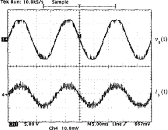
Fig. 4 shows the waveforms of v,(t) and i,(t). recorded. The system parameters are listed as follows.
= 55R, V, = 50 V
It can be seen that the power factor is almost unity. The rms value of i,(t) is 1A and the average input power P, is 50W. The output power Po is calculated to be about 45W. The power loss due to the nonideal circuit elements must be taken into account when designing the feedback gain. Here we assume that the overall efficiency of the system is 90%. Illustrated in Fig. 5 are the waveforms of i,(t), ih(t) and iL(t), where the
conformity to the KCL can be observed. Under the
proposed scheme, the source only supplies the in-phase fundamental current, while ih(t) contains all the harmonics and the out-of-phase fundamental component. It can then be concluded that the shunt APLC consumes zero average power.
TeK RUn: lO.OkS/s Sample
[
__
-. --T. - - - _ - ]I '
" " " " "" " " " ' !
" ' * ' ' ' " " "" '1
! , 5.00 v h a OOmS Line/ 667m Ch4 10 OmVFig. 4 The waveforms of v,(t) and is(t). Time: 5 ms/div; voltage: 50 V/div; current: 2 Ndiv.
i
I
I
Fig. 5 The waveforms of is(t), ih(t) and iL(t). Time: 5 ms/div; current: 2 Ndiv.
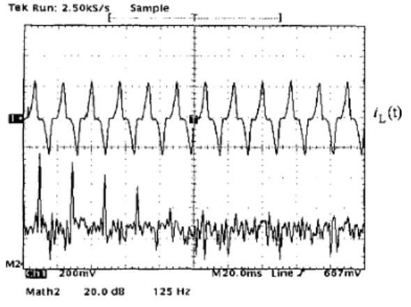
Fig. 6(a) shows the waveform of iL(t) and its spectrum, where odd-order harmonics appear besides a fundamental. Fig. 6(b) shows the waveform of i,(t) and its spectrum. It can be seen that the fundamental component dominates and
the source supplies all the average real power. The
waveform of ih(t) and its spectrum are depicted in Fig. 6(c).
Tek Run 2 soks/s Sample
[ T 1
I " ' " " " ' ' * ' " ' " '
omv
MZ
Math2 2 0 Ode 1 2 5 H Z
Fig 6(a) The waveform of iL(t) and its spectrum Time 20 msldiv, frequency 125 Hddiv , current 2 N d i v
Tek Run 2 S O k s I s Sample
1 I ' " "" ''8''" " " I " " " " " ' ' " " " " ' I M . mr L i n e 1 , ,
i ,
, * , , , , , , , . bD,,mJ Math2 2 0 . 0 d p 'pi,"",':Fig. 6(b) The waveform of i,(t) and its spectrum. Time: 20 ms/div; frequency: 125 Hddiv.; current: 2 Ndiv.
Tek Run: 2 Soks/s Sample
1 I
1
c h -m r Llnef 6 20 OdB 125 H ZFig 6(c) The waveform of ih(t) and its spectrum Time 20 msldiv, frequency 125 Hddiv , current 2 N d i v
The shunt APLC injects all the harmonics of iL(t) into the system. The fundamental component of ih(t), however, does not contribute any real power as discussed in Section 11.
The response of the presented system subject to load variation is recorded in Fig. 7. The load resistor
R,,
is changed from 55R to 22R. It can be clearly seen that the load power Po is changed from 45W to 105W, and the rms value of l,(t) is changed from 1A to 2.4A. The overall efficiency of the system remains around 90%. The response time is less than one period as observed.Tak 2 50kS/r 4 5 ACqS
T 1
I " " " " " ' ' ' ' ' '
I " " " " '
Fig. 7 The responses of output power Po and the source current i,(t) under load change. Time: 20 ms/div.; power: 45 W/div; current: 2 Ndiv
IV. CONCLUSIONS
In this paper, a novel control scheme for a shunt APLC operated under zero average power is presented. By sensing the DC value of the output power through the peak detection, the amplitude of the source current required by the source to supply all the average power can then be determined. The shunt APLC injects all the reactive power. Thus a nuity
input power factor can be achieved. Experiments on a
prototype system show satisfactory results. The proposed scheme can be applied to three-phase system as well.
REFERENCES
[ 13 J. C. Salmon, "Circuit topologies for single-phase
voltage-doubler boost rectifier," IEEE Trans. Power Elec. vol. 8, no. 4, 1993, pp. 521-529.
[2] H. Kawahira, T. Nakamura, and S. Nakazawa, "Active power filters," in Proc. JIEE IPEC-Tokyo, 1983, pp. 981.
[3] H. Akagi and Y. Kanazawa, and A. Nabae,
"Instantaneous reactive power compensators comprising switching devices without energy storage components,"
IEEE Trans. Ind. Appl. vol. 20, p. 625, 1984.
[4] H. Akagi, "Trends in active power line conditioners,"
IEEE Trans. Power Elec. vol. 9, no. 3, p. 263, 1994.