Analysis of the carrier-suppressed
single-sideband modulators used to mitigate Rayleigh
backscattering in carrier-distributed PON
C. W. Chow,1,* C. H. Wang,1 C. H. Yeh,2 and S. Chi1,3,41Department of Photonics and Institute of Electro-Optical Engineering, National Chiao Tung University, Hsinchu
300-10, Taiwan
2Information and Communications Research Laboratories, Industrial Technology Research Institute, Hsinchu 310-40,
Taiwan
3Department of Electrical Engineering, Yuan Ze University, Chung-Li 320-03, Taiwan 4[email protected]
Abstract: By using the carrier-suppressed single-sideband (CS-SSB)
modulation, the Rayleigh backscattering (RB) experienced by the uplink signal can be effectively mitigated due to the reduction of the spectral overlap between the uplink signal and the distributed optical carrier. In this work, we first introduce the theoretical analysis of the CS-SSB generation using the dual-drive MZM (DD-MZM)-based and a dual-parallel MZM (DP-MZM)-based optical networking units (ONUs). Due to the different modulation mechanisms of the two CS-SSB modulations, the frequency components of the generated CS-SSB signals are also different. The transmission performance and the dispersion tolerance of the uplink signals generated by the two CS-SSB modulators are also analyzed and discussed. ©2011 Optical Society of America
OCIS codes: (060.0060) Fiber optics and optical communications; (060.2360) Fiber optics links
and subsystems; (350, 4010) Microwaves.
References and links
1. L. Y. Chan, C. K. Chan, D. T. K. Tong, F. Tong, and L. K. Chen, “Upstream traffic transmitter using injection-locked Fabry-Perot laser diode as modulator for WDM access networks,” Electron. Lett. 38(1), 43–45 (2002). 2. W. Hung, C. K. Chan, L. K. Chen, and F. Tong, “An optical network unit for WDM access networks with
downstream DPSK and upstream remodulated OOK data using injection-locked FP laser,” IEEE Photon. Technol. Lett. 15(10), 1476–1478 (2003).
3. C. W. Chow, “Wavelength remodulation using DPSK down-and-upstream with high extinction ratio for 10-Gb/s DWDM-passive optical networks,” IEEE Photon. Technol. Lett. 20(1), 12–14 (2008).
4. G. Talli, C. W. Chow, E. K. MacHale, and P. D. Townsend, “Rayleigh noise mitigation in long-reach hybrid DWDM-TDM PONs,” J. Opt. Netw. 6, 765–776 (2007).
5. S.-K. Liaw, S.-L. Tzeng, and Y.-J. Hung, “Power penalty induced by Rayleigh backscattering in a bidirectional wavelength-reuse lightwave system,” Proc. CLEO (2001) CThL54.
6. G. Talli, D. Cotter, and P. D. Townsend, “Rayleigh backscattering impairments in access networks with centralised light source,” Electron. Lett. 42(15), 877–878 (2006).
7. C. W. Chow, G. Talli, and P. D. Townsend, “Rayleigh noise reduction in 10-Gb/s DWDM-PONs by wavelength detuning and phase-modulation-induced spectral broadening,” IEEE Photon. Technol. Lett. 19(6), 423–425 (2007).
8. C. W. Chow, G. Talli, A. D. Ellis, and P. D. Townsend, “Rayleigh noise mitigation in DWDM LR-PONs using carrier suppressed subcarrier-amplitude modulated phase shift keying,” Opt. Express 16(3), 1860–1866 (2008). 9. J. Prat, M. Omella, and V. Polo, “Wavelength shifting for colorless ONUs in single-fiber WDM-PONs,” Proc.
OFC (2007), Anaheim, CA, OFE1.
10. C. H. Wang, C. W. Chow, C. H. Yeh, C. L. Wu, S. Chi, and C. Lin, “Rayleigh noise mitigation using single sideband modulation generated by a dual-parallel MZM for carrier distributed PON,” IEEE Photon. Technol. Lett. 22(11), 820–822 (2010).
11. C. W. Chow, and C. H. Yeh, “Mitigation of Rayleigh backscattering in 10-Gb/s downstream and 2.5-Gb/s upstream DWDM 100-km long-reach PONs,” Opt. Express 19(6), 4970–4976 (2011).
12. C. W. Chow, C. H. Yeh, L. Xu, and H. K. Tsang, “Rayleigh backscattering mitigation using wavelength splitting for heterogeneous optical wired and wireless access,” IEEE Photon. Technol. Lett. 22(17), 1294–1296 (2010).
1. Introduction
Owing to the cost-effectiveness, passive optical network (PON) is emerging as a promising access network architecture to cope with the fast-growing bandwidth demand by end-users. In order to further reduce the cost for providing broadband services, long-reach (LR) PONs using wavelength division multiplexed (WDM) centralized light sources (CLS) and reflective, wavelength-insensitive modulators at the optical networking units (RONUs) [1–4] have been widely considered for the future access networks. By implementing the WDM-LR-PON in a loop-back configuration, the CLS is modulated with the uplink data at the RONU and sent back to the head-end office (HO). However, when using a single feeder fiber to connect the HO and the RONU, the uplink signal will experience Rayleigh backscattering (RB) interferometer beat noise generated by the distributed continuous wave (CW) carrier [5,6]. Mitigation of the RB noises is one of the key issues in implementing the carrier distributed PON [7,8].
Recently, using a dual-drive Mach-Zehnder modulator (DD-MZM)-based optical network unit (ONU) [9] or using a dual-parallel MZM (DP-MZM)-based ONU [10] to generate carrier suppressed-single sideband (CS-SSB) uplink signals are attractive since the wavelength of the uplink signal can shift away from the distributed CW carrier. Hence the RB interferometric beat noise can be effectively reduced owing to the reduction of the spectral overlap between the distributed CW carrier and the uplink signal. Although both kinds of modulators can produce the CS-SSB uplink signals, we found that the frequency components of the generated CS-SSB signals are different due to the different modulation mechanisms. Hence, their dispersion tolerances and transmission performances are different.
In this work, we first introduce the theoretical analysis of CS-SSB carrier generations using the DD-MZM-based and the DP-MZM-based ONUs. Then the transmission performances and the dispersion tolerances of the uplink signals generated by the two CS-SSB modulators are also analyzed and discussed. Results show that the CS-SSB signal generated by the DP-MZM has better transmission performance. Based on these results, an experiment WDM-LR-PON using carrier distribution with DP-MZM-based ONU is implemented and evaluated. Experimental results show that the proposed WDM-LR-PON can support 75 km extended reach transmission with a passive split-ratio of 64.
2. Theoretical analysis and experiments of CS-SSB modulations
sin(ω0t) cos(ω0t) sin(ω0t) cos(ω0t) ω0 ω0-2ωRF ω0-ωRF ω0+2ωRF ω0+3ωRF (i) ω0-ωRF ω0+3ωRF (ii) (a) (b) CW PC bias tee +90° bias tee RF signal Phase shifter 2 V CW PC bias tee +90° bias tee RF signal Phase shifter 2 V 2 V data V V CW PC RF signal bias tee +90° bias tee MZM1 MZM2 MZM3 Phase shifter 2 V data V V CW PC RF signal bias tee +90° bias tee MZM1 MZM2 MZM3 Phase shifter ω0 -3ωRF
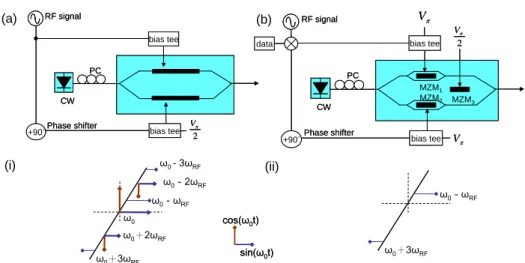
Fig. 1. The architectures of the CS-SSB generations using (a) DD-MZM: dual-drive MZM (b) DP-MZM: dual-paralleled MZM. Insets: vector diagrams of (i) DD-MZM; (ii) DP-MZM.
Figure 1 shows the architectures of the CS-SSB signals generated by the (a) DD-MZM-based and the (b) DP-MZM-DD-MZM-based ONUs. For the architecture of the DD-MZM as shown in Fig. 1(a), the electric field at the upper arm is given by (1):
0 ( ( )) _ 0 0 0 0 0 0 1 1 ( ) Re cos( ( )) 2 2 1cos cos ( ) sin sin ( ) ,
2 j t t DD MZM upper E t E e E t t E t t t t (1)
where E0 and ω0 denote the amplitude and angular frequency of the input optical carrier
respectively.
( )t = mcos(ωRFt), where m and ωRF denote the modulation depth and theangular frequency of the electrical driving signal. Then we replace
( )t by mcos(ωRFt) andsolve the Eq. (1) by using the Bessel functions. The higher orders (≧ 4th) Bessel terms can be neglected because the coefficients are small. The electric field at the output of upper arm can be simply as (2):
_ 0 0 0 2 0 0
1 0 0
3 0 0
1
( ) { ( ) cos ( )[cos( 2 ) cos( 2 )]
2 ( )[sin( ) sin( )] ( )[sin( 3 ) sin( 3 )]}. DD MZM upper RF RF RF RF RF RF E t E J m t J m t t t t J m t t t t J m t t t t (2)
For the lower arm of DD-MZM, the phase shift is negative because of the electric field is opposite to that of the upper arm, as well as the phase is shifted by a 90° due to the phase
shifter. So
( )t should be expressed as mcos(ωRFt + π/2) = -msin(ωRFt). Because of the sameconcept mentioned in upper arm, the electric field at the lower arm can be written as (3):
_ 0 0 0 2 0 0
1 0 0
3 0 0
1
( ) { ( ) cos ( )[cos( 2 ) cos( 2 )]
2 ( )[cos( ) cos( )] ( )[cos( 3 ) cos( 3 )]}. DD MZM lower RF RF RF RF RF RF E t E J m t J m t t t t J m t t t t J m t t t t (3)
The phase of the lower arm should be shifted by another 90° because of the Vπ/2 DC Bias.
Hence, we can see that the + ωRF electric field components can be cancelled at the output port
of the DD-MZM as shown in the inset (i) of Fig. 1. Then, we chose a modulation depth (m) to
suppress the central electrical component, i.e. the zero-order of the Bessel function J0(m) = 0.
Hence, the CS-SSB signal can be successfully generated when m 2.4.
For the DP-MZM (Fig. 1(b)), it consists of three single-arm MZMs, and we named them
as MZM1, MZM2 and MZM3. We applied driving voltage of Vπ to MZM1 and MZM2 and
based on the same concept as used in the DD-MZM analysis. The electric field at MZM1
output is given by (4): 1 0 1 0 0 3 0 0 1 ( ) {2 ( )[sin( ) sin( )] 2 2 ( )[sin( 3 ) sin( 3 )]}. MZM RF RF RF RF E t E J m t t t t J m t t t t (4)
For MZM2, the phase is shifted by a 90° phase shifter and then the electric field at MZM2
output is given by (5): 2 0 1 0 0 3 0 0 1 ( ) { 2 ( )[cos( ) cos( )] 2 2 ( )[cos( 3 ) cos( 3 )]}. MZM RF RF RF RF E t E J m t t t t J m t t t t (5)
Similarly, the phase at the MZM2 output should be shifted by another 90° because of the
Vπ/2 DC Bias. The electric field components at the output port of the DP-MZM are shown
inset (ii) of Fig. 1. We can observe that the + ωRF frequency component generated by the
DP-MZM is the dominant, and it is independent of the driving modulation index. This also implies that we do not need to over-drive the modulator in order to achieve carrier wavelength suppression as in the case of the DD-MZM.
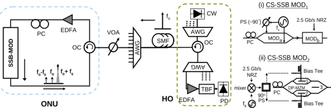
Then we carried out the network experiments using the two kinds of CS-SSB ONUs. Figure 2 shows the proposed network architecture of the bi-directional carrier distributed PON. The CW carrier transmitted through a single mode fiber (SMF) towards the CS-SSB modulator inside the ONU, via a pair of AWGs (Gaussian shaped, 3-dB width of 50 GHz). There is no active component between the HO and the ONU, and the PON is fully passive. A variable optical attenuator (VOA) was used to emulate the PON split-ratio. In the colorless ONU, a loop-back configuration was achieved by an optical circulator (OC). As shown in the
insets of Fig. 2, two different CS-SSB modulators (MODs) were used. For CS-SSB MOD1 as
shown in inset (i) of Fig. 2, the DD-MZM was driven in-phase and quadrature-phase by an
electrical sinusoidal signal at frequency fs (10 GHz) generated by a radio frequency (RF)
signal synthesizer. Hence the output of the DD-MZM (MODa in inset (i)) produced a
wavelength shift of 10 GHz to the CW carrier. Then MODb encoded a 2.5 Gb/s
non-return-to-zero (NRZ) data at pseudorandom binary sequence (PRBS) 231-1. For the CS-SSB MOD2 as
shown in inset (ii) of Fig. 2, the baseband 2.5 Gb/s NRZ data at PRBS 231-1 was first
up-converted via a RF mixer with an electrical sinusoidal signal at frequency fs (10 GHz)
generated by a RF signal synthesizer. The up-converted signal was then applied to the DP-MZM to produce the CS-SSB signal, as described in the beginning of this section. Our previous study [11] showed that a 10 GHz wavelength-shift can provide a significantly upstream signal improvement against RB noise in a 2.5 Gb/s NRZ signal.
All the modulators used in the studies are commercially available. The modulation
bandwidths and insertion losses of MODa and MODb are 9 GHz and 12 GHz; and 5 dB and
3.5 dB, respectively. The Vpi of MODa and MODb are 2.6 V at complementary driving and 5
V respectively. The DP-MZM is also called differential quadrature phase shift keying (DQPSK) modulator. The modulation bandwidth and the insertion loss of the DP-MZM are
12 GHz and 7 dB respectively. The Vpi of the DP-MZM is 5.5 V. For the case of CS-SSB
MOD1, a shared DD-MZM (MODa) could be located at the remote node [12] to simplify each
ONU; however active components, such as electrical power supply and high speed (~10 GHz) diving circuit are required at the remote node.
VOA fo fo+ fs fo-fs fo fo+ fs fo-fs OC PC fo SMF SMF OC EDFA TBF AWG AWG AW G PD CW SSB -M OD EDFA ONU HO MODb fs PS (~90°) MODa 2.5 Gb/s NRZ (i) CS-SSB MOD1 PC 2.5 Gb/s NRZ 90o PS fs Bias Tee mixer Bias Tee (ii) CS-SSB MOD2 1 2 1 2 3 DP-MZM PC
Fig. 2. Proposed carrier distributed LR-PON using carrier suppressed-single sideband (CS-SSB) modulation. TBF: tuneable bandpass filter, OC: optical circulator, PC: phase shifter. Insets: (i) CS-SSB MOD1; MODa: dual-drive MZM, MODb: single-arm MZM, PS: phase
shifter; (ii) CS-SSB MOD2; DP-MZM: dual-paralleled MZM. 3. Results and discussion
Figure 3 shows the experimental optical spectra of the CW carrier (carrier-RB) and uplink data. We are interested to observe that at the center wavelength, where the spectral overlap between CW carrier and the uplink signal is obviously reduced due to the CS-SSB modulation. The interferometric noise was significantly improved due to the reduced spectrum overlap. Due to the different modulation mechanism of the two CS-SSB MODs, the frequency components of generated CS-SSB are different. By comparing the vector diagrams in Fig. 1 to the optical spectra of the CS-SSB signals generated by these two MODs, we can
over-drive the DD-MZM to suppress the center wavelength, i.e. the zero-order of the Bessel
function J0(m) = 0, the power levels of other frequency components will increase. For the
CS-SSB MOD2, good frequency component cancellation of the center wavelength and the 1st
ordered lower-sideband can be observed. Hence, from the experiment and the vector diagram
model, CS-SSB MOD2 can produce a pure CS-SSB signal with other frequency components
suppressed. Received power (dBm) -50 -48 -46 -44 -42 -40 -38 -36 -Log(B ER) 2 4 6 8 10 12 b2b 50km 100km b2b 50km 100km CS-SSB-MOD1 CS-SSB-MOD2 -40 -30 -20 -10 0 -50 -40 -30 -20 -10 0 1548.3 1548.4 1548.5 1548.6 1548.7 1548.8 -50 -40 -30 -20 -10 0 (b) (a) Upstream signal Carrier-RB 1548.3 1548.4 1548.5 1548.6 1548.7 1548.8 -40 -30 -20 -10 0 Upstream signal Carrier-RB Po w e r (dB m)
Fig. 3. Experimental optical spectra of CW carrier (carrier-RB) and upstream signal and signal-RB of (a) CS-SSB MOD1,
(b) CS-SSB MOD2
Fig. 4. BERs versus received optical power for uplink traffic using the two CS-SSB MODs applied in the proposed architecture with different SMF transmission distances.
Numerical analysis of transmission performances for the two CS-SSB signals was performed using VPI TransmissionMaker V7.5. Figure 4 shows the simulation results of the bit error rate (BER) versus received power of both CS-SSB signals. The BER was measured
using the built-in function in VPI. For the signal generated by the CS-SSB MOD1, ~1 dB
penalty is observed after 50 km SMF transmission when compared to the back-to-back (b2b), and an error floor appears after transmission of 100 km SMF (dispersion parameter: 17
ps/nm/km). The optical filters used for both CS-SSB-MOD1 and CS-SSB-MOD2 in the BER
measurements in Fig. 4 are the same, and the filter bandwidth is 50 GHz. For the signal
generated by CS-SSB MOD2, the transmission distance can reach to 100 km SMF with
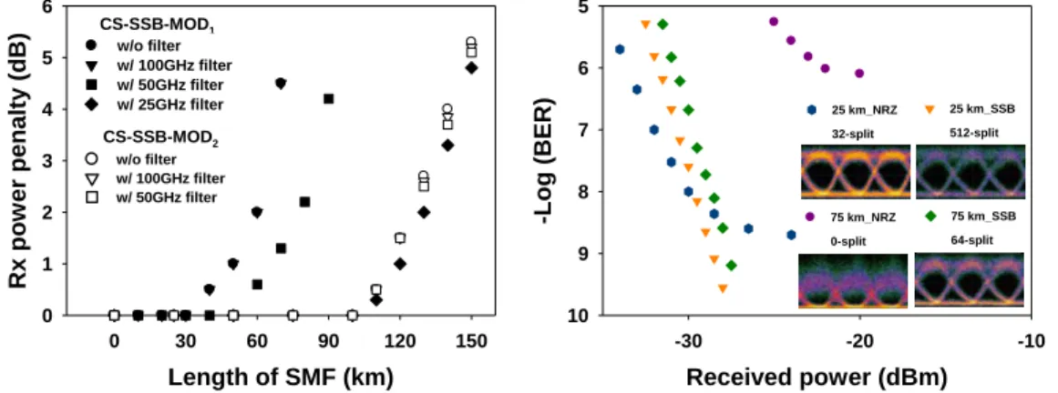
negligible power penalty. From these results, we can see that the transmission performances are very different even both of them are performing CS-SSB modulation. In order to figure out what is the main reason to cause the difference, we further investigate the dispersion tolerant of the two CS-SSB MODs. Figure 5 shows the receiver (Rx) power penalties versus dispersion (set by using different lengths of SMFs) of both CS-SSB signals after passing through different Gaussian-shaped optical filters with different bandwidths. The chromatic dispersion is related to the spectral width of the signal. For the signal generated by the
CS-SSB MOD1, the dispersion tolerant can be improved by limiting the spectral width of the
signal. However, by using a 25 GHz optical filter, an insertion loss of ~3 dB will be
introduced. For the signal generated by the CS-SSB MOD2, the dispersion tolerant is
independent of the filter bandwidths, showing that the signal does not require an optical filter to limit its bandwidth in the transmission.
From above numerical analysis, we can see that the uplink signal generated by the DP-MZM has better transmission performance. Based on the result, an experiment LR-PON using carrier distribution with DP-MZM-based ONU was implemented and evaluated. As we know that the optical power splitting capability is another important concern in a WDM-TDM PON since it is related to the per-subscriber cost issue. Here, we experimental study the split-ratio of the proposed LR-PON. Figure 6 shows the BER performances of uplink CS-SSB signal
using fs = 10 GHz and the conventional NRZ signals at different split-ratios in the
transmission link as shown in Fig. 2. The corresponding eye diagrams are shown in the insets. For the CS-SSB NRZ signal, high split-ratio of 512 can be achieved after transmission of 25
km SMF; while for conventional NRZ signal, only 32 splits can be achieved. When extending the transmission length to 75 km SMF, 64 splits can be achieved in the CS-SSB signal.
However, for conventional NRZ signal, an error floor appeared at BER of 106.
Received power (dBm) -30 -20 -10 -Log (B ER) 5 6 7 8 9 10 25 km_NRZ 32-split 25 km_SSB 512-split 75 km_SSB 64-split 75 km_NRZ 0-split Length of SMF (km) 0 30 60 90 120 150 R x pow er penalty (dB ) 0 1 2 3 4 5 6 w/o filter w/ 100GHz filter w/ 50GHz filter CS-SSB-MOD1 CS-SSB-MOD2 w/o filter w/ 100GHz filter w/ 50GHz filter w/ 25GHz filter Length of SMF (km) 0 30 60 90 120 150 R x pow er penalty (dB ) 0 1 2 3 4 5 6 w/o filter w/ 100GHz filter w/ 50GHz filter CS-SSB-MOD1 CS-SSB-MOD2 w/o filter w/ 100GHz filter w/ 50GHz filter w/ 25GHz filter
Fig. 5. BERs versus dispersion arising from transmitting in SMF when using the two CS-SSB MODs applied in the proposed architecture with different SMF transmission distances.
Fig. 6. BER performances of uplink CS-SSB NRZ signals and conventional NRZ signals with different split ratio in the transmission link. Insets show the corresponding eye diagrams.
4. Conclusion
Recently, using a DD-MZM-based ONU or using a DP-MZM-based ONU to generate the CS-SSB uplink signals are attractive to effectively mitigate the RB interferometric beat noise. Although both kinds of modulators can produce the CS-SSB uplink signals, we found that the frequency components of the generated CS-SSB signals are different due to the different modulation mechanisms. In this work, we first introduce the theoretical analysis of CS-SSB carrier generations using the DD-MZM-based and the DP-MZM-based ONUs. Then network experiments using two kinds of the MODs are performed. By comparing the vector diagrams in the model to the experimental optical spectra of the CS-SSB signals generated by these two MODs, we can observe there is a good match between them. Numerical analysis of the transmission performances and the dispersion tolerances of the uplink signals generated by the two CS-SSB modulators are also analyzed and discussed. Results show that the CS-SSB signal generated by the DP-MZM has better transmission performance. Based on these results, an experiment WDM-LR-PON using carrier distribution with DP-MZM-based ONU is implemented and evaluated. Experimental results show that the proposed WDM-LR-PON can support 75 km extended reach transmission with a passive split-ratio of 64.
Acknowledgements
This work was supported by the National Science Council, Taiwan under Contracts NSC-98-2221-E-009-017-MY3 and NSC-99-2622-E-009-013-CC2.