Electro-optically and all optically addressed spatial light modulator
devices based on organic-inorganic hybrid structures
Vera Marinova
1,2*, Shiuan Huei Lin
3and Ken Yuh Hsu
1 1Department of Photonics, National Chiao Tung University, Hsinchu 30010, Taiwan
2Institute of Optical Materials and Technologies, Sofia 1113, Bulgaria
3Department of Electrophysics, National Chiao Tung University, Hsinchu 30010, Taiwan
ABSTRACT
The paper reviews two types of organic-inorganic hybrid structures: electro-optically addressed and all optically addressed that can be used as spatial light modulator devices, operating in a transmission mode. Both hybrid devices are assembled by inorganic Bi12SiO20 (BSO) crystals and organic liquid crystals (LC). The electro-optically controlled
device demonstrates very high beam-amplification values at Raman–Nath regime of diffraction whereas all optically controlled device operates at Bragg matched regime of diffraction allowing sub-micron spatial resolution. Phase modulation ability has been demonstrated supporting possibilities for applications in adaptive optics, information processing and display technologies.
Keywords: photoconductive inorganic crystals, liquid crystals, optically addressed spatial light modulator
INTRODUCTION
Optical modulators play important role for light control and manipulation. Depending of the principle of operation they can be categorized into electro-optical, all optical, thermo-optical, magneto-optical, acousto-optical, etc. [1-2]. Among optical modulators, spatial light modulators (SLM) “spatially modulates” a coherent beam and consequently are used to modulate amplitude, phase or polarization of the light in space and time. Currently, SLM are extensively applied in modern photonics as components of 3D holographic display technology, in optical computing, holographic data storage and optical information processing.
Usually, SLM are divided to two basic types: Electrically Addressed SLM (EASLM) that “converts” electrical signals to spatial modulation and Optically Addressed SLM (OASLM) that “converts” incoherent light to spatial modulation. For example, OASLM possess several key advantages over EASLM as fast temporal response, incoherent-into coherent image conversion and high spatial resolution without necessity of pixelated electrodes. Generally, OASLM consists of photoconductor (photosensor) and electro-optic material (usually liquid crystal (LC)), separated by dielectric mirror [3]. Typically photosensor materials are Si:H as well as crystalline silicon, sillenite type crystals, ZnO and As-Se layers [4-6]. Among them, Bi12SiO20 (BSO) crystals are known as one of the perfect components for OASLM due to
their excellent photoconductivity and high dark resistivity [7,8]. Moreover, when doped with appropriate elements their photosensitivity can be shifted to preferred wavelengths that open further opportunities to develop OASLM operating at near infrared spectral range [9-12].
In this work we present two types of OASLM devices based on organic-inorganic hybrid structures: electro-optically addressed and all electro-optically addressed.
- The first type of device is based on BSO inorganic crystal, LC layer and transparent conductive layers. Its operation principle relays on an electro-optical control of LC birefringence that allows spatial modulation of the amplitude or the phase of the incident beam.
- The second type (all optically controlled device) is assembled by BSO inorganic crystal and polymer dispersed liquid crystal (PDLC) layer. Its operation principle relays on surface activated photorefractive effect, photoinduced in the inorganic substrate, which is strong enough to penetrate into the LC layer thus acting as a driving force for LC re-alignment and refractive index modulation. Such configuration is simple and easy to fabricate, without need of conductive layers, alignment layers and polarizers. Moreover, all optically controlled device operates at Bragg matched regime of diffraction, where sub-micron spatial resolution can be achieved.
2. EXPERIMENTAL RESULTS AND DISCUSSION 2. Electro-optically controlled hybrid structure.
2.1 Device fabrication.
Electro-optically controlled structure consists of BSO crystal as photoconductive substrate [13] and a glass substrate, arranged into a cell (thickness of 12 µm). Both substrates were preliminary coated with the transparent indium tin oxide (ITO) conductive layers from one side and the opposite sides (contacting with the LC) with polyvinyl alcohol (PVA) in order to acquire planar alignment of LC molecules. After assembling the cell, the LC (nematic phase, MLC-2070 type) was injected by the capillary method. The measured driving voltage of fabricated organic-inorganic device was 3.2 V (r.m.s) at1 kHz frequencies.
2.2 Holographic recording at Raman-Nath regime of diffraction.
The two-wave mixing experiments were performed using 532 nm Verdi laser with linear polarization, oriented parallel to the LC director and equal intensities of both beams (Fig.1). The beam interference creates an intensity fringe pattern which induces a local re-orientation of the LC molecules and formation of refractive index grating inside the LC layer with a fringe space
Λ=λ/(2 sin(θ/2) ) (1)
where θ is the intersection angle between the two beams and λ is the wavelength.
As it seen from Fig.1 several diffracted beams (0, ±1, ± 2,…) has been detected at the output of our hybrid device. Since the thickness of the LC layer (d) is much less than the fringe space Λ (d << Λ), the grating recorded in the LC layer acts as a thin hologram at Raman-Nath regime of diffraction.
s E p E 3 − E 2 − E 1 − E 0 E 1 + E 2 + E 0 V d - BSO crystal - glass - alignment layer - conductive layer 0 +1 -1 -2 +2 -3 +3 532 nm M M M M LC θ Legend: M-mirror, L-lens, BE-beam expander, λ/2- half-wave plate λ/2
λ/2
BE
L
PBS
Fig.1.Two-wave mixing (Ep and Es are the amplitudes of the pump and signal beams) in BSO/LC structure and diffracted orders at Raman Nath regime of diffraction (right side).
Afterwards, the ratio between the two interacting beams, noticed as pump beam IP (high intensity) and signal
beam IS (weak intensity) was fixed to 1/70. The experiment allows to measure the two-wave mixing gain as G = IsꞋ/Is (0),
where Is (0) is the input signal intensity (without pump light) and Is' is the amplified signal after the device (signal beam
plus pump beam). At grating period of Λ = 93 µm we measured the gain value of G = 5. Subsequently, the gain coefficient Г (cm-1), defined as the saturated value of the signal beam IsꞋ divided by the initial value of the signal beam Is,
is expressed by [14]:
The calculated gain coefficient of Г = 1350 cm-1 is similar to those reported for other organic-inorganic hybrid structures, operating at visible spectral range [15,16]. Despite that very high gain coefficient has been achieved, due to the multiple-order diffracted beams, the angle between the pump and probe is restricted to less than a few degrees, which limits the applications.
2.3. Electro-optically controlled hybrid structure as OASLM device.
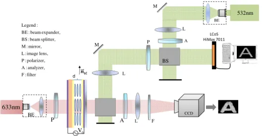
Figure 2 shows an optical set-up where the proposed structure works as OASLM device. An image pattern of character A was displayed using liquid crystal on silicon (LCoS) (HiMax7011 type) SLM-device source and addressed on BSO/LC hybrid device. The image pattern, modulated at real time was captured by a CCD camera (640 x 480 pixels). Such demonstration reveal phase modulation ability of BSO/LC hybrid structure and opens further prospective to extend the operating region to near infrared spectral range by selecting appropriate inorganic substrate.
nm 633 L L BE BE M M A nm 532 filter : F analyzer, : A polarizer, : P lens, image : L mirror, : M splitter, beam : BS expander, beam : BE : Legend LCoS HiMax 7011 P A CCD BS F P L 0 V d LC BS
Fig.2. Optical set-up demonstrating phase modulation ability of BSO/LC hybrid structure.
3. All optically controlled hybrid structure.
Although significant beam amplification values have been achieved in electro-optically controlled BSO/LC structure, the appearance of several diffraction orders limits the practical applications. In this aspect, search for all optically controlled structure operating at Bragg match regime of diffraction is of prime importance.
A novel type of organic-inorganic structure, allowing all optically controlled processes, has been proposed first theoretically by Tabiryan and Umeton [17]. The idea relays on the surface activated photorefractive effect typical for inorganic substrate and in more particular the photoinduced periodic space charge field which can penetrate into the LC layer and reorient the LC molecules, consequently modulating the refractive index. Except simple fabrication processes, the fundamental advantage is the ability of the recorded holographic gratings to act as a thick hologram at Bragg match regime of diffraction that allows sub-micron resolution.
3.1 Device fabrication.
All optically controlled structure was assembled by photoconductive BSO crystal substrate and a glass substrate, arranged into a cell (10 µm thickness), filled with polymer dispersed liquid crystal (PDLC) layer (Fig. 3(a)). The PDLC was fabricated by mixing UV-curable monomer NOA65 (Norland) and nematic LC host at 30:70 wt %. The LC/monomer mixture was injected into an empty cell and exposed with UV light (λ = 365 nm) for 15 min. In addition, a reference glass/PDLC/glass cell, made by PDLC layer between two glass substrates with the same thickness has been prepared for comparison.
PDLC consists of micron-sized droplets of LCs randomly dispersed in a transparent polymer matrix [18]. Naturally, PDLC films are opaque due to the refractive index mismatch between the polymer matrix and the LC and can be switched from the light-scattering to the transparent state by the application of an electric field, which support the refractive indexes match between the aligned LC and polymer matrix. Furthermore, since the polymer binder defines the
droplets orientations, there is no necessity of alignment layer deposition as well as use of polarizers. This fact permits the photo-generated space-charge field inside the BSO inorganic substrate to penetrate directly into the PDLC layer and to modulate the refractive indexes.
3.2. Holographic recording at Bragg match regime of diffraction.
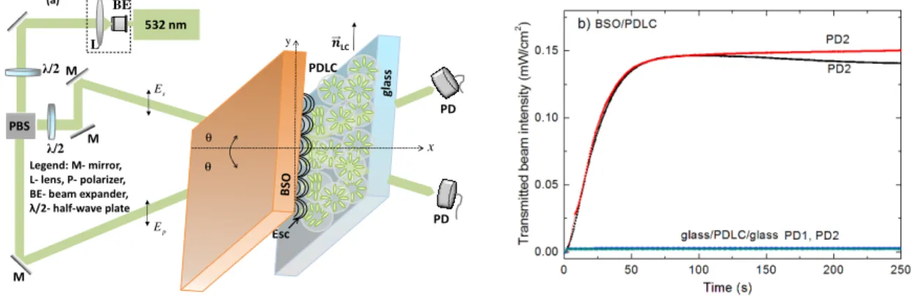
The two-beam coupling experiments have been performed using 532 nm Verdi laser. The temporal behavior of both interacting beams (linearly polarized, 1:1 ratio) inside the structure is shown at Fig.3 (b). As it seen, at the beginning the two beams propagate together since the BSO/PDLC requires time to reverse its scattering state to the transparent state [11]. After several seconds, a constructive and deconstructive interference occur, which is indication of π/2 phase shift between the light pattern and the index modulation grating. No change between the two beams has been detected on glass/PDLC/glass reference sample (Fig. 3(b)).
Next, the ratio between the pump (Ip) and signal beam (Is) has been changed to Is/Ip = 1/70. The total angle 2θ
between the two interacting beams was adjusted to 30°. During the two-beam interference, the hybrid BSO/PDLC structure acts as a dynamic holographic grating at Bragg matched regime, where the grating period Λ is much less than the PDLC layer thickness (thick grating). The measured gain ratio of G ~ 31 cm-1 at 1.16 µm grating space (assuming PDLC layer thickness of 12 µm) is several times higher than those reported for other hybrid structures based on photorefractive crystals as KNbO3, GaAs and LC layer [19-20].
The light control effect in all optically controlled BSO/PDLC structure comes from the surface activated photorefractive effect in the BSO substrate: photo-generated charge carriers inside BSO crystal induce a space-charge field, which penetrate into the PDLC layer and acts as a driving force to re-align the LCs molecules inside the droplets [17]. As a result, the refractive indices between the LC and polymer matrix changes, which control the light intensity distribution through the BSO/PDLC.
In such all optically controlled BSO/PDLC hybrid structure, the charge migration, trap density and space-charge field come from the BSO substrate, whereas the high beam amplification is provided by the LC layer. Therefore, all processes are controlled only by the action of light.
PDLC LC x s E p E 532 nm M M M Legend: M- mirror, L- lens, P- polarizer, BE- beam expander, λ/2- half-wave plate λ/2 λ/2 BE L PD PD Esc PBS θ θ y (a)
Fig.3. (a) Two-wave mixing at Bragg match diffraction regime and (b) simultaneous behavior of both transmitted beams through BSO/PDLC hybrid structure and comparison with PDLC reference sample.
3.3. All optically controlled hybrid structure as OASLM device.
Figure 4 demonstrates all optically controlled switching ability of fabricated BSO/PDLC structure, by positioning an image pattern into the input plane of 4-f optical system. The illumination with 532 nm Gaussian beam caused change of PDLC from opaque to the transparent state due to the photoinduced space charge field in the inorganic substrate.
Therefore, by controlling the droplet size and consequently the driving voltage of the LC molecules from one side and optimizing charge carriers density in BSO matrix (providing high enough density for higher photocurrent), the proposed structure can be further modified for applications in display technology.
2 / λ z x M
Legend: M - mirror, L - lens, P - polarizer, BE - beam expander, λ/2 - half-wave plate 4 – f system L3 L2 L1 P1 P2 pattern light “on” light “off” BSO/PDLC 633 nm BE CCD 532 nm
Fig.4. Gaussian laser beam propagating through BSO/PDLC hybrid structure and image mask (rectangular shape) evolution when the light is at “on” and “off” position (rigth side).
3. CONCLUSION
In the past few decades variety of OASLM devices have been proposed to follow up-to-date photonics technology requirements, currently implemented in many fields such as laser beam wave front control, adaptive optics, information signal processing and display technologies. Present requirements for all optically controlled OASLM rapidly force the development of emergent materials with optimal performance. Owing to the great potential to combine the best from organic and inorganic materials into single structure, the research and development of advanced hybrid structure with enhanced functionality and optimized properties is very challenging.
ACKNOWLEDGMENT
Financial support by the Ministry of Science and Technology, Taiwan under contracts MOST 105-2221-E-009-110, 104-2221-E-009-164, 103-2911-I-009-516 and AUT Ministry of Education, Taiwan and Bulgarian Science Fund under the project FNI-T-02/26 are gratefully acknowledged.
REFERENCES
[1] Yu, F. T. S. and Yang, X., “Introduction to Optical Engineering,” Cambridge University Press (1997). [2] Yeh, P. and Gu C., “Optics of liquid crystal display,” Wiley Interscience, (2012).
[3] Huignard J. P., "Spatial light modulators and their applications," J. Optics 18, 181-186 (1987).
[4] Wen, L., Rice, R. A., Moddel, G., Pagano-Stauffer L. A., Handschy, M. A., “Hydrogenated amorphous-silicon photosensor for optically addressed high-speed spatial light modulator,” IEEE Trans Electron Dev 36, 2959–2964 (1989).
[5] Efron, U., Grinberg, J., Braatz, P. O., Little, M. J., Reif, P. G. and Schwartz, R. N., “The silicon liquid crystal light valve,” J. Appl Phys. 57, 1356–1368 (1985).
[6] Armitage, D., Anderson, W. and Karr T. J.,”High-speed spatial light modulator,” IEEE J. Quantum Electron 21, 1241–1248 (1985).
[7] Aubourg, P., Huignard, J. P., Hareng, M. and Mullen, R. A., "Liquid crystal light valve using bulk monocrystalline Bi12SiO20 as the photoconductive material," Appl. Optics 21, 3706-3712 (1982).
[8] Bortolozzo U., Residori S. and J. P. Huignard, “Beam coupling in photorefractive liquid crystal light valves,” J. Phys. D 41, 224007 (2008).
[9] Marinova V., R C Liu, S H Lin, and K Y Hsu “Real time holography in ruthenium doped bismuth sillenite crystals at 1064 nm,” Opt. Lett., 36, 1981-1983 (2011).
[10] Marinova, V., Liu, R. C., Lin, S. H., Chen, M. S., Lin, Y. H. and Hsu, K. Y., “Near infrared properties of Rh-doped Bi12TiO20 crystals for photonic applications,” Opt. Lett. 38, 495-497 (2013).
[11] Liu, R. C., Marinova, V., Lin, S. H., Chen, M. S., Lin, Y. H. and Hsu, K. Y., "Near infrared sensitive photorefractive device using PDLC and BSO:Ru hybrid structure," Opt. Lett. 39, 3320-3323 (2014).
[12] Marinova, V., Liu, R. C., Lin, S. H., Lin, Y. H. and Hsu, K. Y., “Rh-doped Bi12TiO20 photorefractive crystals and
their applications in near infrared sensitive light valve devices,” Asian Journal of Physics 24, 275-282 (2015). [13] Sveshtarov, P. and Gospodinov M. “The effect of the interface shape on authomatic Czochralski weight diameter
control system performance,” J. Cryst. Growth 113, 186-208(1991).
[14] Yeh, P., "Introduction to photorefractive nonlinear optics,” Wiley New York (1993)
[15] Peigne, A., Bortolozzo U., Residori S., Molin S., Nouchi P., Dolfi D. and Huignard J.-P., “Adaptive holographic interferometer at 1.55 µm based on optically addressed spatial light modulator,” Optics Letters 40, (23) 5482-5485 (2015)
[16] Kajzar, F., Bartkiewicz S. and Miniewicz A., “Optical amplification with high gain in hybrid polymer –liquid crystal structures,” Appl. Phys. Lett. 99, 2924-2926 (1999)
[17] Tabiryan, N. V., and Umeton, C., “Surface-activated photorefractivity and electro-optic phenomena in liquid crystals,” J. Opt. Soc. Am. B 15, 1912-1917 (1998).
[18] Coates, D.,"Polymer-dispersed liquid crystals," J Mater. Chem. 5, 2063-2072 (1995).
[19] Jones, D. C. and Cook G., “Theory of beam coupling in a hybrid photorefractive -liquid crystal cell,” Opt. Commun. 232, 399-409 (2004).