一個以情境為基礎的網路服務測試架構
53
0
0
全文
(2) 一 個 以 情 境 為 基 礎 的 網 路 服 務 測 試 架 構 A Scenario-based Framework for Web Service Specification and Testing. 研 究 生:林君翰. Student:Chun-Han Lin. 指導教授:陳俊穎. Advisor:Jing-Ying Chen. 國 立 交 通 大 學 資 訊 科 學 與 工 程 研 究 所 碩 士 論 文. A Thesis Submitted to Institute of Computer Science and Engineering College of Computer Science National Chiao Tung University in partial Fulfillment of the Requirements for the Degree of Master in. Computer Science. January 2006. Hsinchu, Taiwan, Republic of China. 中華民國九十五年一月.
(3) 一. 個. 以. 情. 境. 為. 基. 礎. 的. 學生:林君翰. 網. 路. 服. 務. 測. 試. 架. 構. 指導教授:陳俊穎博士. 國立交通大學資訊科學與工程研究所. 摘. 要. 在網際網路上,網路服務以一種新的分散式運算平台的姿態出現,吸引了許多企業和 學術界爭相研究與發展。它主要目標是允許利用不同人開發的服務去建立分散式系統,有 鑑於此,服務的組成和協調機制對網路服務架構來說是很重要的部分。對於以網路服務為 基礎的系統發展而言,它主要的挑戰在於如何確保由不同人所開發的服務具有一定的正確 性和品質。目前,網路服務提供基本的語法介面描述和服務登錄標準(WSDL, UDDI),對 於行為規範則開放給其他方式去定義。在這篇論文中,我們提出一個以情境為基礎的規 範,並用它來補充說明 Web 服務的描述,這除了清楚描述個別服務的語義及目的外,也讓 服務之間的相互關係變得更容易理解。我們利用以情境為基礎的規範語言,發展一個具有 自動產生測試 stub 和 driver 能力的網路服務測試架構,這個架構在合作的環境裡可以對許 多分散式的網路服務執行測試。最後,在分散式環境裡,我們的方法不僅能改善網路服務 的一致性和品質,並透過進一步的需求描述以及快速建立原型的能力,使整個發展流程更 加快速。 關鍵字: 網路服務、情境、軟體測試. I.
(4) A Scenario-based Framework for Web Service Specification and Testing. Student:Chun-Han Lin. Advisors:Dr. Jing-Ying Chen. Institute of Computer Science and Engineering National Chiao Tung University. Abstract. Web Services is emerging as a new distributed computing platform on top of the Internet and is attracting enormous research and development efforts from industry and academic. The main objective of Web Services is to allow building distributed systems using Web services developed by different teams, thus mechanisms for service composition and coordination are an important part of the Web service architecture. One main challenge for Web services based system development is to ensure the correctness and quality of the services developed by different parties. Currently, Web Services provides basic interface description and service registry standards (WSDL, UDDI), but leaves behavioral specification open. In this thesis we propose to supplement Web service description with scenario-based specification so that not only the semantics and intentions of individual services but also the interrelations between services can become easier to understand. Based on the proposed scenario-based specification language, we develop a Web service testing framework which is capable of generating testing stubs and drivers automatically. In addition, the framework can perform test execution involving multiple, distributed Web services in a coordinated environment. In the long run, we believe our approach not only can improve the consistency and quality of Web services developed in a decentralized manner, but also can speed up the overall development process due to its support for enhanced requirements elicitation and rapid prototyping activities. Keywords: Web Services, scenario, software testing. II.
(5) 誌. 謝. 對於學位論文的完成,首先必須感謝我的指導教授陳俊穎老師,在求學的過程中,總 是耐心的給予我指導,在研究上,不但指引我正確的方向,對於思考解決問題的方法和態 度上,也使我獲益良多;同時特別感謝口試委員金仲達教授與陳健教授在百忙之中給予論 文許多寶貴的指導與建議,使得論文的內容更加完備。 此外,感謝研究室的伙伴們,嘉源、景棠、亦秋、嘉宏、以及學弟們,在研究進行時 給與我許多的支持與鼓勵,並陪伴我度過研究生涯。還要感謝建宏學長、舜禹學長、訓宏 學長、以及許吉學長,在遭遇問題時總是不吝給予我建議與協助,並提供寶貴的研究經驗。 同時也感謝我的朋友們,一句加油,是我能堅持下去的力量來源。 最後,由衷地感謝我最親愛的家人,由於他們的支持與包容,提供一個無後顧之憂的 環境,讓我得以順利的完成學業,願將這份榮耀獻給我的家人。. 林君翰 謹誌 2006 年 1 月 於交通大學研究生室. III.
(6) Table of Contents 摘要......................................................................................................................................... I Abstract .................................................................................................................................II Table of Contents................................................................................................................ IV List of Figures ..................................................................................................................... VI Chapter 1. Introduction ...................................................................................................1. Chapter 2. Web Services Background ............................................................................5. 2.1 The Web Services Movement........................................................................................5 2.2 WS-BPEL......................................................................................................................6 2.3 WS-CDL........................................................................................................................8 Chapter 3. Motivation and Related Work.................................................................... 11. 3.1 Motivation ................................................................................................................... 11 3.2 Related Work ...............................................................................................................13 Chapter 4. A Web Services Testing Framework ..........................................................15. 4.1 Service-Oriented Architecture.....................................................................................15 4.2 WST Architecture........................................................................................................16 4.3 Service Container ........................................................................................................17 4.4 Scenario Manager........................................................................................................17 4.5 Testing Manager ..........................................................................................................19 4.6 Testing Execution and Monitoring ..............................................................................21 Chapter 5. Scenario-Based Specification .....................................................................22. 5.1 Language Description .................................................................................................22 5.2 Stub and Driver Generation.........................................................................................27 IV.
(7) Chapter 6. System Design and Implementation ..........................................................35. Chapter 7. Discussion and Conclusion .........................................................................39. References ............................................................................................................................42. V.
(8) List of Figures Figure 1. WS-BPEL................................................................................................................6 Figure 2. WS-BPEL abstract and executable processes .........................................................7 Figure 3. A loan application example in WS-BPEL...............................................................8 Figure 4. A choreography expressed as a UML sequence diagram........................................9 Figure 5. A choreography example expressed in CDL.........................................................10 Figure 6. Our service-oriented architecture..........................................................................15 Figure 7. The WST architecture ...........................................................................................16 Figure 8. A scenario example ...............................................................................................18 Figure 9. The example using the scenario language.............................................................19 Figure 10. A test case example .............................................................................................19 Figure 11. An emulator as both a test driver and stub ..........................................................20 Figure 12. An example of log files.......................................................................................21 Figure 13. Syntax of scenarios .............................................................................................22 Figure 14. EVENT syntax. ...................................................................................................23 Figure 15. Scenario example ................................................................................................24 Figure 16. Roles ...................................................................................................................25 Figure 17. Service invocation example ................................................................................25 Figure 18. Synchronization and notification ........................................................................25 Figure 19. Threads................................................................................................................26 Figure 20. Complete scenario...............................................................................................27 Figure 21. Structure of an emulator......................................................................................28 Figure 22. Emulator syntax ..................................................................................................28. VI.
(9) Figure 23. Action syntax ......................................................................................................29 Figure 24. Action structure ...................................................................................................30 Figure 25. Emulator example ...............................................................................................31 Figure 26. An emulator is generated by multiple scenarios .................................................32 Figure 27. Enumerator generation from scenarios ...............................................................34 Figure 28. Overview of our system implementation ............................................................35 Figure 29. Service container class diagram..........................................................................36 Figure 30. Scenarios class diagram ......................................................................................36 Figure 31. Testing Manager class diagram...........................................................................37 Figure 32. Testing processes.................................................................................................38. VII.
(10) Chapter 1. Introduction. Web Services is emerging as a new distributed computing platform on top of the Internet using standard protocols, and is attracting intensive research and development efforts from industry and academics. One main difference between Web Services and earlier distributed computing technologies is that Web Services uses XML as the standard message exchange format over Internet [W3C a]. Specifically, in the Web service architecture, Web services (or just services from now on) are autonomous software systems accepting XML-based requests from other services using standard SOAP protocol, whereas different services can be implemented using different technologies by different organizations or people. However, these services need to expose their interfaces through standard interface specification representation, i.e. WSDL, in order to achieve interoperability in an Internet scale. With services registered and advertised in public registries using standard protocols (e.g. UDDI), people can look for services they need and combine them to form complete distributed software systems. Service-oriented architecture (SOA) is a more general term describing the main concepts behind Web Services. Within an SOA services are the basic building blocks that are network addressable, autonomous and independently maintained. Services can be composite so that a service or an application can be constructed by composing multiple smaller services. However, one can implement an SOA without using Web Services standards. In what follows, however, we do not make explicit distinction between Web Services and SOA as most points that will be discussed are general and applicable to both. In this thesis we are concerned with Web services-based software development, or WSD, in the emerging global service market hinted previously. In a WSD project, the system to be constructed comprises a number of services that are developed and maintained by different service providers. There are a number of roadblocks ahead towards such a global service market vision; among the challenges for WSD is infrastructure and tool support for service composition, and the associated “trust problem” as indicated in [Bertolino03]. To better understand the issue, it should be noted that in a WSD project, each individual service concentrates on particular problem domain reflecting the owner’s expertise. In order to make effective use of a service, or to select among multiple competing services, the developer needs to examine the interfaces of the services respectively and study associated documents published by their corresponding service providers. Although the former, interface part can be 1.
(11) defined rigorously, the latter, semantic part is usually expressed as human-readable forms. The problem is that, the supplement documents may not contain sufficient information describing the services, or worse they may contain misleading materials, either by mistake or due to the mismatch between the documents and actual service implementation. In addition, during runtime whether a given service behaves as it claims to may not be easy to determine. These issues are extremely crucial for companies and developers to decide whether it is worthwhile for them to adopt Web Services or SOA technologies. As mere interface specification is insufficient for WSD, recently there have been substantial efforts from many organizations and institutes put into creating standards for specifying desirable collaboration patterns among services. Notable examples include OASIS WS-BPEL [BPEL] and W3C CDL [CDL]. These service orchestration and choreography standards are especially important in business context, where it is common to involve multiple services and applications (interacting with end users) to carry out a business transaction in a predefined manner. Although these standards can help clarifying the behavioral implications of the participating services, they are essentially separated from the specification of the services themselves, and it is not always straightforward, nor complete, to understand and verify services based on interface and choreography specifications. Another challenge faced by WSD is the management of the development process itself. Although in a general sense developing service-based applications is not much different from normal software engineering process, and people have developed many large and complex distributed systems successfully. However, one main difference between WSD and others is that services are independently developed and maintained, and the manager of a WSD project may not have sufficient control over the entire development process. The matter becomes more complicated when considering that different services developed, either in-house or externally, may be under different phases of construction, and with different plans or rate of progress. In summary, configuration management may become a major obstacle for WSD projects. In this thesis we exploit the use of scenarios as supplement information to describe the behavioral aspect of services. In short, a scenario describes a particular sequence of interactions between service and application instances using example messages. Unlike more comprehensive, model-based specifications that attempt to describe software systems completely, scenario-based specification techniques in general do not attempt to cover all 2.
(12) possible interaction sequences that can occur for the system during runtime. However, model-based specification techniques often impose various forms of cost to some degree. In comparison, scenario-based approaches are more cost effective and easier to understand and implement. Scenario-based specification technologies have another equally important benefit for WSD because they fit nicely with testing techniques. In fact, unit testing scripts can be regarded as simple scenarios in each of which there are only two entities: the client and the unit under testing. Similarly, larger scenarios involving more entities also provide useful information for integration testing. As test driven development has become one of the widely used software development approaches today, we believe infrastructure and tool support for service testing will be very beneficial for future WSD. In this thesis we design and develop a scenario-based framework for service specification and testing. Within the framework the user first designs and creates service types specifying service interfaces that actual services need to support and conform to. Services are developed implementing one or more service types, and can be combined to form larger services. In particular, a service type can be associated with a set of scenarios so that implementing services (possibly by different people or teams) need to conform to the semantic constraints imposed by the scenarios. In addition, scenarios involving multiple services or applications can also be created and stored. These scenarios specify possible collaboration patterns and can help developers understand the design ideas and usage information of related services. Furthermore, using the service type and scenario information, the framework can generate appropriate test drivers and stubs to facilitate unit testing and integration testing, and execute and monitor test cases in a distributed manner. Because one can choose to implement services incrementally, perform tests, and obtain timely feedbacks, we believe our framework can be integrated in an overall WSD process nicely and contributes to the overall productivity. The rest of the thesis is organized as below. In chapter 2 we describe background related to Web Services and SOA as well as general software development issues for WSD. In chapter 3 we describe the motivation of our work and related scenario-based specification techniques, as well as related work on Web service specifications using scenarios. In chapter 4 we outline the architecture of our scenario-based specification and testing framework. In chapter 5 we describe further details about the scenario language and the generation of test drivers and stubs.. 3.
(13) After some discussions about our approach in chapter 6, we conclude the thesis in chapter 7 with future work discussed.. 4.
(14) Chapter 2. Web Services Background. 2.1 The Web Services Movement Parallel and distributed computing remains a highly active research area during the last few decades. In particular, numerous distributed computing platforms such as CORBA, Java RMI, and DCOM have been proposed and developed attempting to unite otherwise disparate computing resources and/or increase information processing speed and throughput. Web Services [WSA] differs from these earlier distributed computing technologies not by its underlying principle or technical innovations, but by its intended scale and openness. Technically speaking, services are autonomous software systems that interact with each other by exchanging XML-based messages using standard communication protocols (e.g. SOAP over HTTP) [SOAP]. Each service can be implemented using any technology and programming environment as long as it conforms to the Web Services standard and can accept and request services from other services in commonly agreed ways. What is more important is that through standardization, Web Services attempts to create a global service market in which people can freely develop systems of their own choices for others to use, and to use services developed by others to form larger services or applications. Critical B2B or e-Business applications become possible at the global level. Naturally, to enable such an open service market, commonly agreed-upon standards for service description, registry, and advertisement are needed; hence corresponding standards such as WSDL and UDDI are proposed in the past few years [WSDL] [UDDI a] [UDDI b]. A more general term called service-oriented computing is proposed to refer to this line of thinking, except that standard protocols can be used other then the Web Service protocol suite. Nevertheless, we often use the two interchangeably because the issues and ideas we will discuss about do not depend on whether WSDL, UDDI, or SOAP is used. Service composition plays an important role in service-oriented computing, otherwise the whole Web Service architecture reduces to mere client-server architecture [W3C c]. In a service-oriented computing environment, users interact with applications which in turn may interact with other services. In the context of e-Business, for example, the user may engage in an airline ticket purchasing procedure through a client application, which will interact with various services across the Internet. These “back-end” services should collaborate in a precise manner prescribed by some business rules that are previously defined and agreed upon among 5.
(15) the companies involved. In the case of Web Services, the rules should be published to the public. As a result, many approaches have been proposed to describe how services should collaborate with each other without going into the internal working of individual services. Among these proposals we discuss two that are gaining attention and acceptance currently, i.e. WS-BPEL from Oasis and CDL from W3C [Paletz03].. 2.2 WS-BPEL WS-BPEL (Web Services Business Process Execution Language, [BPEL]) is a language for the specification of business processes and the collaboration behavior between services. WS-BPEL was originally proposed jointly from BEA, IBM, and Microsoft and was made available in the past, and then was submitted to OASIS as a standard. WS-BPEL provides a framework that allows the definition of a new Web service by composing a set of existing Web services. The composition is in a form of process flow as depicted in Figure 1, and can be published as a Web service described in WSDL.. <receive> portType <receive>. BPEL Process <reply>. <reply>. Web service. Figure 1. WS-BPEL One design goal of WS-BPEL is to allow both the implementation of executable business processes and the description of abstract business processes [Alonso04]. The former defines the internal implementation logic to model the interactive behavior of participants, while the latter specifies ordering constraints of the public message exchanges between parties.. 6.
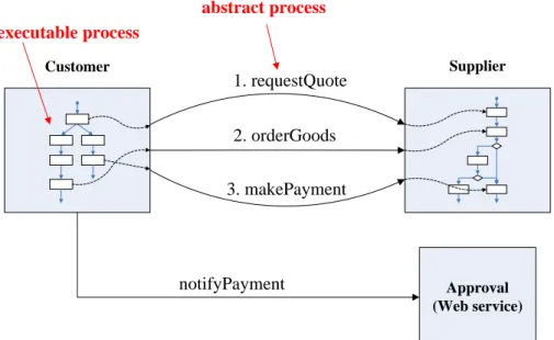
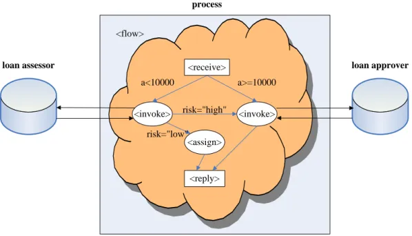
(16) Accordingly, WS-BPEL can be use to model complex composition and collaboration in a business process (Figure 2). abstract process executable process Customer. 1. requestQuote. Supplier. 2. orderGoods 3. makePayment. notifyPayment. Approval (Web service). Figure 2. WS-BPEL abstract and executable processes A business process defined by BPEL consists of activities and these activities can be basic or structured. Basic activities include <receive>, <invoke>, and <reply> operations. Briefly speaking, <receive> operation receives external message to start process, <invoke> represents the invocation of partner services, and <reply> sends the answer to the customer. Structured activities are used for managing the overall process flow. They include <flow>, <sequence>, <switch>, <assign>, and so on, which are used to realize potentially complex programming logic. The example in Figure 3 below is a process that handles loan request. A customer sends a request for a loan and waits for a respond whether the loan can be approved. If the requested amount is high, it will <invoke> a loan approver service for review. On the other hand, if the requested amount is lower than a given threshold, the process will <invoke> the loan assessor service to determine the risk. If the risk is considered low, the loan can be approved immediately and the <assign> activity is performed to prepare message for reply. Otherwise, the process will still send the application to the loan approver for review.. 7.
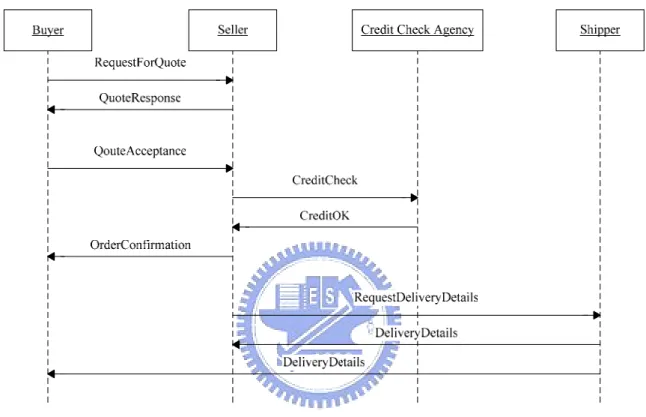
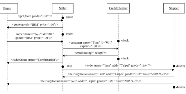
(17) process <flow> loan assessor. loan approver. <receive> a<10000 <invoke>. a>=10000 risk="high". <invoke>. risk="low" <assign>. <reply>. Figure 3. A loan application example in WS-BPEL. 2.3 WS-CDL WS-CDL (Web Services Choreography Description Language [CDL]) is another description language for service choreography proposed by W3C. Although WS-CDL is still under development currently as a working draft, it has been attracting wide attentions recently. Like WS-BPEL, WS-CDL is an XML-based language. Unlike WS-BPEL, however, it focuses on describing peer-to-peer collaborations among parties by defining, from a global viewpoint, their common and complementary observable behavior, where the ordered message exchanges collectively contribute to a common business goal [W3C b]. In other words, WS-CDL captures collaborative processes from a global perspective involving multiple Web services that participate in a choreography. In WS-CDL, a message exchange between roles or participants is called an interaction, which is the basic building block of service choreographies. WS-CDL also describes the channel for exchanging information. There are ordering structures similar to WS-BPEL such as sequential, parallel, and choice operators to combine other activities. Besides, WS-CDL also provides a work unit activity to describe the conditional or repeated executions. Figure 4 below shows an ordering goods choreography example in the form of an UML sequence diagram [Bruegge03]. There are four participants involved in this choreography: a buyer, a seller, a credit check agency, and a shipper. First, there are interactions between a 8.
(18) buyer and a seller to determine a price. After the buyer decides to order the goods when a quote is acceptable, the seller checks the credit of the buyer. If the buyer credit is acceptable, the seller will reply the buyer with order confirmation and then request a delivery data from the shipper. Finally, the shipper will inform the seller and the buyer about the delivery details. The CDL specification of this choreography is shown in Figure 5.. Figure 4. A choreography expressed as a UML sequence diagram <package name="BuyerSellerCDL" author="Steve Ross-Talbot" version="1.0" targetNamespace="www.pi4tech.com/cdl/BuyerSeller" xmlns="http://www.w3.org/2004/12/ws-chor/cdl" xmlns:bs="http://www.pi4tech.com/cdl/BuyerSellerExample-1"> ………… <choreography name="Main" root="true"> ………… <sequence> <interaction name="Buyer requests a Quote - this is the initiator" operation="requestForQuote" channelVariable="Buyer2SellerC" initiate="true"> <description type="description">Request for Quote</description> <participate relationshipType="BuyerSeller" fromRole="BuyerRoleType" toRole="SellerRoleType" /> <exchange name="request" informationType="RequestForQuoteType" action="request"> <description type="description">Requesting Quote</description> </exchange> 9.
(19) <exchange name="response" informationType="QuoteType" action="respond"> <description type="description">Quote returned</description> </exchange> </interaction> ………… </sequence> </choreography> </package>. Figure 5. A choreography example expressed in CDL Seeing that in the near future, service choreography will become common and crucial for Web service-based application development, in this thesis we choose WS-CDL as the reference model when describing collaborations involving multiple services, although abstract WS-BPEL process specification can also be used. We also use UML sequence diagrams frequently illustrate service choreographies. Our goal is to develop a specification language that is sufficient to supplement both WSDL and WS-CDL. In the next chapter, we motivate our work in this regard.. 10.
(20) Chapter 3. Motivation and Related Work. 3.1 Motivation We are interested in a picture larger than standards and mechanisms for service composition and coordination, that is, Web services-based software development (WSD). In a WSD project, the final system to be built consists of a number of services and other common components such as databases, client applications, legacy systems, etc. Each of the services may exist already or is under development, and may be developed and maintained by an external, independent organization or by the project development team themselves. In this sense Web services are a special but interesting class of software components, and WSD is similar to component-based development (CBD) [Fredriksson99] [D'Souza98], where components fabricated by independent parties can be assembled by others in unforeseen manner. Thus many issues related to CBD, in particular the use of COTS components in a development project, will also occur in WSD. Still, there are some differences between components and services. Most importantly, components are often static, reusable units that can be purchased and become the buyer’s assets. On the other hand, services are autonomous and maintained by the owner, and service “singletons” are also common, such as geography map services offered by specific vendor (Yahoo! Map or Google Map). Configuration management in such a decentralized environment becomes critical to ensure the consistency and quality of the composition. There are a number of roadblocks ahead towards the desirable open service market that also supports individual WSD projects without incurring excessive burden. To identify these obstacles, it is important to first characterize future development environment for WSD. Unlike traditional software projects that are initiated and managed within an enterprise, in WSD projects services are independently developed and maintained, with their own problem domains and design considerations in mind. In such a decentralized environment, to harness the heterogeneity exhibited by these external services and tailor them for current project need, developers need to carefully study and validate the interfaces and related documents about these services. Although the interfaces can be defined formally using WSDL, the behavioral aspects described in the associated documents may not be as rigorous [McIlraith03]. Those documents may not contain sufficient information describing the services, or worse, they may contain misleading or out-dated information, either by mistake or due to the mismatch 11.
(21) between documents and service implementation (versions). In addition, during runtime whether a given service behaves as it claims it would may not be easy to determine. Such a “trust problem” as presented in [Bertolino03] should be resolved for Web Services to be viable in the long run, but currently there is no suitable answer yet that are widely acceptable. Another equally important issue about WSD is the control and management of the WSD process. Due to the decentralized nature of a WSD project, the manager may not have sufficient control over the whole development process. The matter becomes more complicated when considering that different services developed either in-house or externally may be under different phases of construction with different plans or rate of progress. Generally speaking, careful configuration management for WSD projects is necessary in this case. However, techniques and mechanisms to ensure the consistence of services being composed for a specific project, and at the same time not to compromise the evolution and improvement of individual services, remain a challenge to be answered. Although we do not attempt to completely answer the WSD challenges discussed above, we do believe that by providing suitable mechanisms and tools, some of the problems can be relaxed. We propose to use scenarios as supplement information to describe the behavioral aspect of services. In short, a scenario describes a particular sequence of interactions between services and application instances using example messages. Unlike more comprehensive model-based specification techniques (e.g. Z) which attempt to describe software systems completely and mathematically, scenario-based specifications do not intend to cover all possible interaction sequences the system may exhibit. However, scenario-based approaches are more cost effective and easier to understand and to implement when compared to model-based specification techniques [Uchitel04]. Scenarios also fit nicely with common testing techniques [Tsai03b]. In fact, unit testing scripts can be regarded as simple scenarios in each of which there are only two entities: the client and the unit under testing. From this perspective, larger scenarios involving more than a couple of entities also provide useful information for integration testing. As test driven development has become one of the widely used development methodologies today, we believe infrastructure and tool support for service testing will be very beneficial for future WSD. In addition to the scenario-based specification, we will also design and implement a testing framework for Web services. Using the service type and scenario information, the 12.
(22) framework should generate appropriate test drivers and stubs to facilitate unit testing and integration testing, and should execute and monitor test cases in a distributed manner. Because one can choose to implement services incrementally and perform testing and obtain timely feedbacks, we believe our framework can be integrated in an overall WSD process nicely and contributes to its productivity. In the next chapter we first describe a scenario-based framework that we designed and developed with the motivations above in mind. Within the framework users first design and create service types which specify service interfaces that actual services need to support and conform to. Services are developed implementing one or more service types previously defined, and can be combined to form larger services. In particular, a service type can be associated with a set of scenarios so that implementing services (possibly by different people or groups) need to conform to the semantic constraints imposed by the scenarios. In addition, scenarios involving multiple services or applications can also be created and stored. These scenarios specify possible collaboration patterns and can help developers understand the design ideas and usage information of related services.. 3.2 Related Work As WSD grows important, many testing tools and techniques are developed continuously. The Web service testing framework and approaches proposed in [Tsai 02a] [Tsai 02b] and [Tsai03a] are some such examples. In particular, [Tsai02a] and [Tsai02b] propose to extend WSDL with information to facilitate testing, and to place supplement information such as test scripts for Web services inside UDDI so that verification can be performed when a Web service is checked in and out. Not surprisingly, the researchers developing the systems above also work on scenario-based modeling and testing framework for distributed (OO) systems [Tsai02c][Bai02] in a more general context. The central idea of their work is similar to ours. With additional, testing-based or scenario-based information associated with Web services, users gain more insights into the behavior of the services. In addition, automated verification to some extent becomes possible. However, their work essentially corresponds to unit testing in that scenarios and testing scripts are associated with individual Web services, and we are more interested in service choreography, especially when multiple participants are involved in potentially complex business processes. In fact, scenarios can coexist with and complement choreographies (e.g. 13.
(23) WS-CDL documents) and enhance their clarity yet permit easier test script generation. Furthermore, we are also interested in integrating scenario-based specification techniques with the overall WSD process, in particular unit testing and integration testing, and more importantly in requirements elicitation. To achieve this goal, our specification language is simplified to facilitate automated test driver and stub generation. In production of testing cases, Web Services use XML and SOAP to communicate on the internet; it is tedious to produce test cases for services. The data perturbation method proposed in [Offutt] makes use of grammar concepts to define message grammars. In the approach, real interaction messages are translated into test cases using date perturbation which works by modifying values in request messages and analyzing the response messages. It is intended that suitable test cases can be produced and web service testing can be proceeded easier and more automatic. However, [Offutt] focuses on peer-to-peer interactions and not provide further methods to support multilateral interactions. When facing more complex situations that, for example, are described as choreographies, the method needs to be extended. [Optimyz] provides a Web Services choreography testing solution based on WS-BPEL. After importing BPEL and WSDL files, user can start the business process testing which using the test data that can be specified using “Test Data Editor”. However, it is comparatively complicated and troublesome to specify each test data between Web services; especially, it requires a lot of participations. In comparison, our scenario-based approach is easier and can greatly reduce the efforts needed to design and implement testing strategies and save time for developing WSD processes.. 14.
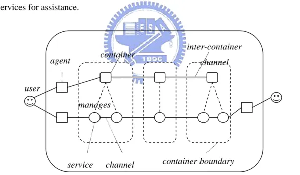
(24) Chapter 4. A Web Services Testing Framework. In this chapter we describe a Web services testing framework called WST. Before describing the system architecture, we first describe the underlying service-oriented infrastructure WST is based on.. 4.1 Service-Oriented Architecture The WST framework is based a service-oriented architecture we have been developing that supports dynamic service customization and composition. As depicted in Figure 6, the overall architecture is modeled as a service space that consists of agents and services communicating with each other through some kinds of channels (e.g. sockets, RMI, or SOAP). Agents are software entities that serve as intermediaries between users and services and may be equipped with GUIs. Services are network addressable software entities that function by processing requests through their interfaces. When processing requests a service may consult other services for assistance.. inter-container. container. agent. channel. user manages. service. container boundary. channel. Figure 6. Our service-oriented architecture Each service (instance) is associated with a service type. A service type describes the interface the service needs to implement. Service types are maintained in some registry services in a way similar to the UDDI registry in the Web Services architecture. We distinguish a special class of services, called service containers, to host other non-container services and govern their definition, instantiation, customization, composition, 15.
(25) and other lifecycle management. Specifically, a container is responsible of establishing suitable channels among the services it manages while respecting their requirements. Inter-container collaboration is needed when connecting services across container boundaries. In either case, service composition may involve complex, platform-specific managerial tasks such as setting up data or control flows properly. We have implemented several channel types based on sockets and Java RMI, as well as containers supporting both. Currently, we are also developing an SOAP-based channel type and the corresponding container using the Axis Web service container. Because in our implementation all services have the same primary interface, that is, a single point of contact that receives, interprets, and returns XML messages from clients, creating new channel types is straightforward. Specifically, for each channel type we only need to implement a container and associated contexts (as Java classes) to shield the communication details from managed services.. 4.2 WST Architecture The WST architecture is depicted in Figure 7. In the framework there are three basic components, that is, service container, scenario manager, and testing manager. Both the scenario manager and the testing manager are also services hosted in a container.. Figure 7. The WST architecture 16.
(26) The general usage of WST for WSD is as follows. Developers first develop and maintain scenarios thorough scenario manager during the requirements elicitation phase. In such a phase related requirement documentation and/or UML diagrams may also be created (use case diagrams, sequence diagrams, or other collaboration diagrams). Note that the design and creation of service types, can be done before, after, or in parallel to scenario development. When the set of scenarios become sufficient, the developers can request the testing manager to simulate the scenarios through automatically generated testing drivers and stubs, and verify and validate the results that are produced during the simulation. Under the development plan, the developers may choose to implement part of the services with higher priority and perform timely testing in an incremental manner. The testing manager can replace the stubs with actual services and perform testing. Such process is repeated until all system is developed. We describe each of the system modules in the following sections.. 4.3 Service Container As mentioned, service containers host and manage other non-container services in our service-oriented architecture. Containers themselves are also services so that they are subject to the same basic responsibility and privileges like other services. As a result, clients can query and manipulate services (instances) through the container that hosts them. In our WST case, when executing tests, the testing manager can create required services automatically (test drivers and stubs), or use those hand-crafted services by developers that are already set up in the container.. 4.4 Scenario Manager A scenario is usually referred to as a sequence of interactions between the user and the system and is usually used in software requirement design and analysis phases in conjunction with use cases. A scenario describes a concrete set of interactions and is usually used as an example for illustrating common case (Figure 8). Scenarios enhance requirements elicitation and system understanding by describing the communication patterns between users and systems. In this thesis, however, we consider in a more general case in which a scenario is an example sequence of interactions between the user and possibly more than one internal entities of the system.. 17.
(27) Figure 8. A scenario example The scenario manager in the WST architecture is responsible of storing and classifying scenarios. It maintains data structures to enhance classification and search. For proper separation of concerns, scenarios are organized hierarchically (e.g. [Tsai02]). As the example scenario below shows (Figure 9), a scenario can include other scenarios in its specification; hence increase the reusability and simplify scenarios design. <scenario name="buy/orderGoods/orderGoodsSuccess"> <ref name="creditCheckSuccess" path="buy/creditCheck/creditCheckSuccess"/> <role name="Seller" type="SellerType"/> <role name="CreditChecker" type="CreditCheckerType"/> ... <seq> <state name="check" role="CreditChecker"/> <call from="Seller" to="CreditChecker"> <customer name="Tom" id="001" expend="100"/> </call> ... <use scenario="creditCheckSuccess"> <role name="Seller" binding="Questioner"> <role name="CreditChecker" binding="VerifyAgency"> </use> ... <endcall from="Seller" to="CreditChecker"> <credit rating="accept"/> </endcall> <endstate name="check" role="CreditChecker"/> .... 18.
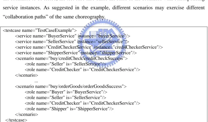
(28) </seq> </scenario>. Figure 9. The example using the scenario language. 4.5 Testing Manager Testing manager governs all the testing-related activities. When system developer hopes to use WST framework to test developing system, he/she can communicates with testing manager immediately. Testing manager contains two major components, namely the test case manager and the emulator manager. In WST, a test case is in fact a test suite where multiple tests can be performed. An example test case is shown in Figure 10, which contains more than one scenario. In addition to the scenarios to be tested, the test case also binds the roles of the scenarios with corresponding service instances. As suggested in the example, different scenarios may exercise different “collaboration paths” of the same choreography. <testcase name="TestCaseExample"> <service name="BuyerService" instance="buyerService"/> <service name="SellerService" instance="sellerService"/> <service name="CreditCheckerService" instance="creditCheckerService"/> <service name="ShipperService" instance="shipperService"/> <scenario name="buy/creditCheck/creditCheckSuccess"> <role name="Seller" is="SellerService"/> <role name="CreditChecker" is="CreditCheckerService"/> </scenario> ... <scenario name="buy/orderGoods/orderGoodsSuccess"> <role name="Buyer" is="BuyerService"/> <role name="Seller" is="SellerService"/> <role name="CreditChecker" is="CreditCheckerService"/> <role name="Shipper" is="ShipperService"/> </scenario> </testcase>. Figure 10. A test case example Test drivers and stubs that are essential during unit testing and integration testing. A driver simulates a client that calls the system under test or its subsystems/components. A test stub, on the other hand, simulates a component or subsystem that has not been developed yet. In our framework, both drivers and stubs are supported uniformly by emulators. An emulator can act as both test driver and/or test stub. As mentioned, throughout a WSD process some of the services may be under construction and not available for testing. The WST framework 19.
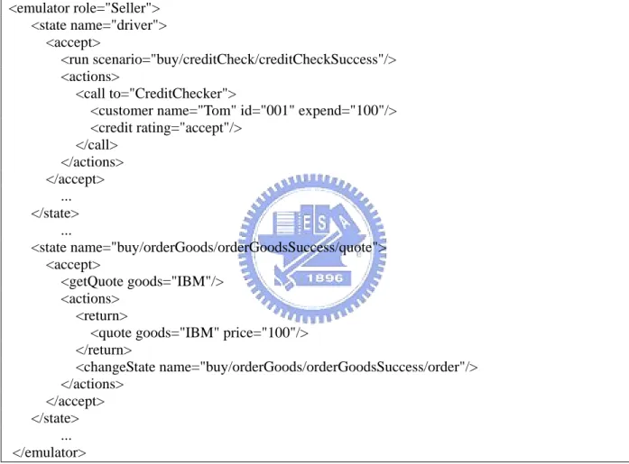
(29) allows this situation and can use emulators to substitute unfinished roles or participants. At this time, the emulator acts a stub to receive messages or invoke other services. An emulator also can substitute a driver. It invokes roles or participants in sequence when it receives a starting message. In WST, an emulator is generated automatically from multiple scenarios and is stored and classified by the emulator manager. Figure 11 is an example of emulator. The language for describing emulators will be further illustrated in the next section. <emulator role="Seller"> <state name="driver"> <accept> <run scenario="buy/creditCheck/creditCheckSuccess"/> <actions> <call to="CreditChecker"> <customer name="Tom" id="001" expend="100"/> <credit rating="accept"/> </call> </actions> </accept> ... </state> ... <state name="buy/orderGoods/orderGoodsSuccess/quote"> <accept> <getQuote goods="IBM"/> <actions> <return> <quote goods="IBM" price="100"/> </return> <changeState name="buy/orderGoods/orderGoodsSuccess/order"/> </actions> </accept> </state> ... </emulator>. Figure 11. An emulator as both a test driver and stub The emulator manager is capable of translating scenarios into emulators, and maintains their identities and storage. The test case manager maintains test cases that are created by developers. In short, a test case describes the set of scenarios to be tested and the set of system components, either emulators or actual implementations, in those scenarios. As a result, the main job of the testing manager becomes the execution and monitoring of test cases.. 20.
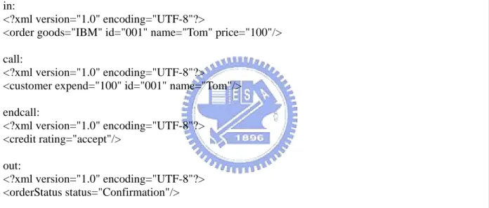
(30) 4.6 Testing Execution and Monitoring WST can perform unit testing for individual services as well as integration testing for business processes. Unit testing helps system developers understand the semantics of individual services and verify their implementation. Integration testing help developers verify business processes for complicated collaborations or Web services choreography, and can assist Web Services-based application development across organizations boundaries. WST will logs relative interactions in log files at the same time. Every role has own log file to record corresponding communications. Figure 12 is a log file of the role to illustrate messages and order of interactions. Our can analyze these log files to verify whether the processes of scenarios are correct or not. in: <?xml version="1.0" encoding="UTF-8"?> <order goods="IBM" id="001" name="Tom" price="100"/> call: <?xml version="1.0" encoding="UTF-8"?> <customer expend="100" id="001" name="Tom"/> endcall: <?xml version="1.0" encoding="UTF-8"?> <credit rating="accept"/> out: <?xml version="1.0" encoding="UTF-8"?> <orderStatus status="Confirmation"/> …. Figure 12. An example of log files. 21.
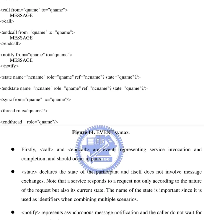
(31) Chapter 5. Scenario-Based Specification. To describe Web Services-based applications using scenarios, the scenarios should be properly organized, classified, and managed. In order to achieve such divide-and-conquer goal, we define a supporting XML-based, scenario-based specification language in this chapter.. 5.1 Language Description We consider a Web services-based system consists of multiple interacting Web services and other subsystems such as client applications, databases, etc. For brevity we refer to the services and sub-systems as components that make up the system. Through some client applications, users can interact with the system during a session by issuing requests and receiving replies. Upon receiving a request, the system may initiate a chain of reactions involving a particular pattern of message exchanges among the constituent components. The message exchange pattern depends on the nature and content of the request as well as the current system state, and is not necessarily in a simple sequential order; that is, some exchanges may occur concurrently because the participating components each may has its own control flow. Based on the system model above, we describe the behavior of the system using a collection of scenarios. Each scenario represents one particular message exchange pattern using example (but meaningful) messages. The syntax for each scenario is depicted in Figure 13, where we use informal but commonly used representation for syntax definition: <scenario name="ncname"> <role name="qname" type="qname"?/>+ <seq> EVENT+ </seq> </scenario>. Figure 13. Syntax of scenarios In our language, the definition of a scenario is divided into two parts. First the roles of participants in the scenario is declared, followed by a sequence of events each may indicate state change or an interaction between two participants. There are some basic types of events. Figure 14 shows EVENT syntax in the scenario language.. 22.
(32) EVENT : <call from="qname" to="qname"> MESSAGE </call> <endcall from="qname" to="qname"> MESSAGE </endcall> <notify from="qname" to="qname"> MESSAGE </notify> <state name="ncname" role="qname" ref="ncname"? state="qname"?/> <endstate name="ncname" role="qname" ref="ncname"? state="qname"?/> <sync from="qname" to="qname"/> <thread role="qname"/> <endthread. role="qname"/>. Figure 14. EVENT syntax. z. Firstly, <call> and <endcall> are events representing service invocation and completion, and should occur in pairs.. z. <state> declares the state of the participant and itself does not involve message exchanges. Note that a service responds to a request not only according to the nature of the request but also its current state. The name of the state is important since it is used as identifiers when combining multiple scenarios.. z. <notify> represents asynchronous message notification and the caller do not wait for message receiver’s response.. z. In contrast, <sync> represents a synchronization step and its objective is to align the execution progress of two participants. Note that although synchronization mechanisms is common among various concurrent programming languages and systems (e.g. join operations or rendezvous), their use is not common for ordinary Web services except for services that orchestrate other services (such as within a WS-BPEL workflow). As will become clear later, in our language <sync> is primarily for testing purpose and is considered outside the responsibility of ordinary Web services. 23.
(33) z. Finally, in a complex choreography, a participant may initiate actions upon receiving a message. Normally all events following the message reception (by <call> or <notify> from another participant) and originated from the participant are consider the actions to be taken by that participant (in the order specified), until the event that indicate the end (by <endcall> or other incoming events). In the case concurrent groups of actions need to be initiated, <thread> and <endthread> suit the purpose.. Figure 15. Scenario example We expand the above-mentioned ordering goods choreography example in figure 15. First, there are interactions of determining a price between a buyer and a seller, and then buyer send a synchronous signal to credit checker. After credit checker receives the synchronous signal, it notifies a message to the seller and then sends a synchronous signal to buyer similarly. The buyer decides to order the goods when a quote is acceptable, and the seller then must to checks the buyer credit rating. If the buyer credit rating is ok, the seller will responds order confirmation and then requests a delivery data from the shipper. Finally, the shipper informs the seller and the buyer of the delivery details.. 24.
(34) To describe the scenario using our language, first roles should be defined. In this example, there are four roles in the choreography and each role has distinct name. As Figure 16, they are individually buyer, seller, creditchecker, and shipper. <scenario name="buy/orderGoods/orderGoodsSuccess"> <role name="Buyer" type="BuyerType"/> <role name="Seller" type="SellerType"/> <role name="CreditChecker" type="CreditCheckerType"/> <role name="Shipper" type="ShipperType"/>. Figure 16. Roles In choreography, multiple interactions are integrated and combined among whole roles for communication. An interaction stands for information exchanged between two roles. Figure 17 is the first interaction part of our example. The buyer sends request messages to the seller for quotes, and then the seller respond messages of prices. <state> and <endstate> represent separately the seller initial state and end state of this interaction. <seq> <state name="quote" role="Seller"/> <call from="Buyer" to="Seller"> <getQuote goods="IBM"/> </call> <endcall from="Buyer" to="Seller"> <quote goods="IBM" price="100"/> </endcall> <endstate name="notify" role="Seller"/>. Figure 17. Service invocation example Figure 18 is an example of synchronization and notification. The buyer sends a synchronous signal to wake credit checker up. After the credit checker finishes <notify> event, it goes back a synchronous signal to the buyer. <sync from="Buyer" to="CreditChecker"/> <state name="notify" role="Seller"/> <notify from="CreditChecker" to="Seller"> <invite method="inquire"/> </notify> <endstate name="order" role="Seller"/> <sync from="CreditChecker" to="Buyer"/>. Figure 18. Synchronization and notification. 25.
(35) The fragment below (Figure 19) is a thread example to illustrate active events. The seller has a sequence of active events which invokes the shipper and obtains its response between <thread> and <endthread>. <thread role="Seller"/> <call from="Seller" to="Shipper"> <order name="Tom" addr="Taipei" goods="IBM"/> </call> <endcall from="Seller" to="Shipper"> <deliveryDetail name="Tom" addr="Taipei" goods="IBM" time="2005-9-25"/> </endcall> <endthread role="Seller"/>. Figure 19. Threads The scenario language will assist us to design and analysis of system requirement. The language is capable of describing complex scenarios in choreography. A complete scenario description which uses our scenario language is shown in Figure 20. <scenario name="buy/orderGoods/orderGoodsSuccess"> <role name="Buyer" type="BuyerType"/> <role name="Seller" type="SellerType"/> <role name="CreditChecker" type="CreditCheckerType"/> <role name="Shipper" type="ShipperType"/> <seq> <state name="quote" role="Seller"/> <call from="Buyer" to="Seller"> <getQuote goods="IBM"/> </call> <endcall from="Buyer" to="Seller"> <quote goods="IBM" price="100"/> </endcall> <endstate name="notify" role="Seller"/> <sync from="Buyer" to="CreditChecker"/> <state name="notify" role="Seller"/> <notify from="CreditChecker" to="Seller"> <invite method="inquire"/> </notify> <endstate name="order" role="Seller"/> <sync from="CreditChecker" to="Buyer"/> <state name="order" role="Seller"/> <call from="Buyer" to="Seller"> <order name="Tom" id="001" goods="IBM" price="100"/> </call> <state name="check" role="CreditChecker"/> <call from="Seller" to="CreditChecker"> <customer name="Tom" id="001" expend="100"/> </call> <endcall from="Seller" to="CreditChecker"> <credit rating="accept"/> 26.
(36) </endcall> <endstate name="check" role="CreditChecker"/> <endcall from="Buyer" to="Seller"> <orderStatus status="Confirmation"/> </endcall> <endstate name="ship" role="Seller"/> <state name="deliver" role="Shipper"/> <thread role="Seller"/> <call from="Seller" to="Shipper"> <order name="Tom" addr="Taipei" goods="IBM"/> </call> <endcall from="Seller" to="Shipper"> <deliveryDetail name="Tom" addr="Taipei" goods="IBM" time="2005-9-25"/> </endcall> <endthread role="Seller"/> <thread role="Shipper"/> <notify from="Shipper" to="Buyer"> <deliveryDetail name="Tom" addr="Taipei" goods="IBM" time="2005-9-25"/> </notify> <endthread role="Shipper"/> <endstate name="deliver" role="Shipper"/> </seq> </scenario>. Figure 20. Complete scenario. 5.2 Stub and Driver Generation The syntax of the scenario language is designed to be as simple as possible, so that the choreography among participants is just a sequence of events. However, the sequence is interpreted differently from the perspective of each individual service. In particular, a service only concerns the events that directly involve the service itself and discard the rest, which is what the semantics of the scenario language is based on. Specifically, based on a collection of scenarios, we can approximate each component using an emulator. As depicted in Figure 21, an emulator consists of multiple states, and each state is further divided into multiple sections each corresponding to one distinct input message. Each such section, which we refer to as action block, in turn contains a sequence of actions.. 27.
(37) Emulator State. Message <getQuote goods="IBM"/>. Action Block. Message Action Block. Message. <return> <quote goods="IBM" price="100"/> </return> <changeState name="buy/orderGoods/ orderGoodsSuccess/order"/> .... Action Block . . .. State. . . .. Figure 21. Structure of an emulator The abstract syntax for emulator construct is shown Figure 22. Actions include several various elements and these are listed in Figure 23. <emulator> <state name="qname"> <accept> MESSAGE <actions> ACTION* </actions> </accept>+ </state>+ </emulator>. Figure 22. Emulator syntax z. <call> represents a normal procedural invocation: when performing a call action the emulator will “invoke” the target service as indicated in the <call> action with given 28.
(38) input message, and wait for response message which in turn is checked against the expected output message in the <call> action. z. <return> action represents the end of the invocation originated from the input message that started the action block.. z. <changeState> action will change the state of the emulator.. z. <notify> action send a message to the target participant without waiting for reply.. z. <thread> and <endthread> occur in pairs with actions enclosed in between (however <thread> and <endthread> cannot be nested further). As the names suggest, the sequence of actions within a thread is executed in order, but different threads can execute concurrently.. z. <wait> lets the emulator wait until a <wakeup> message from the expected participant arrives.. ACTION: <return> MESSAGE </return> <call to="qname"> IN_MESSAGE OUT_MESSAGE </call> <notify to="qname"> MESSAGE </notify> <wakeup to="qname"/> <wait/> <changeState name="qname"/> <thread> ACTION+ </thread>. Figure 23. Action syntax Emulators have straightforward operational semantics. An emulator can be in one of the designated states. Upon receiving an input message, the emulator looks up the corresponding 29.
(39) action block identified by the input message, perform the actions one by one, and finally may change to a new state. The structure of an action block is illustrated in Figure 24.. Figure 24. Action structure Emulators are combination of test stubs and test drivers that are commonly used for integration testing. When testing a large system that consists of multiple subsystems, instead of developing all subsystems completely and then performing a “big-bang” integration testing, more incremental integration testing strategies are often used, so that each subsystem can be developed concurrently, possibly with different priorities and timelines. During integration testing, to test a given subsystem, a test driver is needed to drive the interaction with the system under test. If the subsystem is yet to be developed, a test stub is created and used instead to simulate its behavior. Ideally, the stub should appear indistinguishable from the actual subsystem. To simulate test drivers, we distinguish a special state, i.e. “driver” state, from other states in an emulator. The action block for the “driver” state is consider the driver part of the emulator, so that when the emulator starts execution, this driver part is performed 30.
(40) spontaneously without waiting for an input message. Figure 25 is an emulator example to contain a stub and a driver. When state name is “driver”, state sections are stored relative information of drivers. Or else they are stored some interactions of a stub. <emulator role="Seller"> <state name="driver"> <accept> <run scenario="buy/creditCheck/creditCheckSuccess"/> <actions> <call to="CreditChecker"> <customer name="Tom" id="001" expend="100"/> <credit rating="accept"/> </call> </actions> </accept> ... </state> ... <state name="buy/orderGoods/orderGoodsSuccess/quote"> <accept> <getQuote goods="IBM"/> <actions> <return> <quote goods="IBM" price="100"/> </return> <changeState name="buy/orderGoods/orderGoodsSuccess/order"/> </actions> </accept> </state> ... </emulator>. Figure 25. Emulator example With the operational semantics of the emulator language outlined above, the semantics of our scenario language is defined via an unambiguous mapping from a set of scenarios to a set of emulators (Figure 26). Scenarios describe the whole interactions among for all roles or participants. But the job of an emulator is to serve as the application driver or to substitute an unfinished role or participant. We can collect relative scenarios and integrate events of a particular role to generate a corresponding emulator.. 31.
(41) Figure 26. An emulator is generated by multiple scenarios The semantics of our scenario-based specification language is completed when the semantics of emulators is defined and the translation from a set of scenarios to a set of emulators is defined. Figure 27 outlines the algorithm in pseudo code that performs such a mapping. Algorithm: in: S : scenario set role : role name out: E : configuration of emulator func genEmulator (S : scenario set, role : role name) { E = empty for each scenario s in S { st : current state ac: action block of current state istack: put intput and return, initiate is empty cstack: put call and endcall, initiate is empty temp: store ac point temporarily when thread for each event e in s such that roleName = role, to = role, or from = role { case e = state(name, role) : if ac is null then E.append(st) st = (s, name) 32.
(42) case e = state(name, role, s', st') : if ac is null then E.append(st) st = (s', st') case e = endstate(name, role') : ac.append(changeState, s, name) case e = endstate(name, s', st') : ac.append(changeState, s', st') case e = call(role, to, msg) : if ac is null then begin st = (driver) ac = st.createActionBlock(s.name) cstack.push(e) end if ac is not null then cstack.push(e) case e = call(from, role, msg) : if istack is empty then begin ac = st.createActionBlock(msg) istack.push(from) end if istack is not empty skip e case e = endcall(role, to, msg) : cstack.pop(): e' if e.to' = to ac.append(call, e'.msg, msg) if e.to' != to begin skip e cstack.push(e') end case e = endcall(from, role, msg) : istack.pop(): from' if from' = from then ac.append(return, msg) if from' != from then begin skip e istack.puch(from') end case e = notify(role, to, msg) : if ac = null then begin st = (driver) ac = st.createActionBlock(s.name) ac.append(notify, to, msg) end if ac != null then ac.append(notify, to, msg) case e = notify(from, role, msg) : 33.
(43) if ac is not null E.append(st) ac = st.createActionBlock(msg) case e = sync(from, role) : if st = null then begin st = (driver) ac = st.createActionBlock(s.name) end ac.append(wait, from) case e = sync(role, to) : ac.append(wakeup, to) case e = thread(role) : tmp = ac ac = createThreadBlock() case e = endthread(role) : threadBolck = ac ac = tmp ac.append(threadBlock) } E.append(st) } return E }. Figure 27. Enumerator generation from scenarios. 34.
(44) Chapter 6. System Design and Implementation. We outline the design of our system and some details about implementation in this chapter. As mentioned in chapter 4, WST is a testing framework for Web services consists of three basic components: service container, scenario manager, testing manager. In Figure 28 we outline our system implementation. When a system developer requests testing manager to test or verify for a business process, testing manager will respectively collect related information from service container, scenario manager, test case manager, and emulator manager, and then execute the testing processes and verify the results based on the generated log files.. Developer. Test Cases. Test Case Manager. Emulators. Emulator Manager. Testing Manager. Test. Scenario Manager. Testing Processes. Service Types Service Container Instances. Scenarios. Figure 28. Overview of our system implementation Service-related information can be obtained from the service container. It includes several components. Figure 29 shows the class diagram of the service container in our system. z. ServiceTypes: A service type is just the service interface to describe functionality of service role. A ServiceTypes stores and manages these service types and supports corresponding queries.. z. ServiceInstances: A service instance is a real Web service which can be invoked by client or other Web service. When service instances finish developing, it will be managed by a ServiceInstances object. 35.
(45) z. Services: ServiceContainer can deploy instances of ServiceInstances to publish services which are managed by Services. In other word, Services control services which have been deployed. <<介面>> <<interface>> IServiceContainer +deploy(). <<介面>> <<interface>>. ServiceContainer. <<介面>> <<interface>> IServiceInstances +getInstance(). <<介面>> <<interface>>. ServiceInstances. IServices +getService(). Services. IServiceTypes +getServiceType(). ServiceTypes. Figure 29. Service container class diagram Scenario manager is used to store and classify scenarios. Figure 30 below is the class diagram containing classes related to scenario management. A Scenarios object is itself a service hosted in a container to manage scenarios described in our scenario-based specification language.. Figure 30. Scenarios class diagram Testing manager controls activities related to testing. When system developer hopes use WST framework to test developing system, he can communicates with testing manager. 36.
(46) immediately. Testing manager contains two sub-components, namely test case manager and emulator manager. <<介面>> <<interface>> ITestingManager +getContainer() +getScenarios() +getTestCases() +getEmulators(). <<介面>> <<interface>> IEmulators +getEmulator() +addEmulator(). Emulators. TestingManager. <<介面>> <<interface>> ITestCases +getTestCase() +addTestCase(). 1 *. 1. TestCases. *. TestCase. Emulator. Figure 31. Testing Manager class diagram Figure 31 is the class diagram for testing manager. In the diagram, TestCases and Emulators are also services hosted as containers and classify and manage TestCase and Emulator object.s With TestCases and Emulators, it is easy to acquire testing essential information and execute verification. z. TestCases: A TestCase structure is a test suite. Besides recording testing scenarios, it also binds scenario roles and corresponding service instances. We can acquire particular TestCase by getTestCase() and increase new TestCase by addTestCase() method.. z. Emulators: An Emulator is generated from multiple scenarios and stored and classified by Emulators. Emulators is similar to TestCases. We can acquire particular Emulator by getEmulator() and increase new Emulator by addEmulator() method.. Besides TestCases and Emulators, TestingProcesses is responsible of managing individual testing processes. When application developer executes testing for a test case, TestingProcesses will create a new process which uses ID as its identification and operate 37.
(47) runTest() method (Figure 32). In other words, our WST system can test or verify for multiple test cases at the same time and let whole testing systems are more forceful.. Process 1 runTest() Testing Manager. Testing Processes. Processes. Process 2. ‧ ‧ ‧ Process n. Figure 32. Testing processes WST can assist Web Services-based application development across organizations boundaries. For repeatable functionality, it will quote the same scenario specification to reduce complexity greatly. Due to the assistance of the WST, application system developer can focus on the system integration based on interface. It also can reduce coupling between web services to lessen further unnecessary mistakes and save developing time.. 38.
數據
+7

相關文件
Persistent Connections (HTTP 1.1):HTTP 1.1改進 了HTTP 1.0 的缺點,藉由PersistentConnections減 少TCP connections,以增加WEB Server
使用人工智慧框架基礎(Frame-based)的架構,這些努力的結果即為後來發展的 DAML+OIL。DAML+OIL 是 Web Resource 中可以用來描述語意的 Ontology 標 記語言,它是以 W3C
除了酒店、交通及景點,還
(A) File Transfer Protocol, FTP (B) Electronic Mail, E-Mail (C) World Wide Web, WWW (D) Word Wide Web,
RMI,及 DCOM 這些以專屬 binary 格式傳送資料所不及之處,那 就是對程式語言、作業平台的獨立性--由於是純文字 XML 格 式,
服務提供者透過 SOAP 訊息將網路服務註冊在 UDDI 中,服務需求者也可以透 過 SOAP 向服務仲介者查詢所需的 Web Service 並取得 Web Service 的 WSDL 文件,2.
Web 伺服器 Internet information services 6 相關應用工具 SQL Server 2005 Analysis services. SQL server business intelligence development Studio Visual
1998 年 2 月,XML 建議標準提出,是目前通用的 XML1.0 版 本標準,XML 的規格便是由 W3C XML 工作群維護並負責增修 跟調整的工作。基本上 SGML、HTML
