Research Express@NCKU - Articles Digest
Research Express@NCKU Volume 10 Issue 9 - October 2, 2009 [ http://research.ncku.edu.tw/re/articles/e/20091002/1.html ]
Tunable grating based on stressed liquid crystal
Andy Ying-Guey Fuh
*, Shih-Wei Ko, Tsung-Hsien Lin
Department of Physics, Institute of Electro-optical Science and Engineering, NCKU [email protected]
Optics Express, Vol.16, Issue 3, pp.2062-2067 (2008)
I
t is known that a typical grating can diffract an incident light into various- order beams. Gratings based on liquid crystal (LC) have attracted considerable interest owing to their high birefringence and sensitivity to an applied field, and possess considerable potential for application in displays, photonics and optical communications. In this paper, we report a new LC grating using the newly developed stressed liquid crystals (SLCs).The concentration of polymer used in a SLC device is between that in polymer dispersed liquid crystals (PDLCs) and polymer stabilized liquid crystals (PSLCs).
Typically, PDLCs and PSLCs contain polymer concentrations at ~30–50 wt%,
and <10 wt%, respectively. These devices are operated based on the light scattering effect, and required to apply a high electric field. Yet, the SLC device can be operated not only applying a voltage, but shearing the substrate. Fast response and large phase retardation can be achieved using a SLC grating. Both the intensity and polarization of the diffracted beams can be controlled.
The SLC films were fabricated by homogeneously mixing a nematic liquid crystal LC (85 wt%) with a Norland optical adhesive NOA65 (15 wt%) (as a photo-polymerizable monomer). The LC employed was K15 (Merck), which has an ordinary refractive index of no= 1.5309, and a birefringence of ∆n =0.1754. Drops of homogeneously mixed K15-NOA65 compound were then sandwiched between two indium-tin-oxide (ITO)- coated glass slides (25 μm) to produce a sample. Before UV exposure, the cell was heated to T=120°C, at which LCs are isotropic. Then, the cell maintained at 120˚C, was exposed under an unpolarized UV light (365 nm) through a grating mask (spacing is 50 μm). Curing UV intensity was 12 mW/cm2 and the exposure time was 25 minutes [Fig. 1(a)]. Figures 1(b)-left and 1(b)-right illustrate the randomly and uniformly aligned LC domains dispersed in the polymer network before and after the sample was sheared, respectively. During shearing, one substrate of the SLC device was fixed, and the other substrate was sheared into various lengths (Fig. 1(b)-right).
Fig. 1 (a) Setup for UV-curing a sample through a grating mask; (b) schematic representation of the cell structure before (left) and after (right) shearing.
Notably, observations of SLC grating were performed under an optical polarized microscope (OPM). All
1 of 4
Research Express@NCKU - Articles Digest
cells were measured by applying a He-Ne laser (632 nm) as the probe beam at room temperature. Shearing length (Lshear) of the SLC grating was controlled by a micro-screw (precision is 1μm), and the shearing direction was along the grating vector.
Fig. 2. Images of an SLC grating under a polarized optical microscope before and after shearing (50 μm); P, polarizer; A, analyzer.
The images of an SLC grating under an OPM before and after shearing are presented in Fig. 2. The regions in a cell corresponding to the opaque and transparent ones of the photo-mask after UV exposure are enclosed by red- and green-dotted lines (Fig. 1), respectively. The UV exposed regions (green-dotted lines) formed a polymer-rich scattering conformation, and stayed at a scattering state after stressing due to the formed dense polymer network (Fig. 2). This result is reasonable since monomer concentration is getting lower in transparent regions than that in opaque regions during polymerization. This results in the fact that some monomers in the opaque regions diffuse towards adjacent transparent regions to equilibrate the monomer concentration across the sample, and form dense polymer networks in the transparent regions.
Then, UV light was then scattered by the formed polymer networks in the transparent regions into the adjacent opaque regions where light polymer networks formed by side-scattered UV light. Due to the diffusion of monomers, a dark line formed in the center of the opaque regions, where LCs were rich and well aligned along the grating vector. Under a crossed-polarizer OPM, the region with well-aligned LCs appeared dark [Fig. 2(a)]. After stressing, the dark line widened [Fig. 2(b)], meaning that more LC-polymer
composites were aligned toward the grating vector during stressing [Fig. 1(b)]. Figures 2(c) and 2(d) present the images of the same conformation under a parallel-polarizer OPM. The regions with well-aligned LCs became bright, indicating that the LC alignment in opaque regions can change by stressing [Fig. 1(b)], and such an alignment change after stressing can be used to control the phase difference of an incident beam through the SLC grating. Like a typical LC device, a SLC grating can be controlled also by applying a voltage.
Therefore, a SLC grating can be modulated by shearing or by applying a voltage to tune diffracted beam intensity and polarization demonstrated below.
2 of 4
Research Express@NCKU - Articles Digest
Fig. 3. Diffraction patterns of an SLC grating observed under, (a) P//A, (b) P⊥A. before stress (upper) and after shearing (bottom) with a Lshear
=50μm; P, polarizer; A, analyzer.
Fig. 4. Variation of the zero- and first-order diffraction intensities with shearing length Lshear under a cross-polarizer condition with the polarizer axis at an angle of ~45˚ relative to the grating vector.
Figure 3 shows the diffraction patterns of an SLC grating before and after shearing (Lshear =50 μm) under parallel-polarizer (Fig. 3(a)) and crossed-polarizer (Fig. 3(b)). The polarization of the probe-beam was parallel to the grating vector. Figure 4 plots the measured intensities of the zero- and first-order diffractions by shearing various lengths under the cross-polarizer condition with the polarizer axis at an angle of ~45˚
relative to the grating vector. Each of these two orders is seen to be modulated as the phase retardation varied by shearing lengths (Lshear).
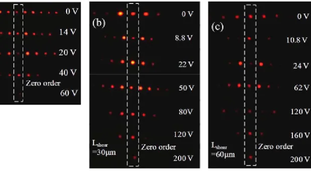
Diffraction patterns of the SLC grating were then observed by applying AC voltages with the sample sheared a length. The measurement was also performed under a cross-polarizer condition with the polarizer axis making an angle of ~45˚ relative to the grating vector. The diffraction patterns of SLC grating devices under different shearing distances and applying voltages are shown in Fig. 5. Figure 6 presents the measured relations between the first-order diffraction efficiency and applied voltage under the parallel- polarizer condition as the sample was sheared from 0–60 μm. The diffraction efficiency (η) is defined as η=Id / Ii, where Ii and Id are intensities of the probing and diffraction beams. Similar to the results obtained with the sheared sample (Fig. 4), a SLC grating can also be modulated electrically. Notably, the modulation effect becomes obvious as shearing length increases.
Fig. 5. Diffraction patterns of an SLC grating sheared with a length Lshear of (a) 0 μm, (b) 30 μm, and (c) 60 μm under the application of various AC voltages. Measurements were performed under the cross- polarizer condition with the polarizer axis at an angle of ~45˚ relative to the grating vector.
Polarization of the first-order diffraction with the sample stressed was measured. The measurement was performed with the polarizer axis parallel to the grating vector, and the analyzer axis was rotated with the polarizer. Figure 7 presents measurement results. Due to the phase variation in the opaque regions under stressing, the polarization of the first-order beam can be controlled with shearing the sample.
3 of 4
Research Express@NCKU - Articles Digest
Fig. 6. Variation of the first-order diffraction intensity with the application of AC voltages under a parallel-polarizer condition with the polarizer axis at an angle of ~45˚ relative to the grating vector.
Fig. 7. Variation of the first-order beam with sample under stress. Measurements are performed with the polarizer axis parallel to the grating vector , and rotating the analyzer axis.
In conclusion, this study presents a novel SLC grating that can be modulated by shearing a length or applying an AC voltage. Both the intensity and polarization of diffracted beams from a SLC grating can be tuned. The device capable of tuning the intensity and/or polarization of diffracted beams is highly
demanded in various optical systems. Thus, SLC gratings have a good potential for practical applications.
4 of 4