Security Monitoring around a Video Surveillance Car with a Pair of Two-camera Omni- directional Imaging Devices
Pei-Hsuan Yuan
Institute of Multimedia Engineering National Chiao Tung University
Hsinchu, Taiwan [email protected]
Kuo-Feng Yang
Institute of Information Science and Engineering
National Chiao Tung University Hsinchu, Taiwan [email protected]
Wen-Hsiang Tsai Department of Computer Science
National Chiao Tung University Hsinchu, Taiwan [email protected]
Abstract—3D vision-based methods for security monitoring around a video surveillance car using a pair of newly-designed two-camera omni-directional imaging devices affixed on the car roof are proposed. The methods may be used for monitoring the neighboring area and any passer-by approaching the car. First, the design principle of the new two-camera omni-directional imaging device is described. Each device consists of two omni- cameras with their optical axes vertically aligned. Then, a new analytic technique of 3D data acquisition using the camera system based on the use of the pano-mapping method and the rotational invariance property of the omni-camera is proposed.
A technique for constructing top-view images and merging them into wider-area integrated ones as well as a technique for constructing perspective-view images of any directions are also proposed. Furthermore, a method for detecting a suspicious passer-by around the car automatically, locating his/her position around the car, and computing his/her body height is proposed as well. Good experimental results show the feasibility of the proposed methods.
Keywords-video surveillance; omni-camera pair; omni-image;
3D data acquisition; passer-by detection and location I. INTRODUCTION
Video surveillance systems have been used widely, not only to prevent crimes but also to improve automation works for human beings’ welfare. In order to increase the mobility of video surveillance systems, video surveillance cars have been used in recent years. Applications of such cars include dynamic monitoring of outdoor events, assistance to safe driving, surveillance of dangerous environment changes, etc.
In this study, in order to enlarge the fields of view (FOV’s) of traditional cameras and increase the mobility of the surveillance area to meet various video surveillance applications, it is desired to design a wide-area vision-based surveillance system on the roof of a video surveillance car using a pair of two-camera omni-directional imaging devices, which has the following capabilities:
1. constructing a top-view image of the surrounding area of the surveillance car;
2. constructing a perspective-view image of any direction specified by the user; and
3. detecting any suspicious passer-by automatically and measuring his/her location and height.
Video surveillance has been widely investigated in the past decade. Most research works are about indoor surveillances.
Onoe et al. [1] and Mituyosi et al. [2] conducted researches for such a purpose using omni-cameras. A video surveillance system using multiple omni-directional cameras was proposed by Morita et al. [3]. Some related research works used omni- camera pairs with hyperboloidal-shaped reflective mirrors, such as Koyasu et al. [4] and Ukida et al. [5]. Furthermore, a method that reconstructs the 3D data of static nearby vehicles by a mobile robot using a stereo omni-directional camera (a two-mirror omni-directional imaging device) was proposed by Meguro et al. [6]. However, the proposed method is time- consuming for 3D space reconstruction, and this is undesirable in real-time video surveillance.
In this study, the topic of security monitoring around a video surveillance car is investigated. We design an imaging device which is composed of two catadioptric cameras longitudinally and coaxially aligned, and use a pair of such imaging devices to derive stereo environment information.
One device is affixed to the left front part of the roof of the video surveillance car and the other device to the right rear part of the car roof. A new technique to obtain a passer-by’s location and height is implemented in this study, which was not found in previous works. Furthermore, we use the pair of two-camera omni-directional imaging devices to take images to compute 3D data and use them to construct top- and perspective-view images in any direction for convenient and real-time display of the surrounding environment.
In the remainder of this paper, the configuration of the proposed system is described in Section II, the design of the camera system and the proposed technique for computation of 3D data are described in Section III. Monitoring of a passer-by, including computation of his/her location and height, is described in Section IV. Generation of top- and perspective- view images is described in Section V, followed some experimental results and conclusions in Sections. VI and VII, respectively.
II. SYSTEM CONFIGURATION
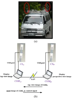
As illustrated in Fig. 1, the proposed system includes a video surveillance car (see Fig. 1(a)), a pair of two-camera omni-directional imaging devices CSA and CSB, and two laptop computers COMA and COMB (see Fig. 1(b)). Each two- camera omni-directional imaging device is controlled by a laptop computer, and a local network was designed to connect the two computers. Specifically, COMA is used to display the top-view image of the surrounding area of the video
surveillance car, and COMB to display the perspective-view images of specified view directions out of the car. To achieve this, COMB transforms the omni-images gathered from CSB
into a top-view image and transmits the result to COMA which then merges the two top-view images (one taken by CSA and the other by CSB) into an integrated top-view image of the car surrounding. On the other hand, COMA transmits the omni- image gathered from CSA as well as a control signal to COMB, so that COMB knows the specified view direction and constructs the corresponding perspective-view image.
(a)
(b)
Figure 1. Surveillance car and network used in proposed system. (a) The surveillance car with cameras circled in red. (b) Computer network connecting computers used in the system.
III. DESIGN OF APAIR OF TWO-CAMERA OMNI- DIRECTIONAL IMAGING DEVICES
A. Camera Design Principle
The structure of each omni-camera with a hyperboloidal- shaped mirror used in this study is illustrated in Fig. 2, with the world coordinate system (WCS) specified by (X, Y, Z).
The shape of the mirror in the camera coordinate system (CCS) may be described [3] as:
2 2
2 2
2 2
,
1 r X Y
b Z a
r
where a and b are the parameters of the hyperboloidal shape.
The parameter d, as shown in Fig. 2(b), is the distance between the optical center of the lens and the mirror center, whose value can be obtained by a simple formula d = 2c with c2 = (a2 + b2). Also, the axis of the camera is aligned with that of the hyperboloidal-shaped mirror, and the camera center is fixed at one of the two focal points of the mirror.
2c b
r
θ
α
β
r
d
Focal length f Sensor width Sw
Mirror
Camera center Hyperbolic
mirror
Focal point
X
Z Y P(x,y,z)
Optical center
(a) (b)
Figure 2. Camera structure. (a) Camera geometry. (b) Geometry between mirror and camera.
By the geometry of the shape of a hyperboloid described by (1), the value specifying the elevation angle shown in Fig.
2(a) can be computed by the following formula:
2 2
2 2
( ) sin 2
tan .
( ) cos
b c bc
b c
Furthermore, the angles θ and β in Fig. 2(a) can be computed as:
tan 1 ;
2 r
c
.
2
In Fig. 2(b), by trigonometry, we have
,
w
d f
r S
where, f is the focal length, r is the radius of the circular area of the mirror base, and Sw is the width of the CMOS sensor in the camera.
The goal of omni-camera design in this study is to design a mirror of the hyperboloidal shape and determine the distance from the camera to the mirror. This means that we have to derive the parameters, a, b, and c, of the hyperboloidal shape so that we can ask an optics manufacturer to produce a mirror with such parameters for us. Note that the distance from the camera to the mirror, denoted as d above, is just 2c because we put the camera at such a position that its optical center of the lens is located just at a focal point of the hyperboloidal shape, as shown in Fig. 2(b).
Because the projective camera we use has a focal length f of 6 mm and a sensor width Sw of 2.4 mm, and because the circular area of the mirror base has a radius r of 4 cm, according to (5) and d = 2c, we can derive d and c respectively to be
10 , 5 .
w
d f r cm c cm
S
Also, according to (4) and (5), the values of the angles θ and
can be computed to be = 0.3805 and β = 1.1902. In (2), we can assume α = 0, and by using (5), we can reduce (2) to be the following equation with only one variable b:
(b225) 0.9287 10 b0
from which b can be solved to be b = 3.3851. And by c = 5
= a2b2, a can be solved to be 3.6797. Thus, the parameters of the hyperboloidal mirror designed in this study are all obtained now, that is, a = 3.6797, b = 3.3851, and c = 5.
B. 3D Data Acquisition
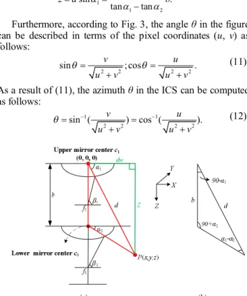
An alternative illustration of the configuration of the upper omni-camera with a hyperboloidal-shaped mirror is shown in Fig. 3, with the WCS specified by (X, Y, Z) and the image coordinate system (ICS) specified by (U, V). The pixel I at image coordinates (u, v) is an image point corresponding to the real-world point P at world coordinates (x, y, z).
Figure 3. System configuration of upper omni-camera with a mirror.
We use two elevation angles of a real-world point P to compute relevant 3D data. The elevation angles can be obtained by using a pano-mapping method proposed by Jeng and Tsai [7]. As shown in Figs. 3 and 4(a), each image point I is the projection of a corresponding real-world point P whose light ray goes onto the mirror of the omni-camera and then is reflected onto the camera imaging plane, resulting in an azimuth angle (shown in Fig. 3) and an elevation angle (shown in Fig. 4(a) as 1 or 2). By the pano-mapping table proposed in Tsai and Jeng [7], if the image coordinates (u, v) of the projection, which is an image point I, of a real-world point P are known, then the elevation angle and the azimuth angle can be obtained by table lookup using the pano-mapping table. Also, according to the mirror surface geometry, a relationship, called the radial stretching function and denoted as r = f(), between the elevation angle and the radial distance r of I in the image plane with respect to the image center has been established. The details of the process are omitted here due to the page limit. Since two cameras are used in each imaging device, there are two of such angles, which we denote as α1 and α2, as shown in Fig. 4(a). Also, we assume that the upper mirror center is the WCS origin (0, 0, 0).
The goal of 3D data acquisition now is to use α1 and α2 to compute (x, y, z).
For this, as shown in Fig. 4(b), by the triangulation principle, the distance d between the real-world point P and the center of the upper mirror c1 may be computed as
2 1 2
sin(90 ) sin( ),
d b
(8)
where b is the disparity between the two cameras of the two- camera imaging device which has been measured manually to be b = 24.2 cm. Eq. (8) may be reduced to be:
1 1 2
1 1
cos tan tan ,
d b
(9)
and the horizontal distance dw and the vertical distance z in Fig. 4(a) may thus be computed respectively by:
1 1 2
1 1
1 2
cos 1 ;
tan tan
sin tan .
tan tan
dw d b
z d b
(10)
Furthermore, according to Fig. 3, the angle θ in the figure can be described in terms of the pixel coordinates (u, v) as follows:
2 2 2 2
sin v ; cos u .
u v u v
(11)
As a result of (11), the azimuth θ in the ICS can be computed as follows:
1 1
2 2 2 2
sin ( v ) cos ( u ).
u v u v
(12)
(a) (b)
Figure 4. Computation of depth using a two-camera imaging device. (a) The ray tracing of a real-world point P in an imaging device with two hyperboloidal-shaped mirrors. (b) The red triangle in (a) shown in detail.
According to the characteristic that the axes of the cameras are aligned with the axis of the mirror as well as the rotational symmetry property of the omni-camera, the azimuth angle of point P in the WCS and the azimuth angle of the corresponding point I in the ICS are the same. Denoting both of them by , we can compute the values of x and y in the WCS as:
1 2
1 2
cos cos ;
tan tan
sin sin .
tan tan
x dw b
y dw b
(13)
In summary, given the image pixel of a real-world point P, we can compute its azimuth θ in the image and get a pair of elevation angles α1 and α2 by pano-mapping table lookup.
Then, the unique 3D position of P described by world coordinates (x, y, z) can be found. Therefore, if a pair of matching points (one is in an omni-image taken by the upper omni-camera, and the other is in an omni-image taken by the lower omni-camera) is known, relevant 3D data of the corresponding real-world point P can be computed.
IV. AUTOMATIC DETECTION OF ASUSPICIOUS PASSER-BY WITH A TWO-CAMERA OMNI-DIRECTIONAL IMAGING DEVICE
In this study, we propose a technique to detect a suspicious passer-by near a video surveillance car and estimate his/her location and height for use in various security applications using a two-camera omni-directional imaging device. Also, according to the information of a passer-by’s location, a corresponding perspective view can be computed by a method proposed in Jeng and Tsai [7].
A. Detection of Moving Objects in Omni-images
Before extracting moving objects around a video surveillance car, background images without objects are captured in advance. And to detect moving objects, current foreground images are taken in real-time. An example of background and foreground images is shown in Fig. 5.
(a) (b)
Figure 5. Background images of proposed two-camera imaging device. (a) Background taken by upper camera. (b) Background taken by lower camera.
Then, we transform the color background and foreground images into two grayscale ones. By subtracting the background image from the foreground one, we can obtain all differences between the two images. Because there is a lot of noise in the surveillance area, such as those caused by light variations, we set an appropriate threshold parameter tTH to threshold the difference image to eliminate noise. The value tTH we use in this study is a dynamic threshold value yielded by using moment-preserving thresholding proposed by Tsai [8]. If the difference value of a pixel is larger than tTH, it is recorded as “1”; else, as “0”. After this bi-level thresholding process, we can obtain a binary image IBI with detected moving objects labeled as “1.” A sequence of images yielded as intermediate results of this object detection process is shown in Fig. 6.
B. Detection of a Passer-by’s Head by Compoent Labeling Before introducing the technique we propose to detect a passer-by’s head, with Fig. 7 as an illustration we state a well- known property of omni-image: each line L, which is horizontal to the Z-axis in the WCS, will be projected onto the image as a line IL going through the image center Oc.
If a passer-by around of the video surveillance car stands on the ground, it is means that the axis of his/her body is vertical to the ground. Accordingly, as illustrated in Fig. 8(a), the midline IL of the passer-by (i.e., the axis of his/her body) will definitely go through the center of the omni-image Oc As a result, my may find the top of a passer-by’s head simply by the following steps: (1) scan each line in the radial direction through the image center based on the polar coordinates (θ, r),
where θ is the azimuth angle and r the radial length; (2) find a sufficiently long line segment with at least 15 consecutive pixels; and (3) find the farthest point with respect to the image center as the passer-by’s head location.
The result of passer-by’s head detection in Fig. 6 is shown in Fig. 8(b).
(a) (b)
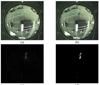
(c) (d)
Figure 6. Passers-by detection. (a) Background image. (b) Image with a pedestrian. (c) Difference image obtained after subtraction of (b) from (a) (d) Binary image obtained by moment-preserving thresholding [8].
Figure 7. A specific property of an omni-camera: projection of a vertical space line will result in a line going through the image center.
(a) (b)
Figure 8. Passer-by head detection (a) Midline of passer-by going through image center. (b) Result of detection of Figure 6(d) (head marked in red.).
C. Computation of Passer-by’s Location and Body Height With a passer-by’s head detected in the images taken by the upper and lower cameras of a two-camera imaging device, the formulas derived in Section III.B may be used to compute the location (x, y) of the passer-by and his/her body height h.
Specifically, the location (x, y) is just that described by Eqs.
(13). And the body height h may be computed as h = hu z where hu is the height of the upper camera with respect to the ground (measured manually to be 256 cm in this study) and z is as computed by Eq. (10) because P is the passer-by’s head top point.
V. GENERATION OF TOP-AND PERSPECTIVE-VIEW IMAGES
A. Construction of a top-view image with an omni-camera Because the FOV of the upper camera in a two-camera imaging device is wider than the lower one, we use the upper camera to construct a top-view image. The height of the camera affixed on the car roof is known in advance. Also, it is assumed that all pixels surrounding the car in the image are projections of real-world points on the ground. Fig. 9 illustrates the geometric relationship between a ground point and the upper camera.
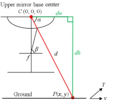
Figure 9. Ray tracing of a scene point P on ground onto mirror.
We then use a “backward mapping” scheme to compute the desired top-view image. First, according to Fig. 9 we may compute the horizontal distance, dw, between a real-world point and the mirror base center in terms of the coordinates (x, y) of a point P in the WCS as follows:
dw x2y2
Accordingly, the azimuth angle θ can be derived as:
cos1 x sin1 y .
dw dw
Alternatively, dw may be computed as dw = dhcot() which leads to
tan 1dh
dw
On the other hand, using the radial stretching function r = f() mentioned previously, the radial distance r corresponding to
can be derived. Accordingly, by the rotational-invariant property of the omni-camera, the image coordinates (u, v) of the corresponding pixel I in the ICS can be obtained from (15) as follows:
urcos ; vrsin .
As a result, a complete top-view image can be computed, as shown in Fig. 10(b).
B. Merging of two top-view images into a single one At the beginning, we construct two top-view images using the omni-images taken from the two upper cameras. It is assumed that the relative position of the two upper cameras may be measured in advance and described by offsets (CW, CL) which are the horizontal and vertical distances between the cameras, respectively, as illustrated in Fig. 11. The offsets are (110, 330) for the car used in our experiments. To make the merging of the two images simple and fast, we divide the desired top-view image around the video surveillance car into two parts. One part is taken from the front half top-view of the car surrounding area (covering the image’s upper part before the spot at CL2) taken by the front upper camera, and the other is the rear half top-view of the car surrounding area (covering the image’s lower part behind the spot at CL2) taken by the rear upper camera. All the pixels in the latter part are shifted for an offset of the previously-mentioned amounts before being merged to the former part. Thus, an example of a preliminarily top-view image so integrated is shown in Fig.
11(a). To obtain further a good-looking top-view image, an eclipse shape is used as the viewing window. The pixels outside the eclipse shape are discarded. In this way, a final integrated top-view image of that of Fig. 11(a) can be obtained, as shown in Fig. 11(b).
(a) (b)
Figure 10. An omni-image and its corresponding top-view images. (a) An omni-image. (b) A top-view image obtained from backward mapping.
(a) (b)
Figure 11. Top-view image construction. (a) A preliminarily integrated top- view image. (b) An integrated top-view image enclosed by an eclipse shape.
C. Video Surveillance Car Shape Superimposition
Because the two imaging devices are affixed on the car roof, the car shape in the top-view image is always fixed.
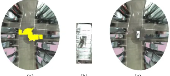
Therefore, we can superimpose a real car shape on a top-view image in the learning process. For this, a real car shape is selected manually in advance. Next, as shown in Fig. 12(a), the car shape appearing each non-integrated omni-image taken by either upper camera is marked in yellow. A simple texture
CW
CL
Cm of front camera
Cm of rear camera
synthesis scheme is then adopted to fill ground texture into the car shape area in the following way: for each car shape pixel Ic, find the closest non-car shape pixel In to Ic, and use the color of In to fill Ic. Furthermore, the corresponding relations of all pixels within the car shape with those outside the car shape is stored into a table for use in the later real-time top-view image generation process to improve the program speed. After filling the ground texture, a top-view image portion of a real car shape as shown in Fig. 12(b) is superimposed on the corresponding position in the integrated top-view image, resulting in a better-looking image as shown in Fig. 12(c).
(a) (b) (c)
Figure 12. Filling real car shape into top-view image. (a) An integrated top- view image with car shape marked in yellow. (b) A real car shape. (c) Result of ground texture filling and real car shape superimposition.
D. Generation of Perspective-view Images
The construction of a perspective-view image from an omni-image is carried out in this study through the aid of a pano-mapping table [7]. Given an input omni-image R, the idea is: (1) map each image pixel p in the desired perspective- image Q at coordinates (k, l) to a pair of elevation and azimuth angles (, ) in the pano-mapping table according to the geometry of perspective transformation; (2) find the content (u, v) at the table entry of (, ); and (3) assign the color value of the pixel at coordinates (u, v) of R to pixel p in Q. The detail of mapping (k, l) to (, ) is omitted here due to the page limit.
An example of the experimental results is shown in Fig. 13.
VI. EXPERIMENTAL RESULTS
The experimental environment is an open space area. The tested system functions included construction of an integrated top-view image, generation of a perspective-view image whose view direction may be specified, and detection of a passer-by around the car. More specifically, the imaging devices, after being affixed, were used to compute relevant 3D data of objects. Then, an integrated top-view image was obtained to show the surrounding environment of the car from the top. Also, any passer-by was detected automatically and marked on the top-view image. A corresponding perspective- view image was generated for inspection. Two real examples of the experimental results are shown in Fig. 14.
VII. CONCLUSSIONS
In this paper, a pair of new two-camera omni-directional imaging devices has been designed and affixed on a video surveillance car to develop a video surveillance system for monitoring car neighborhoods. A passer-by around can be detected automatically, with his/her location and body height
being computed. And the corresponding perspective view image and a top-view image can be also generated in accordance for real-time inspection. The system is convenient for real applications. The experimental results show the feasibility of the proposed method.
REFERENCES
[1] Y. Onoe, N. Yokoya, K Yamazawa, and H. Takemura, “Visual Surveillance and Monitoring System Using an Omnidirectional Video Camera,” Proc. 1998 Int’l Conf. Pattern Recog., Vol. 1, pp.588-592, Brisbane, Australia, Aug. 16-20, 1998.
[2] T. Mituyosi, Y. Yagi, and M. Yachida, “Real-time Human Feature Acquisition and Human Tracking by Omnidirectional mage Sensor,”
Proc. IEEE Int’l Conf. Multisensor Fusion & Integration for Intelligent Systems, pp. 258-263, Tokyo, Japan, July 30-Aug. 1, 2003.
[3] S. Morita, K. Yamazawa, and N. Yokoya, “Networked Video Surveillance Using Multiple Omnidirectional Cameras,” Proc. 2003 IEEE Int’l Symp. Computational Intelligence in Robotics & Automation, Vol. 3, pp.1245-1250, Kobe, Japan, July 16-20, 2003.
[4] H. Koyasu, J. Miura and Y. Shirai, “Real-time Omnidirectional Stereo for Obstacle Detection and Tracking in Dynamic Environments,” Proc.
2001 IEEE/RSJ Int’l Conf. Intelligent Robots & Systems, Vol. 1, pp. 31- 36, Maui, Hawaii, USA, Oct. - Nov., 2001.
[5] H. Ukida, N. Yamato, Y Tanimoto, T Sano, and H. Yamamoto, “Omni- directional 3D Measurement by Hyperbolic Mirror Cameras and Pattern Projection,” Proc. 2008 IEEE Conf. Instrumentation &
Measurement Technology, pp. 365-370, Victoria, BC, Canada, 2008.
[6] J. I. Meguro, J, I, Takiguchi, and Y, A, T, Hashizume, “3D Reconstruction Using Multi-baseline Omni-directional Motion Stereo Based on GPS/DR Compound Navigation System,” Int’l J. of Robotics Research, Vol. 26, No. 6, pp.625-636, June 2007.
[7] S. W. Jeng and W. H. Tsai, “Using Pano-mapping Tables for Unwarping of Omni-images into Panoramic and Perspective-view Images,” J. of IET Image Proc., Vol. 1, No. 2, pp. 149-155, June 2007.
[8] W. H. Tsai, “Moment-preserving Thresholding: A New Approach,”
Computer Vision, Graphics, & Image Proc., Vol. 29, No. 3, pp. 377- 393, 1985.
(a) (b)
Figure 13. Generated perspective-view image. (a) Original omni-image. (b) A generated perspective-view iimage.
(a) (b)
Figure 14. Examples of images generated by proposed system in which the right lower corner shows a generated perspective-view image corresponding to the view dierection specified by the red spot (the location of the passer-by) in the main image. (a) Example 1. (b) Example 2.
θ