The Development of an Artificial Neural
Networks Aided Image Localization Scheme for
Indoor Navigation Applications with Floor Plans
Built by Multi-platform Mobile Mapping Systems
Jhen-Kai Liao, Guang-Je Tsai, National Cheng Kung University, Taiwan
BIOGRAPHY
Jhen-Kai Liao is a Ph.D. candidate at the Department of Geomatics, National Cheng Kung University, Taiwan. He is a member of Positioning, Orientation and Integrated Navigation Technologies Lab under the supervision of Dr. Kai-Wei Chiang and Dr. Hsiu-Wen Chang. He is working on sensor calibration, mobile mapping, and indoor navigation.
Guang-Je Tsai is a Ph.D. candidate at the Department of Geomatics, National Cheng Kung University, Taiwan. He is a member of Positioning, Orientation and Integrated Navigation Technologies Lab under the supervision of Dr. Kai-Wei Chiang. He is interested in the simultaneous localization and mapping, integrated navigation system and mobile mapping.
ABSTRACT
Indoor navigation and mapping is popular because of the indispensable smartphone in our daily life. Among all the indoor navigation techniques Pedestrian Dead Reckoning (PDR) has the most potential to confront the challenges of a GNSS-denied environment based on the various embedded sensors. However, PDR has inherent time accumulated errors and aided algorithms such as external infrastructure, frequently stable update and map information, are needed to maintain acceptable result. Another option is to use the image-based localization which detects georeferenced markers in the image to estimate the camera’s position. For this technique, the automation and fast implementation become important. The proposed indoor navigation system is based on the embedded sensors and the integration of two technologies: Artificial Neural Networks (ANN) aided image-based localization and PDR. The distributed georeferenced markers and floor plan are produced by joint Mobile Mapping Systems (MMSs) first. Then, ANN is novel applied to estimate the distance between the marker and camera in real-time. Finally, the camera position is updated through the detected georeferenced marker, estimated distance and orientation from inertial sensor on real time in order to maintain the stable indoor positioning. Compare to the traditional marker-based localization and PDR, the proposed ANN aided image-based localization has better performance, less computational burden and more effective range of marker detection. Meanwhile, the proposed integrated system mitigates the challenges of PDR and image-based localization when they are used independently. The result shows the proposed system is able to initialize in indoor without manually given initial position and provides long-term accurate indoor localization without any infrastructures. In addition, the use of the joint operation of different MMSs for the necessary information collection is flexible, low labor and fast implementation. Especially, the accurate floor plan is the cornerstone of the indoor navigation whether it is for map aided algorithm or presentation.
1 INTRODUCTION
Mobile mapping system (MMS) plays an important role in modern survey and mapping applications since the integration of inertial navigation system (INS) and Global Navigation Satellite System (GNSS) has become mature. With photogrammetry technology, MMS significantly improves the time-consuming procedure of traditional survey. One of the fundamental concepts of MMS was originally evolved from aerial photogrammetry called georeferencing [1]. Georeferencing means the coordinate system of a map or aerial image can be related to a ground coordinate system. Therefore, the ground coordinate of an interesting point in an image can be directly measured, and the spatial information can be further extracted. The forerunner of land-based MMS was originally developed for highway infrastructure mapping and transportation corridor inventories [2]. With the evolution of this technology, the prototypes of land-based MMS have been firstly developed with the clearer definition in the United States and Canada [3, 4]. Meanwhile, more and more MMSs sprung up during this period, and have been applied on airborne and land vehicle with different sensors and algorithms such as digital camera, LIDAR, Differential Global Positioning System (DGPS) and INS [5-8]. Since the INS/GPS integration became mature, MMS can georeference the image without any ground control points. Tao and Li summarized the developments of MMS during this period [9]. Nowadays, because the quality of sensors and the performance of algorithms progress significantly, the application and platform can be
more flexible. The portable and unmanned aerial vehicle (UAV) MMSs has been applied to indoor mapping [10-13]. Therefore, using MMS to obtain the spatial information for indoor navigation application has become possible.
However, when the MMS used in a GNSS-denied environment, there is not only the mapping problem but also the localization requirement. Simultaneous localization and mapping (SLAM) problem is generally solved by the technologies such as robotic visons with the camera, LIDAR or RGB-D sensor [14, 15]. Because most of robotic navigations are based on building maps, therefore generating a relatively reliable floor plan has become important [16]. Similarly, the indoor map or floor plan are also important for indoor pedestrian navigation because of the absolute scale. From the viewpoint of used method, the maps produced by two-dimensional (2D) SLAM can be classified as a landmark-based map [17] and occupancy grid map [18]. Therefore, there is another solution for indoor mapping except the INS/GNSS-based MMS. The environmental challenges can be overcome through the joint operation of abovementioned technologies. Meanwhile, the necessary information for the indoor navigation system can be entirely collected. This research proposes an indoor mapping procedure based on two kinds of MMSs: the portable (camera-based) and UAV (LIDAR-based) MMS for efficient generation of georeferenced image and indoor floor plan, respectively. If the LIDAR used on portable MMS, it may scan a lots of obstacles because the lower height of the portable MMS. On the other hand, if the required devices of georeferencing used on UAV, the load is too heavy. In addition, this research also proposes a procedure for smoothed and rectified floor plan which has accurate scale and global coordinate. Indoor navigation technology has many kinds of the method which based on different principles and equipment, and has been developed over two decades [19]. Some of the methods depend on the intensive or advanced infrastructures to achieve high accuracy. For this group of methods, the user may require a specific device to transmit or receive the corresponding signal. Similarly, the accurate inertial-based methods usually equip the multi-sensors on the specific parts of user’s body [20]. Those requirements also increase cost and inconvenient for people to use indoor navigation services. The appearance of smartphone encourages the new technological revolution of indoor navigation. The various sensors have been embedded in a smartphone such as an accelerometer, gyro, magnetometer and camera. Liu et al. propose a smartphone-based indoor positioning system which only uses the built-in hardware and computational resources [21]. In addition to various sensors, the high popularity is another reason that makes smartphone became an ideal mobile navigator. In recent years, the user has been accustomed to using a smartphone for outdoor navigation based on GNSS. However, people actually spend their daily activities about 90% in indoor which is a GNSS-denied environment [22]. Fortunately, the characteristic of various sensors embedded in the smartphone enables advanced navigation technology by utilizing sensors’ complementarity. One of the most famous mobile game in 2016 called Pokemon GO has promote the augmented reality (AR) application on a smartphone. Many experts have already reported the impacts of this phenomenon on Location Based Services (LBS). AR connects the real world and virtual information by camera. Therefore, if the user is accustomed to using the smartphone camera for LBS, an indoor image-based localization can be considered as the ideal positioning system.
The image-based localization can be used for indoor navigation since the smartphone continuous to have an enhanced camera. The mainstream of image-based localization can be found in robotic vision such as abovementioned SLAM and visual odometry [23]. However, the successive stereo pairs or multi cameras are needed for such methods which are inconvenient for smartphone-based navigation. In addition, some image-based localizations use a query image to match the reference images in a database in order to find the user’s location [24]. However, the challenges of feature recognition and image matching are unavoidable. Therefore, the integration of other positioning systems has been considered to improve the accuracy and time-consuming procedure of image processing [25]. Another method for reducing the burden of image processing is using the marker which can be located at some interesting points [26]. Mulloni et al. implemented the image-based localization based on the camera phone and fiduciary marker, and received the good feedbacks from users [27]. However, most of the image-based localizations are in a relative coordinate system, even using the locating marker. In order to navigate in the ground (global) coordinate system, the use of the georeferenced image is required. Space resection is a photogrammetric method that used to determine the ground 3D position and attitude of a camera by single georeferenced image [1]. However, since the collinearity equations are nonlinear, and should be linearized using Taylor’s theorem, initial values are needed for the iterative calculation. Li et al. propose a hybrid image-based localization for seamless navigation based on GNSS, compass, calibrated camera and space resection with georeferenced images [28]. They mentioned the challenge of the initial value of space resection for the indoor case. In summary, technique based image-based localization for indoor pedestrian navigation using a smartphone has the following issues: the requirement of multiple cameras, the computational burden of image processing, limitation of relative coordinate system and initial value problem. Therefore, this research uses a self-designed marker to reduce the burden of image processing. Each marker is georeferenced with the ground coordinate system by joint operation of MMS. Meanwhile, this research proposes the novel use of the Artificial Neural Network (ANN) to estimate the accurate distance between camera and marker, and further used to positioning. The effective distance can achieve ten meters between the camera and marker which is usually challenging for traditional marker-based localization. Finally, abovementioned inconvenient can be avoided.
ANN is designed to behave like the human intelligence by utilizing adaptive models that can learn from the existing data and then generalize what has been learned [29]. This technology has been early verified as an effective tool for providing solutions to certain engineering and science problems that cannot be solved properly using conventional techniques [30]. The model of
ANN is based on empirical learning thus it does not require certain statistical assumption or detail knowledge. The networks of ANN are composed of a number of nonlinear computation elements. Those elements are operated in parallel and are arranged in a way like biological neural interconnections. Using ANN to assist the navigation is has a long history especially for robotic and land vehicle navigation [31, 32]. For indoor navigation, ANN usually is applied for the technologies based on received signal strength indicator (RSSI), such as Wi-Fi [33], Bluetooth [34] and radio-frequency identification (RFID) [35]. Some researches use ANN or artificial intelligence algorithm for motion recognition and step length estimation based on inertial sensors [36, 37]. For indoor image localization, ANN is often used for image recognition and classification to distinguish the navigable area or specific marker [38, 39]. This research proposes a novel use of ANN to estimate the distance between the self-designed marker and camera. The distance can be as far as ten meters that depend on the camera resolution. Then, the position of the camera can be accurately estimated after the first marker recognition by using the single georeferenced image and orientation sensor. By this implementation, the proposed system is positioned in the ground coordinate system without initial value problem and heavy burden of image processing, meanwhile only single camera is required. However, pure image-based localization still needs to integrate with other positioning technology for continuous navigation in terms of no detection of georeferenced markers.
Pedestrian Dead Reckoning (PDR) is one of the most common used technologies for smartphone-based pedestrian indoor navigation. The concept of PDR is to estimate the two-dimensional location of pedestrian based on travelled distance and heading derived from the accelerometer, gyro and magnetometer. However, the possibly missed step, inaccurate step length and heading error produce the accumulated position error [40, 41]. Most of the accurate estimations of step and corresponding step length need the pre-calibration or post-processing [42]. However, those systems depend on tuning parameters usually has the risk that the demonstration system performs better than the commercial production [43]. For heading estimation, magnetometer and gyro are generally used. However, some environments retain lots of magnetic materials and devices are suffered from strong disturbing magnetic field. Therefore, the magnetic heading is possible to lose accuracy in a magnetic-hostile environment. Gyro is an environment-independent sensor which estimates the heading by adding angular change on initial heading. It is obvious that it requires an initial heading, and the error will accumulate with time. Consequently, magnetometer and gyro are complementary for better heading estimation, but even with the integrated heading, the performance heavily depends on the tuned parameters of integration algorithm which related to the environmental magnetic field as well as the specifications of gyro sensors. One more issue of PDR is that it requires initialization to have its own relative positioning system.
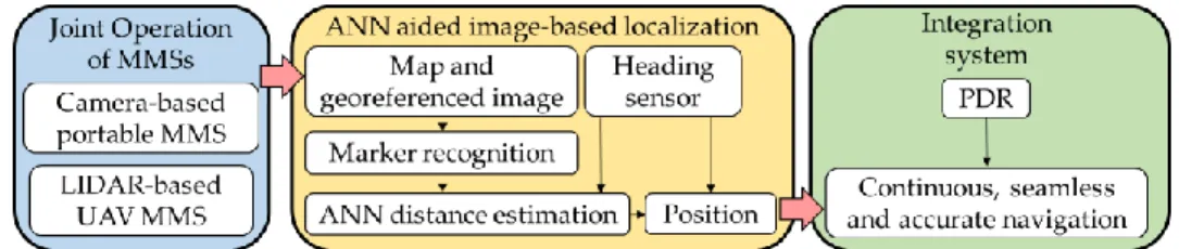
A short summary, this research first proposes a procedure of joint operation of two kinds of MMS to overcome the environmental challenges: the portable (camera-based) and UAV (LIDAR-based) MMS for georeferenced image and indoor floor plan, respectively. Because the lower height of portable MMS and limited load of UAV MMS, the joint operation is necessary. In addition, a procedure of the generation of smoothed and rectified floor plan is proposed since the accurate floor plan with absolute scale is important for indoor navigation, such as demonstrating navigation result and map matching. The inaccurate floor plan will make the accurate positioning solution looked worse. Meanwhile, the floor plan with global coordinate system is important for seamless navigation when the outdoor world desired to connect with indoor. After the accurate indoor floor plan and georeferenced image are obtained, a novel ANN aided image-based localization to integrated to PDR for smartphone-based indoor navigation is proposed to run in real-time. The purpose of ANN is to estimate the accurate distance between the camera and the self-designed marker. Then the position of the camera can be estimated with georeferenced image and orientation sensor. The integration of two positioning algorithms can provide the continuous navigation without successively taking images as well as reducing the accumulated PDR error. In addition, the proposed long-term positioning system only requires one smartphone for accurate indoor navigation that also has the advantages of seamless navigation, less burden of image processing and ability of initialization without any infrastructures. To demonstrate the performance, this research compares three kinds of position estimation based on the marker recognition. The outline of this research is shown in Figure 1.
Figure 1. The primary contribution of this research
2 METHODOLOGY
This section will include three subsections to describe the following methods: joint operation of MMSs, image-based localization and PDR. Finally, the proposed indoor navigation system can be effective created.
2.1 Joint Operation of Multi-platform MMSs
The used MMSs in this research include two kinds of system: portable (camera-based) and UAV (LIDAR-based) MMSs. They are parts of an ongoing developed project at National Cheng Kung University (NCKU). The following sections will explain their system design, the mapping procedure and how the MMSs work.
2.1.1 Portable camera-based MMS
The portable MMS uses an electric cart to carry a dual-frequency GNSS, a navigation grade of INS (iNAV-RQH), a panoramic camera (Ladybug5), an industrial computer and power supply. The specifications of iNAV-RQH and Ladybug5 are shown in Table 1. The MMS and two major sensors are shown in Figure 2.
Table 1. The specifications of iNAV-RQH and Ladybug5
Figure 2. Portable mobile mapping system
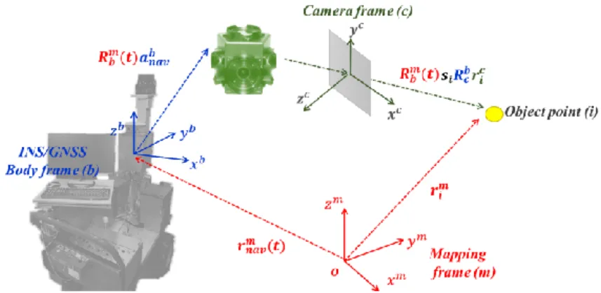
The concept of direct georeferencing is illustrated in Figure 3. Briefly, direct georeferencing means the ground coordinate of an interesting point in an image can be directly measured. This procedure related to a series of coordinate transforms and coordinate vector calculations. The georeferencing formula can be written as:
𝑟𝑖𝑚= 𝑟𝑛𝑎𝑣𝑚 (𝑡) + 𝑅𝑏𝑚(𝑡) × (𝑠𝑖𝑅𝑐𝑏𝑟𝑖𝑐+ 𝑎𝑛𝑎𝑣𝑏 ) (1) where 𝑟𝑖𝑚 is the coordinate vector of i-th interesting point in the mapping frame (m-frame); 𝑟𝑛𝑎𝑣𝑚 (𝑡) is the interpolated coordinate vector at time 𝑡 of the INS/GNSS in the m-frame; 𝑅𝑏𝑚(𝑡) is the interpolated rotation matrix between the navigation system body frame (b-frame) and the m-frame; 𝑠𝑖 is a scale factor determined by stereo techniques; 𝑅𝑐𝑏 is the differential rotation matrix between the camera frame (c-frame) and the b-frame, determined by calibration; 𝑟𝑖𝑐 is the coordinate vector of i-th interesting point in the c-frame (image coordinate); 𝑎𝑛𝑎𝑣𝑏 is the vector between INS/GNSS center and camera principle point, determined by calibration. More detail can be found in [44].
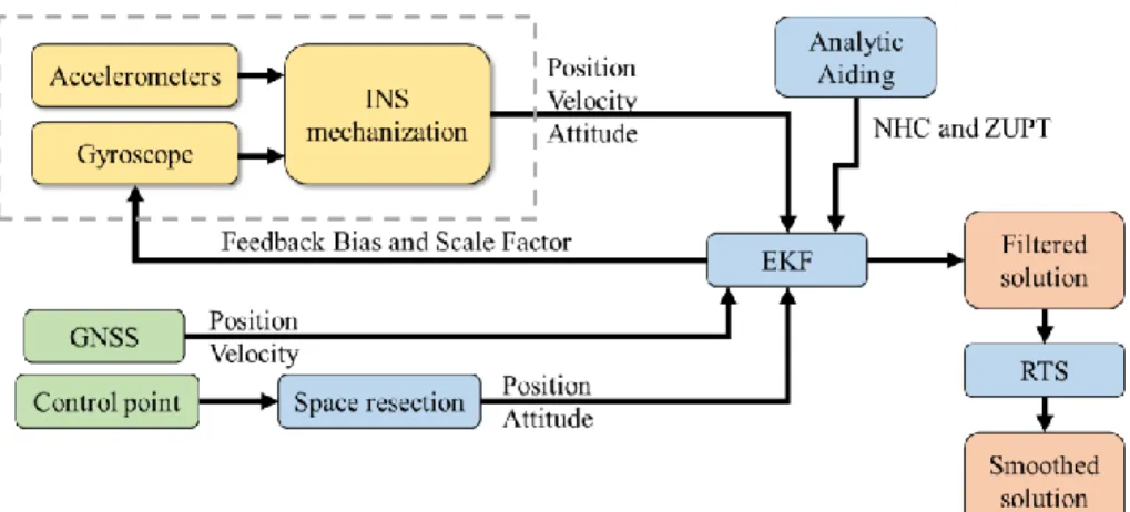
According to this formula, the performance of direct georeferencing is depended on the accuracies of platform’s position and orientation. Therefore, the trajectory of MMS was precisely estimated based on a loosely coupled INS/GNSS integration including Extend Kalman Filter (EKF), Rauch-Tung-Striebel (RTS) smoother, Non-Holonomic Constraint (NHC) and Zero Velocity Update (ZUPT). The architecture of the loosely coupled INS/GNSS integration scheme applied is shown in Figure 4. The formulas of EKF are briefly shown as following:
Component of state vector:
𝑥 = [δ𝑟1×3 δ𝑣1×3 δ∅1×3 𝑏1×3𝑎𝑐𝑐 𝑏
1×3𝑔𝑦𝑟𝑜 𝑠1×3𝑎𝑐𝑐 𝑠1×3𝑔𝑦𝑟𝑜] (2) where x is the state vector; δ𝑟1×3, δ𝑣1×3 and δ∅1×3 are the position, velocity and attitude errors, respectively; 𝑏1×3𝑎𝑐𝑐 and 𝑏1×3𝑔𝑦𝑟𝑜 are the biases of accelerometer and gyro; 𝑠1×3𝑎𝑐𝑐 and 𝑠
1×3𝑔𝑦𝑟𝑜 are the scale factor errors of accelerometer and gyro, respectively.
State vector and measurement:
xk=Φk-1;kxk-1+wk, wk~ N(0, Qk) (3)
zk=Hkxk+𝑣k,𝑣k~ N(0, Rk) (4)
where xk is the state vector at time k; Φk-1;k is the state transition matrix from epoch k-1 to k; wk is the system noise; zk is the updated measurement; Hk is the measurement mapping matrix; 𝑣k is measurement noise.
Predict stage: 𝑥̂k|k-1=Φk-1;k𝑥̂k-1 (5) Pk|k-1=Φk-1;kPk-1Φk-1;kT +Q k (6) Update stage: Kk=Pk|k-1𝐻𝐾𝑇[𝐻𝑘Pk|k-1𝐻𝐾𝑇+Rk]-1 (7) x ̂k=𝑥̂k|k-1+K𝑘[zk-𝐻𝑘𝑥̂k|k-1] (8) 𝑃𝑘=Pk|k-1−K𝑘Hk𝑃𝑘|𝑘−1 (9)
where 𝑥̂k|k-1, Pk|k-1 are the predicted states and covariance at time k, given information at time k-1; 𝑥̂k-1,Pk-1 are the estimated states and covariance at time k-1; x̂k, 𝑃𝑘 are the estimated states and covariance at time k. After EKF estimation, the RTS smoother is applied. Briefly, RTS combines the forward and backward solutions of EKF to provide the optimal estimations of state vector. The formulas of RTS smoother are briefly shown as following:
𝑥̂k:N=𝑥̂k+Ck[𝑥̂𝑘+1|𝑁−Φk;k+1𝑥̂k] (10)
𝑃𝑘|𝑁=𝑃𝑘+Ck[𝑃𝑘+1|𝑁− 𝑃𝑘+1]𝐶𝑘𝑇 (11) 𝐶𝑘=𝑃𝑘Φk;k+1T Pk+1−1 (12)
where 𝑥̂k:N, 𝑃𝑘|𝑁are the smoothed states and covariance at time k, given information up to N (k≤N); 𝐶𝑘 is the cross
covariance. Moreover, the fact that the velocities of y-axis and z-axis of the cart should be zero when the cart is moving along, is applied to restrict the error in horizontal velocities. These constraints, NHC, can be written as following:
zk=[𝑣̂𝑦𝑏− 0; 𝑣̂𝑧𝑏− 0] (13) where 𝑣̂𝑦𝑏 and 𝑣̂𝑧𝑏 are the estimated velocities of y-axis and z-axis in b-frame. Similarly, the velocities of three axes of the cart should be zero when the cart is stopped. The constraint of ZUPT can be written as following:
zk=[𝑣̂𝑁− 0; 𝑣̂𝐸− 0; 𝑣̂𝐷− 0] (14) where 𝑣̂𝑁, 𝑣̂𝐸 and 𝑣̂𝐷 are the estimated velocities in north, east and height directions.
Figure 4. The scheme of loosely INS/GNSS integration
2.1.2 Unmanned aerial vehicle LIDAR-based MMS
The UAV MMS uses LIDAR technology and computes its map thanks to a (LIDAR-based) SLAM approach. The UAV MMS is shown in Figure 5(a). SLAM is an approach that uses relative measurements between the mobile platform and the environment in order to compute both a map (i.e. one representation of the environment) and the pose of the platform. In order to avoid the obstacle scanned by LIDAR, the platform of UAV is needed since the lower height of portable MMS. However, the high grade INS/GNSS system is impossible for UAV because of the limited load. Therefore, the SLAM problem should be solved. It is also known as the global localization problem, where a robot is placed in an unknown environment and has to localize itself from scratch. This research uses the algorithm called occupancy grid map which is a grid-based SLAM algorithm to generate the higher accurate floor plan.
The estimated pose information is an important parameter for scan-matching, as it improves performance. Scan-matching plays a significant role in enhancing navigation results, which gives posterior information to update the filter. Based on the high accuracy of laser scanners (the specification of LIDAR UST-20LX is shown in Table 2), with low distance measurement noise and high scanning rates, scan-matching registers each piece of scanned data and aligning it together or existing map. This LIDAR-based SLAM also has the optimization to align the endpoint of the scan data on the existing map. The idea follows the Gauss-Newton approach [24]. However, since the lack of absolute control, the solution of SLAM will drift with time. Therefore, this research proposes a smoothing procedure for accurate floor plan based on the smoothed navigation information and a RTS smoother (as shown in 2.1.1). The flow chart of the smoothed grid-based SLAM process proposed in this study is shown in Figure 5(b).
Figure 5. The UAV MMS (a) and flowchart of smoothed grid-based SLAM (b) Table 2. The specification of used LIDAR
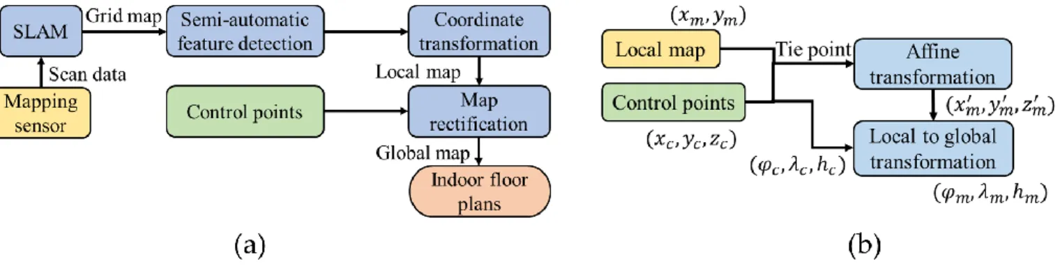
SLAM problem has been studied for many years. Most algorithms achieve robust performance in terms of mapping and localization. The generated map is often used to navigate the robot and implement autonomous motion planning. This research considers the scenario when a user wants to update the map or implement motion planning with a known map, which requires extra effort for initializing the position and orientation. The primary issue is that the map is often generated in different reference frames. For this research, the proposed navigation system is in a global frame since the use of georeferenced image. Another problem is that without any landmarks or aiding information, the accuracy of robot mapping degrades with time. Therefore, this research proposes a map rectification process to rectify and transform the raw map into the global frame with reliable scale and accuracy. The floor plan generalization process is shown in Figure 6(a), and the flow chart of map rectification is shown in Figure 6(b). The local map and control points are first given in the same coordinate system. Map rectification uses the affine transformation [1], which includes six parameters (two translations, two scales, rotation, and shearing). In this transformation, at least three tie points should be selected to calculate the six parameters and eliminate the deformation problem. Therefore, tie point selection greatly affects the accuracy of the rectified map. Tie points should be widely and uniformly placed in distorted areas to control deformation. Finally, the rectified map (𝑥𝑚′ , 𝑦𝑚′, 𝑧𝑚′ ) is transformed into global coordinates (𝜑𝑚, 𝜆𝑚, ℎ𝑚) using the local-to-global transformation. Through the proposed procedure, the accurate floor plan can be used to perfectly demonstrate the navigation solution or further applied the map matching algorithm. Meanwhile, the generating floor plan has the ability to connect the outdoor world for seamless navigation.
Figure 6. The flowchart of floor plan generalization (a) and map rectification (b)
2.1.3 Mapping Procedure
The experimental field is an indoor space with the size 500 meters x 30 meters. The mapping route is around rectangle (the circumference is about 1000 meters) because there are some obstacles in the middle. There is no window because it is underground. Therefore, this GNSS-denied environment is a harsh space for INS/GNSS integration system, even using EKF, smoothing, NHC and ZUPT. Considering the specification of used INS and experimental experience, some first-level control points are required every 200 meters to maintain the accuracy of portable MMS trajectory. At first, the ground coordinates of those first-level control points are surveyed by total station. Then the control points are measured in an image for space resection to estimate the position and attitude of MMS. Then the information is used for update in EKF at that epoch, as shown in Figure 4. The portable MMS was initialized in outdoor, and moved in two small circles to make the EKF stable. Then, the MMS goes into the experimental field, and the trajectory of MMS can be accurately estimated for georeferencing. The produced georeferenced images are further used for UAV MMS and proposed image-based localization.
The georeferenced images are used to generate the more intensive control points called second-level control point for UAV MMS. They are used to correct the floor plan as shown in Figure 6(a). Then, the accurate floor plan is used for indoor navigation. The reason of using UAV MMS for floor plan is that the mapping height can avoid the most of the obstacles such as cars. The flowchart of the joint operation of MMSs in this research is shown in Figure 7. With the help of the joint operation of MMSs, all the required information for the proposed indoor navigation system can be obtained efficiently in a short time.
2.2 Image-based Localization
In order to compare and show the superior performance of the proposed system, three types of image-based localization that based on marker recognition are introduced: localization based on marker distortion, ANN aiding and space resection. The comparison will show in the section of results, and then the best method is applied in the proposed indoor navigation system to show performance in terms of the trajectory.
2.2.1 Novel marker and recognition
This study designs and implements a marker used to reduce the burden of image processing such as in terms of photogrammetry process and feature recognition. It is based on the data matrix code which includes the information of marker ID, building ID, floor, orientation, etc. Because all the markers are georeferenced, the position and orientation of each marker are retrieved from the database once finished the marker recognition. In addition, the design of two rectangles provide the georeferenced vertexes for space resection. The designed marker is shown in Figure 8(b). The recognition procedure has the following processes: RGB to greyscale, binarization, edge extraction and dilation, as shown in Figure 8(a). The equation of change an RGB image to grayscale image is shown in the following equation:
𝑙 = 0.2989 × 𝑅 + 0.5870 × 𝐺 + 0.1140 × 𝐵 (15) where l is the grayscale value; R, G, and B are the red, green and blue color values from 0 to 255, respectively. The binarization is based on the fixed threshold method. The edge extraction is based on the well-known Sobel operator:
𝐺𝑥 = [−1 0 1−2 0 2 −1 0 1] ∗ 𝐽, 𝐺𝑦= [ −1 −2 −1 0 0 0 1 2 1 ] ∗ 𝐽 (16) 𝐺 = √𝐺𝑥2+ 𝐺𝑦2 (17) where J is the raw image; 𝐺𝑥 and 𝐺𝑦 are two images after horizontal and vertical edge detection; * is the two-dimensional convolution operation; G is the gradient magnitude. The edge is decided by the comparison between G and the threshold. The dilation is the process based on the morphology which fills up the closed areas. The recognition procedure further finds out the maximum area for further vertex detection. The concept is using the slash with 45 degrees to find the first encountered white point, as shown in Figure 8(c). Once the four vertexes are found, the affine transformation can be implemented. Then the detected marker can be adjusted to the original shape with a certain size for decoding the data matrix. If the decoding failed, the procedure goes back to find the next maximum area for decoding. The data matrix is in binary format. Then, the position and heading (frontal direction) of recognized marker can be obtained for further localization.
Figure 8. The procedure of marker recognition (a), self-designed marker (b) and concept of vertex detection (c)
The marker distribution is depending on the number of interesting point (entrance, elevator, toilet, etc.) and camera resolution. Since the data matrix should be clear enough for decoding, the effective range of our marker is a circle with ten meters’ radius. If the user wants to initialize itself everywhere without any further infrastructures such as BLE, the better interval between each marker is twenty meters based on this design. It is worth mentioning that the integration of PDR can extend this interval depend on the performance of PDR model. But since the step length can vary as much as 50% regarding different walking speeds and individuals, PDR will produce the error about five meters after ten meters travelled in the worst case. Therefore, if the proposed navigation system desired to reach the accuracy of five meters, the maximum interval between each marker can
extend to thirty meters. The future work of this research will also consider how to extend the effective distance of marker recognition by ANN.
2.2.2 Localization based on marker distortion
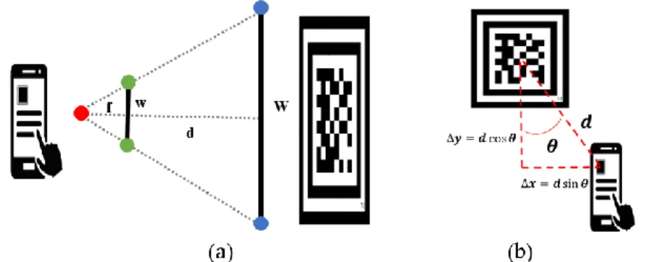
Localization based on marker distortion is a simple method. When the principle distance (which is also called focal length on certain conditions), image pixel size, detected marker size and real marker size are known, the distance between the camera and the recognized marker can be easily estimated through the following equation:
𝑑 =𝑤𝑓 × 𝑊 (18) where d is the distance between the camera and marker; f is the principle distance; w is the detected side length of the marker in pixels; W is real side length of the marker in meters. The concept of distance estimation is shown in Figure 9(a). It’s worth to mention that the used principle distance in this research is recorded in the image file which is inaccurate. The Equation (18) is applied for the longest side of detected marker. The position of camera is then estimated by this distance and angle (θ) (between the headings of camera and marker). The concept of position estimation is shown in Figure 9(b). However, if the image is not taking at the perpendicular direction of the marker with large angle (θ), and the inaccurate principle distance is used, the distance and position estimations are inaccurate through this method. Therefore, this research further proposes the ANN aided image-based localization in improving the distance and position estimations after marker recogniton.
Figure 9. The concept of distance estimation based on marker distortion (a) and further estimated the position (b)
2.2.3 Artificial neural network aided localization
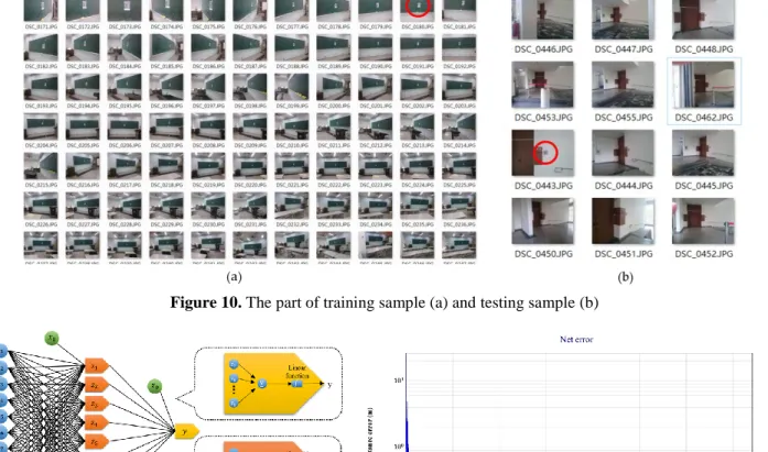
In order to obtain the accurate distance estimation, this research proposes an ANN aided method. Unlike the most of traditional ANN used in image processing, this research uses ANN to estimate the accurate distance between the camera and the marker, especially when the image is taken from the larger angle θ and longer distance. The Multi-Layer Perceptron (MLP) is applied in this study. MLP has been applied successfully to solve some difficult and diverse problems by supervised learning with an error back-propagation algorithm. MLP can be viewed as a logistic regression classifier, which consists of the input layer, output layer, and one or more hidden layers. Each node in the output and hidden layers is a neuron with activation function. MLP is a supervised neural network since it requires the target signal to train the network based on the error-correction learning rule, which consists of two passes through the different layers of the network. The first pass is a forward pass with fixed weights that propagates input vector through the neurons, then produces the output. The second pass is a backward pass which the synaptic weights are adjusted using the error signal propagate backward. More details can be found in [45]. The input vector contains the pixel coordinates of four marker vertexes, the area of the recognized marker, the estimated distance from marker distortion and sensor orientation. The output of the network is the distance between the camera and marker. The training sample has 200 images taking from different camera angle (relative to the perpendicular direction of marker) and distance, part of them are shown in Figure 10(a). They are toke at the training filed. The testing sample has 32 images toke at the testing field which are independent to the training sample, part of them are shown in Figure 10(b). In Figure 10, the red circle indicates the position of marker in one of the images. The accuracy analysis is shown in section 3.2. Figure 11(a) is the architecture of used MLP network that includes 11 input neurons (𝑥𝑖), 8 hidden neurons (𝑧𝑖) within one hidden layer and 1 output neuron (y). The used activation functions in MLP are logistic sigmoid function and linear function for hidden and output layer, respectively. Meanwhile, the training algorithm use momentum at 0.2 and learning rate at 0.05. The back-propagation weight update formula can be written as following Eq. (19). The training result is shown in Figure 11(b), where the x-axis is the number of iterations and the y-axis is the root mean square error (RMSE) of distance estimation of testing sample. Once the accurate distance is obtained, the accurate position can be estimated through the method as shown in Figure 9(b).
where ∆w𝑛 is the weight change at iteration n; 𝑔𝑛 is the steepest descent direction of the network error function; 𝜇 is the momentum; δ is the learning rate.
Figure 10. The part of training sample (a) and testing sample (b)
Figure 11. The used architecture of MLP (a) and the training result (b)
2.2.4 Localization by space resection
Space resection is a photogrammetric method that determines the six exterior orientation parameters (EOPs) of the exposure center of a single photograph. The EOPs include the 3D positions (X, Y, Z) and attitude angles (omega, phi and kappa). They are solved by the collinearity equations and a photographic image with the known principal distance of the camera, as well as at least three control points in the image whose 3D ground coordinates are known. The collinearity equations are based on the condition that the camera, the control point (object point) and its corresponding image point all lie on a straight line. The used control points are extracted from the marker in this research, and their 3D ground coordinates are recorded by the georeferenced image. The concept of space resection that used in this research with the self-design marker is shown in Figure 12, and the collinearity equations are shown as following:
Figure 12. The concept of space resection with marker recognition
xa=xp-∆x-c[m11(XA-XL)+m12(YA-YL)+m13(ZA-ZL)
m31(XA-XL)+m32(YA-YL)+m33(ZA-ZL)] (20)
where (XA,YA,ZA) is the ground coordinate of interesting object point A; The matrix m is a 3D rotation matrix that includes the elements composed of three attitude angles: omega, phi and kappa; (XL,YL, ZL) is the ground coordinate of the camera. The three attitude angles and the location of camera are the elements of EOPs; (xa,ya) is the measured image coordinate of object point A; (xp, yp) and c are principle point offsets and principal distance of camera respectively, which compose the interior orientation parameters (IOPs). Furthermore, the generalized IOPs include the additional parameters: ∆x and ∆y, which represents the system error of cameras such as the correction of principle distance and lens distortion. Space resection by collinearity equations is a purely numerical method, and the usage of least squares is usually applied when redundant amounts of control points exist. However, in the least squares method the nonlinear collinearity equations are linearized using Taylor’s series, the initial values of the exterior parameter are needed for the iterative calculation to converge. The initial positions are provided by the previous methods: localization by marker distortion or ANN method after recognized the marker. The initial orientations are provided by orientation sensor. All the IOPs are calibrated for better estimation. The comparison between the above-mentioned methods will be discussed in the result section (such as the improvement after space resection using the initial position from ANN method).
2.3 Integration with Pedestrian Dead Reckoning
PDR is used in the proposed system to increase the solution rate by avoiding the successively taking images. In the scope of PDR, calibrations such as step length, magnetic field and system errors of inertial sensors are required and time consuming. It is obvious that if PDR is well calibrated, the fewer makers for image-based localization are needed to reduce the accumulated error. The main reason to propose a PDR system that integrated with image-based localization is to not only avoid the model calibration but also an effective way to initialize. In this research, all the used coefficients of PDR are fixed regardless the users and smartphones. This design is used to prove the proposed system is flexible and easy to use. The proposed PDR uses the ANN aided image-based localization as the external position update. The integrated architecture is shown in Figure 13. Where
Am, Ag and AKF are the magnetic, gyro and integrated heading, respectively; E𝑐 and Nc are the eastern and northern positions
estimated by ANN aided image-based localization. The integration has two KFs for heading and position estimations, respectively. The equations of predict and update stage of KF can be found in section 2.1.1.
Figure 13. The proposed integration system based on ANN aided image-based localization and PDR
In Figure 13, pedometer is based on the threshold peak detection along with time interval to detect the steps. The heading KF is based on two kinds of heading measurements: headings Am and Ag calculated by magnetometer and gyro, respectively. The gyro heading needs the initial value from the magnetometer. The characteristics of gyro heading are smooth and independent to the environment, but the error accumulates quickly over time. In addition, the magnetic heading can be affected by the environment which causes the unsmooth heading estimation, but without accumulated error. Therefore, the heading KF is used to estimates the error of heading and gyro bias for better heading estimation which combines the advantages of both sensors. The state vector of heading KF is shown in the following:
xk= [ δψk
δbψ, k] = [1 Δt0 1] [ δψk-1
δbψ, k-1] (22) where δψ is the heading error; δb is the gyro bias error; Δt is the time between k and k-1 epoch. After the heading estimation, PDR estimates the position based on the integrated heading and step length. An empirical model of step length is used, and all the coefficient values are default as in reference [46]:
Ls=(0.7+a(H-1.75)+b(Fs-1.79)H
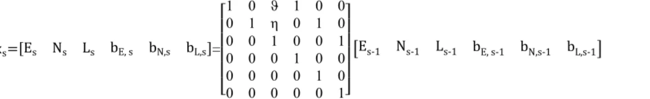
where Ls is the step length of s step; a, b and c are the tuning parameters; H is the height of user; Fs is the walking frequency which is real-time estimated at s step. Furthermore, the position KF is used to estimate the integrated position based on ANN aided image localization and PDR. The innovation equation is based on the difference between two positioning technologies. The state vector of position KF used in this research is shown in the following equation:
xs=[Es Ns Ls bE, s bN,s bL,s]= [ 1 0 ϑ 1 0 0 0 1 η 0 1 0 0 0 1 0 0 1 0 0 0 1 0 0 0 0 0 0 1 0 0 0 0 0 0 1] [Es-1 Ns-1 Ls-1 bE, s-1 bN,s-1 bL,s-1] (24)
where E is the eastern coordinate; N is the northern coordinate; L is the step length; ϑ and η are the second-order of Taylor series expansion for sine and cosine function; bE, k is the offset of eastern direction; bN, k is the offset of northern direction; bL, k is the bias of step length.
3 RESULTS AND DISCUSSIONS
The results are divided into three parts: mapping results, image-based localizations and the proposed integrated system. The subsection of mapping results shows the accuracy of georeferenced images as well as the accuracy of floor plan which produced by portable MMS and UAV MMS, respectively. In addition to mapping results, the comparison between three different distance and position estimations for image-based localization is shown in the next subsection. The position accuracy is compared between different image-based localization methods, and the best method is used for the further integrated system. The final subsection shows the results of proposed indoor navigation system based on the ANN aided image-based localization and PDR in a real indoor environment. All the used check points are surveyed by total station to testify the accuracy. The used smartphone is Sony Z3 (Sony Corporation, Tokyo, Japan), and its specification and calibrated results of the camera are shown in Table 3. The calibrated results provide the accurate IOPs for space resection.
Table 3. The calibrated results and specification of used smartphone camera
3.1 Mapping Results
The accuracy analysis of georeferenced image which produced by portable MMS is shown in Figure 14. The analysis compares the ground coordinates of 18 check points which are measured by georeferenced image and surveyed by total station. The red, green and blue lines are the eastern, northern and height error of each check point, respectively. The maximum error is about 1.2 meters, RMSE of the three-dimensional (3D) accuracy of all the check points is about 0.38 meters.
Figure 14. The accuracy analysis of georeferenced image
0 2 4 6 8 10 12 14 16 18 -1.4 -1.2 -1 -0.8 -0.6 -0.4 -0.2 0 0.2 0.4 0.6 Check point ID E rro r (m)
Accuracy analysis of georeferenced image
Eastern error Northern error Height error
The raw scanned result and the smoothed result by RTS are shown in Figure 15(a). The floor plan generated by smoothed scanned result and map rectification is shown in Figure (15b), which produced by UAV MMS. Since the experimental field is a long and narrow building in a north-south direction, the floor plan has been rotated for illustration (vertical axis is ease direction). The accuracy analysis of the raw floor plan and the corrected floor plan is shown in Figure 16. The corrected floor plan means the result after map rectification. There are 10 check points in the analysis. Table 4 shows the mean error and RMSE of all the check points. The mean error and RMSE are calculated from the 3D position error of all the check points. These two accuracy indicators have the improvement about 80% after map rectification. Meanwhile, the floor plan has the absolute accuracy at about 1 meter level, which can be used to well demonstrate the indoor navigation solution as well as seamlessly connected to the outdoor world.
Figure 15. The scanned result (a) and floor plan (b) produced by UAV MMS
Figure 16. The accuracy analysis of produced floor plan with check points Table 4. The accuracy analysis of produced floor plan
3.2 Comparison of image-based localizations
The comparison between three localizations based on marker recognition is shown in Figure 17: the red line is the 2D position RMSE based on marker distortion as introduced in section 2.2.1; the green line is the 2D position RMSE that uses the ANN aided distance estimation as introduced in section 2.2.2; the blue line is the 2D position RMSE that uses the space resection as introduced in section 2.2.3. Overall, the RMSEs based on 32 check points (testing sample shown in section 2.2.2) of above methods are about 1.485, 0.369 and 0.894 meters, respectively. The check points are different camera position that with different distance in front of the marker. Meanwhile, the angle (θ) between the headings of camera and marker is from 3 to 73 degrees relative to the perpendicular of marker. The localization based on the marker distortion and space resection all have a
1 2 3 4 5 6 7 8 9 10 0 2 4 6 8 10 12 14 Check point ID 3 D p o si ti o n erro r (m)
Accuracy analysis of floor plan
Raw floor plan Corrected floor plan
larger error when the distance between camera and marker becomes longer. It is because the marker distortion becomes obscure and the intersection geometry becomes worse. However, the distance estimation based on the marker distortion still contains hidden information and therefore it is modeled as the input of ANN aided distance estimation. The localization based on ANN aided distance estimation has the best performance, even the distance between camera and marker becomes longer. The space resection method doesn’t better than ANN method even the calibrated IOPs are used. Moreover, space resection requires the initial value of camera position and orientation. This research has tried the initial position from the localization based on the marker distortion, however sometimes the results of space resection are divergent. Because of the worse intersection geometry and fewer control points, the more accurate initial values are needed. This research finally uses the initial position from ANN aided method to maintain the convergence of space resection. In addition, the initial orientation for space resection is provided by orientation sensor. The camera calibration is also important to obtain the accurate IOPs for better estimation of space resection. According to those discoveries, space resection is not suitable for image-based localization that uses the marker recognition. Finally, this research selected the ANN aided image-based localization for further integration.
Figure 17. The accuracy analysis of three kinds of localization based on marker recognition
The further analysis of the constructed ANN model is shown in Figure 18. The purple dots are the sample of check points. When the perpendicular angle relative to the marker is large as well as the distance is short, the error of 2D position become larger. This figure indicates the performance of proposed ANN model for different situations. Therefore, the future work of this research is to collect more samples and identify other impact factors for model improvement. Moreover, the camera distance is limited by the camera resolution at about ten meters since the marker recognition needs the clear data matrix. Therefore, another future work is using ANN for marker recognition. The accurate recognition is expected when the marker is blurred due to longer camera distance. Once the above works are finished, the density of marker distribution in real environment can be reduced.
Figure 18. The characteristic of proposed ANN model
2 3 4 5 6 7 8 9 10 0 0.5 1 1.5 2 2.5
Real distance between the camera and marker (m)
2 D P o si ti o n RM S E (m )
Accuracy analysis of image-based localizations
ANN aiding Space resection Marker distortion 0 20 40 60 80 0 5 10 0 0.5 1 1.5
Relative angle from the perpendicular (degree)
Characteristic analysis of ANN model
Real camera distance (m)
2D pos it ion e rr or ( m ) -0.4 -0.2 0 0.2 0.4 0.6 0.8 1 1.2 1.4 1.6
3.3 Results of Proposed Integrated System
The trajectories of proposed integrated navigation system based on ANN aided image-based localization and PDR are shown in Figure 19: the blue line is the trajectory of PDR; the red line is the trajectory of proposed system; the black point (with an orange box) is the start and end location; the 12 green points are the locations of marker, which are used to do the position update for PDR from ANN aided image-based localization algorithm; the purple points are the check points. The coordinate system is TWD97 (Taiwan Datum 1997), and the solutions are shifted for better illustration.
It is hard for the user to hold the smartphone, accurate sensors, power supply and computer simultaneously, so it is quite difficult to create an accurate reference trajectory. Instead of getting accurate trajectories, we chose the points in the corners as the check points, which can be easily measured on the estimated trajectory. The experimental route is about 650 meters, and similar to the shape of number eight. The test is implemented by three users. The RMSE of check points and the percentage of loop closure error (LCE) are shown in Table 5. The percentage of loop closure error represents the difference between the start and end location divided by the total walking distance for a closed path. For example, a loop closure error of 1% represents one meter of accumulated error for every one hundred meters traveled. However, LCE doesn’t consider the absolute scale and the accuracy of the middle of the trajectory. Therefore, the analysis of check points provided for performance analysis. The results show the significant improvement of proposed integrated system compared to traditional PDR (without model tuning). As shown in Table 5, the proposed system has been test to have the abilities of accurate long-term and seamless navigation with the position RMSE about 4 meters and the percentage of loop closure error about 0.3% after travelled 650 meters. Most importantly, the solution is directly in global coordinate system. The smartphone is the only required device. Meanwhile, there is no need to do any PDR calibration and take image frequently. The used image-based localization has less burden of image processing and longer effective distance compared to traditional image/marker-based localization.
Table 5. The accuracy analysis of proposed indoor navigation system
4 CONCLUSIONS
This research proposes an indoor navigation system based on ANN aided image-based localization and PDR. Firstly, joint operation of MMSs is proposed to collect the necessary information for proposed indoor navigation system: georeferenced image and floor plan. Then the ANN aided image-based localization is trained offline. Finally, the trained ANN is used to provide estimated distance from camera to georeferenced marker in order to help PDR update position in real-time. Therefore, the contributions of this paper include mapping technology and positioning technologies. For mapping technology, the joint operation of MMSs which includes portable cart with panoramic camera and LIDAR-based UAV is proposed to overcome the environmental challenges, and produce the accurate mapping results. Compare to the traditional survey, the proposed procedure is efficient for the construction of floor plan and georeferenced images. Especially, the generated floor plan has accurate absolute scale and global coordinate system for indoor navigation, which make a well demonstration of navigation solution and has an ability of connecting the outdoor world. For proposed indoor navigation system, this research uses the self-designed marker to reduce the burden of image processing. Furthermore, ANN is novel applied for the estimation of the distance between the camera and marker instead of the image recognition or classification. Then, the camera position is accurately estimated based on the estimated distance from ANN, detected georeferenced marker and orientation sensor. Finally, this position is feed to PDR for continuous navigation. In this paper, the proposed system has been test to have the abilities of accurate long-term and seamless navigation with the position error about 4 meters and the percentage of loop closure error about 0.3% after travelled 650 meters. The navigated solution is in the global coordinate system because the use of the georeferenced image. The smartphone is the only required device for the user to initialize and navigate in indoor. In conclusion, the benefits of the proposed system include no need of extra infrastructures, PDR model tuning, camera calibration and successively taking images. The future work will involve the collection of more samples and identification of other impact factors for model improvement. Moreover, ANN for maker recognition is also considered to be the tool in improving the limitation of the camera distance to the marker. The accurate marker recognition is expected to be increased when the marker is blurred with longer camera distance. In addition, the accurate floor plan can be further used to improve the PDR based on the map matching. Once the above works are finished, the density of marker distribution can be further reduced.
ACKNOWLEDGMENTS
The authors would like to acknowledge the financial support through the project (SYC1050121) funded by the Department of Land Administration, Ministry of Interior, Taiwan, as well as all the technical assistances from his advisor, Dr. Kai-Wei Chiang and co-advisor Dr. Hsiu-Wen Chang.
REFERENCES
[1] P. R. Wolf and B. A. DeWitt, Elements of Photogrammetry: with Applications in GIS, Third ed. Boston, MA, USA: McGraw Hill, 2000.
[2] D. Lapucha, "Precise GPS/INS Positioning for Highway Inventory System," M.Sc M.Sc Thesis, Department of Geomatics Engineering, The University of Calgary, Calgary, Canada, 1990.
[3] N. El-Sheimy, "The development of VISAT-A mobile survey system for gis applications," University of Calgary, 1996.
[4] C. C. Goad, "The Ohio State University highway mapping project: the positioning component," in Proceedings of the
47th Annual Meeting of The Institute of Navigation, 1991, pp. 117-120.
[5] C. K. Toth, "R&D of mobile LIDAR mapping and future trends," in Proc. ASPRS Annu. Conf, 2009, pp. 9-13. [6] N. El-Sheimy and K. P. Schwarz, "Kinematic Positioning In Three Dimension Using CCD Technology," in VNIS93
Conference, Ottawa, Canada, 1993, pp. 472-475.
[7] C. K. Toth and D. A. Grejner-Brzezinska, "Performance analysis of the airborne integrated mapping system (AIMS),"
International Archives of Photogrammetry and Remote Sensing, vol. 32, pp. 320-326, 1997.
[8] I. Puente, H. González-Jorge, J. Martínez-Sánchez, and P. Arias, "Review of mobile mapping and surveying technologies," Measurement, vol. 46, pp. 2127-2145, 2013.
[9] C. V. Tao and J. Li, Advances in mobile mapping technology vol. 4: CRC Press, 2007.
[10] F. Keller and H. Sternberg, "Multi-Sensor Platform for Indoor Mobile Mapping: System Calibration and Using a Total Station for Indoor Applications," Remote Sensing, vol. 5, pp. 5805-5824, 2013.
[11] K. W. Chiang, M. L. Tsai, and C. H. Chu, "The development of an UAV borne direct georeferenced photogrammetric platform for Ground Control Point free applications," Sensors (Basel), vol. 12, pp. 9161-80, 2012.
[12] A. Jaakkola, J. Hyyppä, A. Kukko, X. Yu, H. Kaartinen, M. Lehtomäki, et al., "A low-cost multi-sensoral mobile mapping system and its feasibility for tree measurements," ISPRS Journal of Photogrammetry and Remote Sensing, vol. 65, pp. 514-522, 2010.
[13] C. Ellum and N. El-Sheimy, "The development of a backpack mobile mapping system," Int. Arc. Photogrammetry
and Remote Sense, vol. XXXIII, pp. 184 -191, 2000.
[14] A. Oliver, S. Kang, B. C. Wünsche, and B. MacDonald, "Using the Kinect as a navigation sensor for mobile robotics," in Proceedings of the 27th Conference on Image and Vision Computing New Zealand, 2012, pp. 509-514. [15] T. Oh, D. Lee, H. Kim, and H. Myung, "Graph structure-based simultaneous localization and mapping using a hybrid
method of 2D laser scan and monocular camera image in environments with laser scan ambiguity," Sensors, vol. 15, pp. 15830-15852, 2015.
[16] B. Okorn, X. Xiong, B. Akinci, and D. Huber, "Toward automated modeling of floor plans," in Proceedings of the
symposium on 3D data processing, visualization and transmission, 2010.
[17] M. Montemerlo, S. Thrun, D. Koller, and B. Wegbreit, "FastSLAM: A factored solution to the simultaneous localization and mapping problem," in Aaai/iaai, 2002, pp. 593-598.
[18] G. Grisetti, C. Stachniss, and W. Burgard, "Improved techniques for grid mapping with rao-blackwellized particle filters," IEEE transactions on Robotics, vol. 23, pp. 34-46, 2007.
[19] R. Mautz, "Indoor Positioning Technologies," Habilitation Thesis, ETH Zurich, Department of Civil, Environmental and Geomatic Engineering, Institute of Geodesy and Photogrammetry, Eidgenössische Technische Hochschule Zürich, Zurich, Switzerland, 2012.
[20] R. Harle, "A Survey of Indoor Inertial Positioning Systems for Pedestrians," IEEE Commun. Surveys Tutor., vol. 15, pp. 1281-1293, 2013.
[21] J. Liu, R. Chen, L. Pei, R. Guinness, and H. Kuusniemi, "A hybrid smartphone indoor positioning solution for mobile LBS," Sensors (Basel), vol. 12, pp. 17208-33, 2012.
[22] N. E. Klepeis, W. C. Nelson, W. R. Ott, J. P. Robinson, A. M. Tsang, P. Switzer, et al., "The National Human Activity Pattern Survey (NHAPS): A Resource for Assessing Exposure to Environmental Pollutants," Journal of
Exposure Analysis and Environmental Epidemiology, vol. 11(3), pp. 231-252, 2001.
[23] P. Nunez, R. Vazquez-Martin, and A. Bandera, "Visual odometry based on structural matching of local invariant features using stereo camera sensor," Sensors (Basel), vol. 11, pp. 7262-84, 2011.
[24] E. Deretey, M. T. Ahmed, J. A. Marshall, and M. Greenspan, "Visual indoor positioning with a single camera using PnP," in 2015 International Conference on Indoor Positioning and Indoor Navigation (IPIN), Banff, Alberta, Canada, pp. 1-9.
[25] D. Grießbach, D. Baumbach, and S. Zuev, "Stereo-vision-aided inertial navigation for unknown indoor and outdoor environments," Busan, Korea, pp. 709-716.
[26] J. Kim and H. Jun, "Vision-based location positioning using augmented reality for indoor navigation," IEEE
Transactions on Consumer Electronics, vol. 54, 2008.
[27] A. Mulloni, D. Wagner, I. Barakonyi, and D. Schmalstieg, "Indoor positioning and navigation with camera phones,"
IEEE Pervasive Computing, vol. 8, 2009.
[28] X. Li, J. Wang, and T. Li, "Seamless positioning and navigation by using geo-referenced images and multi-sensor data," Sensors (Basel), vol. 13, pp. pp. 9047-9069, 2013.
[29] F. M. Ham and I. Kostanic, Principles of neurocomputing for science and engineering: McGraw-Hill Higher Education, 2000.
[31] M. Meng and A. C. Kak, "Mobile robot navigation using neural networks and nonmetrical environmental models,"
IEEE Control Systems, vol. 13, pp. 30-39, 1993.
[32] K. W. Chiang, "INS/GPS Integration Using Neural Networks for Land Vehicular Navigation Applications," Degree of Doctor of Philosophy, Department of Geomatics Engineering, University of Calgary, Calgary, Alberta, Canada, 2004. [33] M. Gholami, N. Cai, and R. Brennan, "An artificial neural network approach to the problem of wireless sensors
network localization," Robotics and Computer-Integrated Manufacturing, vol. 29, pp. 96-109, 2013.
[34] M. Altini, D. Brunelli, E. Farella, and L. Benini, "Bluetooth indoor localization with multiple neural networks," in
Wireless Pervasive Computing (ISWPC), 2010 5th IEEE International Symposium on, 2010, pp. 295-300.
[35] M. Moreno-Cano, M. A. Zamora-Izquierdo, J. Santa, and A. F. Skarmeta, "An indoor localization system based on artificial neural networks and particle filters applied to intelligent buildings," Neurocomputing, vol. 122, pp. 116-125, 2013.
[36] C. Toth, D. A., Grejner-Brzezinska, and S. Moafipoor, "Pedestrian Tracking and Navigation Using Neural Networks and Fuzzy Logic," Alcala de Henares, 2007, pp. 1 - 6.
[37] S. Saeedi, "Context-Aware Personal Navigation Services Using Multi-level Sensor Fusion Algorithms," PhD,
University of Calgary, 2013.
[38] G. Kim and E. M. Petriu, "Fiducial marker indoor localization with artificial neural network," in 2010 IEEE/ASME
International Conference on Advanced Intelligent Mechatronics, 2010, pp. 961-966.
[39] D. O. Sales, P. Shinzato, G. Pessin, D. F. Wolf, and F. S. Osorio, "Vision-based autonomous navigation system using ann and fsm control," in Robotics Symposium and Intelligent Robotic Meeting (LARS), 2010 Latin American, 2010, pp. 85-90.
[40] B. Agata and H. Robert, "Walk detection and step counting on unconstrained smartphones," Zurich, Switzerland, pp. 225-234.
[41] H. Weinberg, "Using the ADXL202 in Pedometer and Personal Navigation Applications," Norwood, MA, USA, 2002. [42] N. H. Ho, P. H. Truong, and G. M. Jeong, "Step-Detection and Adaptive Step-Length Estimation for Pedestrian
Dead-Reckoning at Various Walking Speeds Using a Smartphone," Sensors (Basel), vol. 16, 2016.
[43] P. D. Groves, G. W. Pulford, C. A. Littlefield, D. L. J. Nash, and C. J. Mather, "Inertial Navigation Versus Pedestrian Dead Reckoning Optimizing the Integration," Fort Worth, TX, USA.
[44] K.-P. Schwarz, M. Chapman, M. Cannon, and P. Gong, "An integrated INS/GPS approach to the georeferencing of remotely sensed data," Photogrammetric engineering and remote sensing, vol. 59, pp. 1667-1674, 1993.
[45] D. B. Allison, J. L. Mentore, M. Heo, L. P. Chandler, J. C. Cappelleri, M. C. Infante, et al., "Antipsychotic-induced weight gain: a comprehensive research synthesis," American journal of Psychiatry, vol. 156, pp. 1686-1696, 1999. [46] R. Chen, L. Pei, and Y. Chen, "A Smart Phone Based PDR Solution for Indoor Navigation," Portland, OR, USA, pp.