Abstract
Vehicular Ad-Hoc Network (VANET) is surging in popularity, in which vehicles constitute the mobile nodes in the network. Due to the prohibitive cost of deploying and implementing such a system in real world, most research in VANET relies on simulations for evaluation. A key component for VANET simulations is a realistic vehicular mobility model that ensures conclusions drawn from simulation experiments will carry through to real deployments. However, VANET simulations raise many new questions about suitable levels of details in simulation models for nodes mobility. In VANET simulations, the mobility models used affect strongly the simulation output. The researchers need to decide what level of details are required for their simulations. In this work, we introduce a tool MOVE that allows users to rapidly generate realistic mobility models for VANET simulations. MOVE is built on top of an open source micro-traffic simulator SUMO. The output of MOVE is a realistic mobility model and can be immediately used by popular network simulators such as ns-2 and qualnet. We show that the simulation results obtained when using a realistic mobility model such as MOVE are significantly different from results based on the commonly used random waypoint model. In addition, we evaluate the effects of details of mobility models in three case studies of VANET simulations (specifically, the existence of traffic lights, driver route choice and car overtaking behavior) and show that selecting sufficient level of details in the simulation is critical for VANET protocol design.
Keyword: VANET, Mobility, Simulation
Table of Contents
1. 前言...5
2. 目的...6
3. 研究方法...7
3.1 MAP Editor...8
3.2 Vehicle Movement Editor...10
4. 結果與討論...13
A. Existence of traffic lights ...14
B. Driver route choice...16
C. Overtaking behavior ...18
5. 相關研究...20
A. Mobility models ...20
B. VAENT simulators...21
6. 成果發表...23
6.1. 會議論文...23
6.2. 期刊論文...23
6.3. 海報(Poster)...23
7. 結論...24
參考資料...25
List of Figures
Figure 1. The architecture of MOVE ...6
Figure 2. Mobility Model Generator...7
Figure 3. Visualization of Vehicle movements...8
Figure 4. Traffic Model Generation...8
Figure 5. Road Map Generation...9
Figure 6. Generating realistic map using Google Earth...9
Figure 7. Road Map generation using the Map Editor...10
Figure 8. Vehicle Movement Generation... 11
Figure 9. Bus route generation... 11
Figure 10. Comparison between Random Waypoint and model generated by MOVE ...13
Figure 11. Clustering effect due to the traffic light...14
Figure 12. Effect of traffic light ...15
Figure 13. Effect of inter-traffic-light distance...15
Figure 14. Effect of traffic cycle duration ...16
Figure 15. Effect of driver route choice...17
Figure 16. Evaluation packet delivery ratio in high density network ...18
Figure 17. Effect of car overtaking behavior ...18
Table of Figures
Table 1. Comparison of path characteristics between the shortest path and the fastest
path...17
1. 前言
Vehicular Ad-Hoc Network (VANET) communication has recently become an increasingly popular research topic in the area of wireless networking as well as the automotive industries. The goal of VANET research is to develop a vehicular communication system to enable quick and cost-efficient distribution of data for the be ne f i t of pa s s e nge r s ’ s a f e t y a ndcomfort.
While it is crucial to test and evaluate protocol implementations in a real world environment, simulations are still commonly used as a first step in the protocol development for VANET research. Several communication networking simulation tools already existed to provide a platform to test and evaluate network protocols, such as ns-2 [1], OPNET [2] and Qualnet [3]. However, these tools are designed to provide generic simulation scenarios without being particularly tailored for applications in the transportation environment. On the other hand, in the transportation arena, simulations have also played an important role. A variety of simulation tools such as PARAMICS [4], CORSIM [5] and VISSIM [6] etc have been developed to analyze transportation scenarios at the micro- and macro-scale levels.
However, there was little effort in integrating communication techniques and scenarios in a realistic transportation simulation environment.
One of the most important parameters in simulating ad-hoc networks is the node mobility. It is important to use a realistic mobility model so that results from the simulation correctly reflect the real-world performance of a VANET. A realistic mobility model should consist of a realistic topological map which reflects different densities of roads and different categories of streets with various speed limits.
Another important parameter should be modeled is the obstacles. In the real world, a vehicle node is typically constrained to streets which are separated by buildings, trees or other objects. Such obstructions often increase the average distance between nodes as compared to that in an open-field environment. In addition, each vehicle needs to decide a turning directions at the intersection (e.g. turn left, turn right or go straight).
Such a turning model could have an effect on the congestion of the road as well as on
the clustering of the vehicles. Furthermore, a smooth deceleration and acceleration
model should be considered since vehicles do not abruptly break and move. Some
prior studies [7], [8] have shown that a realistic model is critical for accurate network
simulation results.
2. 目的
Selecting appropriate level of details in the mobility model for a VANET simulation is a critical decision. Unrealistic mobility model can produce simulations that are misleading or incorrect. On the other hand, adding details requires time to implement and debug. In addition, it might increase simulation complexity, slow down simulation, and distract the research problem at hand. In this work, we develop a tool MOVE (MObility model generator for VEhicular networks) to facilitate users to rapidly generate realistic mobility models for VANET simulations. MOVE provides an environment that allows the user to quickly pinpoint incorrect details and manage details overhead. Our tool is built on top of an open source micro-traffic simulator SUMO [9]. The output of MOVE is a mobility trace file that contains information of realistic vehicle movements which can be immediately used by popular simulation tools such as ns-2 or qualnet. MOVE allows users to rapidly generate realistic VANET mobility models in two aspects:- by interfacing with real world map databases such as TIGER (Topologically Integrated GEographic Encoding and Referencing) [10] and Google Earth, MOVE allows the user to conveniently incorporate realistic road maps into the simulation. In addition, by providing a set of Graphical User Interfaces that automate the simulation script generation, MOVE allows the user to quickly generate realistic simulation scenarios without the hassle of writing simulation scripts as well as learning about the internal details of the simulator.
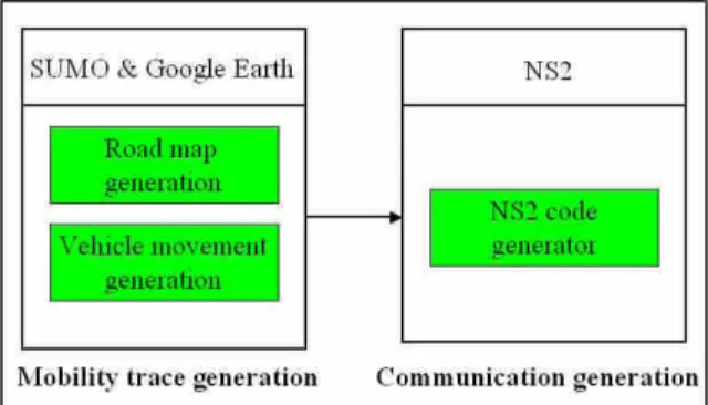
The architecture of MOVE is shown in Figure 1. In this work, we first describe the architecture implementation of MOVE (Section 3). We then compare MOVE against the commonly used random waypoint model and show that a realistic mobility model is critical for VANET simulations. We present three case studies that consider three different scenarios including the existence of traffic light, driver route choice at the intersection, and car overtaking behavior. We discuss how these details affect the network topology and resultingly the performance of VANET in the simulation (Section 4).
Figure 1. The architecture of MOVE
3. 研究方法
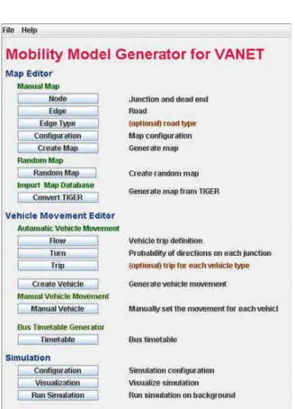
MOVE is currently implemented in Java and runs atop an open-source micro-traffic simulator SUMO. MOVE consists of two main components: the Map Editor and the Vehicle Movement Editor, as shown in Figure 2. The Map Editor is used to create the road topology. Currently our implementation provides three different ways to create the road map –the map can be manually created by the user, generated automatically, or imported from existing real world maps such as publicly available TIGER database from U.S. Census Bureau [10]. The Vehicle Movement Editor allows the user to specify the trips of vehicles and the route that each vehicle will take for one particular trip. We currently support three different methods to define the vehicle movements –the vehicle movement patterns can be manually created by the user, generated automatically, or specified based on a bus time table to simulate the movements of public transport. The information users input in the Map Editor and the Vehicle Movement Editor is then fed into SUMO to generate a mobility trace which can be immediately used by a simulation tool such as ns-2 or qualnet to simulate realistic vehicle movements.
Figure 2. Mobility Model Generator
Users can also visualize the generated mobility trace by clicking on the
“ Vi s ua l i za t i on”button on the main menu, as shown in Figure 3. This is useful for
observing the details o f ve hi c l e move me nt ( e . g. c a r s ’ ove r t a ki ng be ha vi or ) a nd
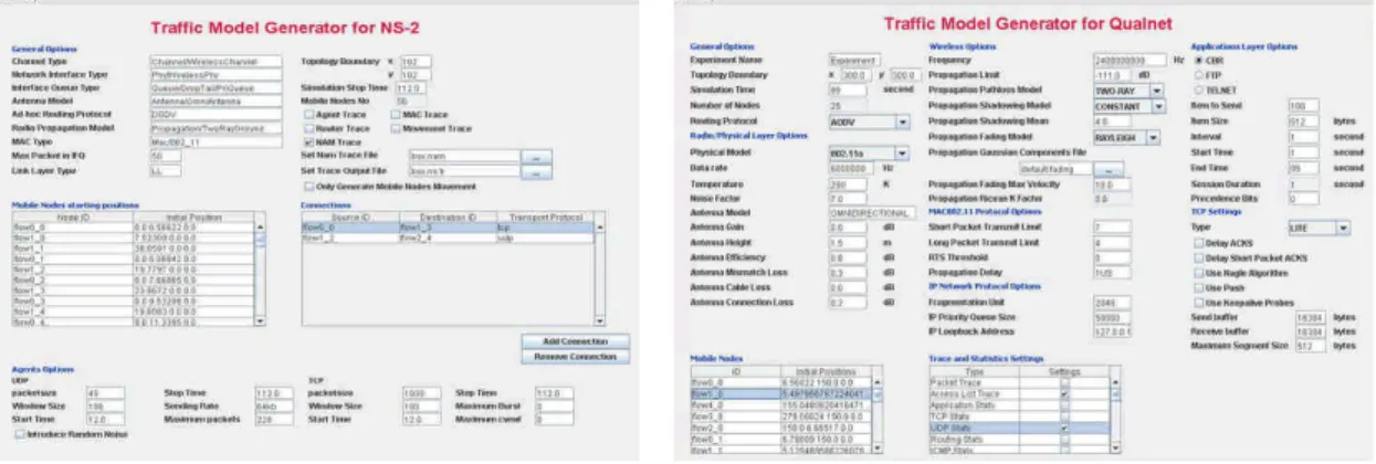
debugging (e.g. to avoid incorrect setting of simulation parameters). Finally, one of the major overhead before one can start conducting research using simulations is to learn about the internal details of the simulator and write customized simulator-specific scripts to generate various simulation scenarios for the research problem under study [11]. To reduce such an overhead, MOVE provides an interface to automatically generate simulation scripts on the fly based on the parameters that the user inputs into MOVE. We currently support auto-generation of ns-2 and qualnet simulation scripts, as shown in Figure 4.
Figure 3. Visualization of Vehicle movements
(a) Traffic model generation for ns-2 (b) Traffic model generation for qualnet
Figure 4. Traffic Model Generation 3.1 MAP Editor
In MOVE, the road map can be generated manually, automatically or imported
from a real world map. Manual generation of the map requires inputs of two types of
information, nodes a nd e dge s . A ” node ” i s one pa r t i c ul a r poi nt on t he ma p whi c h c a n
be either a junction or the dead end of a road. Furthermore, the junction nodes can be
either normal road junctions or traffic lights. The edge is the road that connects two
points (nodes) on a map. The attributes associated with an edge include speed limit,
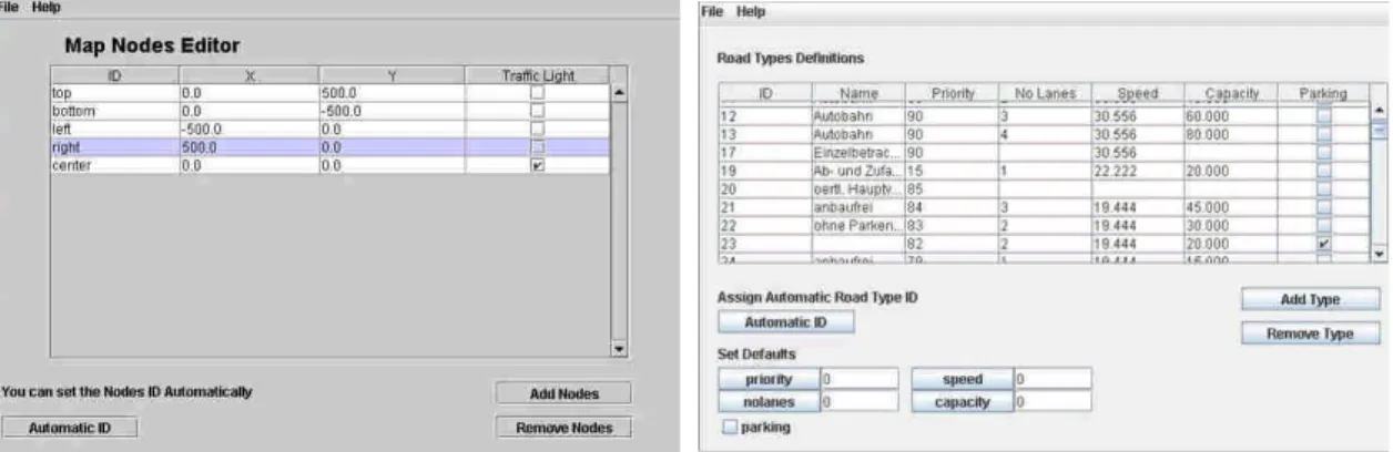
number of lanes, the road priority and the road length. Figure 5 shows snapshots of node editor and edge editor.
(a) Node Editor (b) Edge Editor
Figure 5. Road Map Generation
We have also integrated Google Earth into MOVE to facilitate the creation of nodes in a realistic setting. Google Earth is a tool that enables its user to view the satellite image map of any place on earth. One of the functionality that Google Earth pr ovi de s i s c a l l e d “ pl a c ema r k” whi c h a l l owsthe user to put a mark on any location of the Google Earth map. Each placemark contains the longitude and latitude information of the selected locations and can be saved into a file in KML format [12].
Hence, one can define the node location on the Google map and then extract the node information by processing the saved KML file. This allows MOVE users to generate a map for any real-world road on earth for their simulations. Figure 6 shows an example of using Google Earth to generate nodes for the major intersections in the Eastern Suburb of Sydney.
Figure 6. Generating realistic map using Google Earth
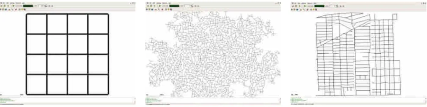
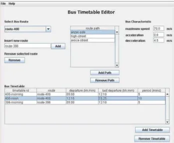
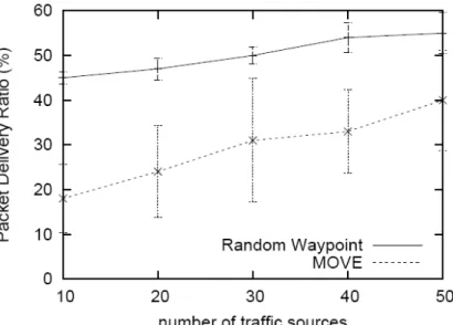
The road map can also be generated automatically without any user input. Three types of random maps are currently available: grid, spider, and random networks.
There are some parameters associated with different types of random maps such as number of grids and the number of spider arms and circles. Finally, one can also generate a realistic map by importing real world maps from publicly available database. We currently support the TIGER maps which are available from U.S.
Census Bureau. Figure 7 shows a grid map generated from the random map generator and a street map in the Houston area based on a TIGER database file.
(a) A grid map (b) A random map (c) A real world map
Figure 7. Road Map generation using the Map Editor 3.2 Vehicle Movement Editor
The movements of vehicles can be generated automatically or manually using the Vehicle Movement Editor. To generate vehicle movement automatically, one needs to first define a vehicle flow which describes a fleet of vehicles toward the same direction. The parameters of each flow consist of the starting road and destination of the vehicle fleet, the time to start and end the vehicle flow, the number of vehicles in the flow and the inter-departure time of the vehicles originating from the starting road.
In addition, a MOVE user can define the probability of turning to different directions at each junction (e.g. 0.5 to turn left, 0.3 to turn right and 0.2 to go straight) in the editor. Figure 8(a) shows a snapshot of the Flow definition Editor.
One can also generate vehicle movement manually using the Vehicle Movement Editor which allows users to specify several properties of vehicle routes including the number of vehicles in a particular route, vehicle departure time, origin and destination of the vehicle, duration of the trip, vehicle speed (including acceleration, deceleration and maximum speed), etc.
Figure 8(b) shows a snapshot of the Vehicle Movement Editor. Note that, in
addition to simulating vehicle-to-vehicle communication, our tool is also useful for
simulations of vehicle-to-infrastructure communication (e.g. the communication
between mobile nodes and road-side static gateway nodes). A static node can be
created in MOVE by assigning the vehicle with a maximum speed of zero in the Vehicle Movement Editor.
(a) Vehicle Flow Generation (b) Vehicle Movement Editor
Figure 8. Vehicle Movement Generation
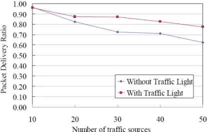
On-board communication has recently become an increasingly popular research topic. A new paradigm of Networks in Motion is quickly attracting interest from the research community and is also being viewed as a viable commercial solution for extending Internet services to public transport passengers. MOVE allows users to enter the bus time table to simulate the movements of public transport. We model buses as a group of vehicles which have similar parameters such as speeds, routes, etc, associated with it as other vehicles. In addition, to model the bus time table, one should define the departure times of the first and the last bus and the bus inter-arrival time (which is assumed to be constant in our implementation). Figure 9 shows the editor for entering the bus route information.
Figure 9. Bus route generation
Mobility models play an important role in VANET simulations. Nodes location,
density, and direction etc. affect VANET performance directly. The objective of
MOVE is to inject as much details as possible into the simulation in order to provide a
mor e “ r e a l i s t i c ” mobi l i t y model. Howe ver , a “ t r ue l y r ea l i s t i c ” s i mul a t i on i s ve r y
challenging due to that human behavior (e.g. mood, sex, age, etc.) and unexpected
road accidents are difficult to model while all of them have strong effects on vehicle
movement patterns. Therefore, simulation designers need to understand what level of
details are relevant to their research questions under study. In this section, we evaluate
the impact of mobility models generated by MOVE on the performance of ad-hoc
routing protocols. The road topology generated by MOVE is based on the TIGER
database data. The propagation model employed in our simulation is the log normal
shadowing model. We used a path loss exponent 2.56 with standard deviation 4.0
based on real-world measurement data from an inter-vehicle experiment previously
carried out in Sydney suburban area [13]. All nodes use 802.11 MAC operating at
2Mbps. The transmission range is 250m.
4. 結果與討論
First, we compared the performance of AODV [14] when a unrealistic mobility model such as the random waypoint model is used to that using the MOVE mobility models. The simulation experiments were carried out in ns-2. Each simulation lasts for 900 seconds. We generated scenarios for 150 nodes moving in an area of 4 square kilometres. We varied the number of source nodes from 10 to 50, each of which is a CBR traffic source transmitting User Datagram Protocol (UDP) packets of a size of 64 bytes at the rate of 4 packets per second.
Figure 10 shows the packet delivery ratio of AODV with different number of traffic sources. Each data point represents the average of six runs and the error bars represent the range of observed packet delivery ratios. Overall, the packet delivery ratios increase as the number of traffic sources increases, which suggest a higher density of nodes can increase the network performance as long as the increasing density does not create more radio interference.
Figure 10. Comparison between Random Waypoint and model generated by MOVE In addition, the packet delivery ratios of AODV based on MOVE mobility models are lower than when the Random Waypoint model is used. The results generated from MOVE also have larger variations. The larger variance in MOVE data points is possibly due to unstable network connectivity imposed by constrained node movements by roads and traffic control mechanisms (such as traffic lights). Figure 10 clearly shows that the simulation results using a more realistic mobility model can be drastically different from that using a simplistic open field model. Note that our results are also consistent with prior work [15].
Second, we evaluate the effects of details of mobility models in three case
studies. Specifically, we set out to understand how the existence of traffic lights, driver route choice and car overtaking behavior affect the VANET simulation results.
The number of nodes in our simulations is 300 and the simulation time lasts for 1000 seconds. The roads created in the simulation have two lanes.
A. Existence of traffic lights
In real world, traffic lights are used to regulate traffic flow moving in different di r e c t i ons . The e xi s t e nc e of t r af f i c l i ght s t e nds t o c r e a t e a “ c l us t er i ng” ef f ec t . I n ot her words, places where there is a traffic light are likely to have a higher node density due to that vehicles are forced to stop at the traffic light to wait for the light to turn green.
Intuitively, a high node density might improve the network connectivity. On the other hand, a higher node density might also suggest a higher chance for packet collision since more nodes might be transmitting at the same time. In addition, the distance between two adjacent traffic lights can have a significant effect on the network c onne c t i vi t y. Spec i f i c a l l y, t he ne t wor k c a n be “ f r a gme nt e d” by t he t r af f i c l i ght s when the radio transmission range is smaller than the distance between two adjacent clusters.
In other words, a link breakage can happen when the inter-cluster distance is larger than the radio coverage.
Figure 11 shows the distribution of the number of neighboring nodes when ten traffic lights are included in the simulations. Our results show that each node has twice the number of neighboring nodes when traffic lights are simulated, as compared to the case when traffic lights are not simulated. Here we define a “ ne i ghbor i ng node ” as the node which is within the radio range of a vehicle. Having a larger number of neighboring nodes typically suggests a better network connectivity.
Figure 11. Clustering effect due to the traffic light
As shown in Figure 12, the packet delivery ratio is improved when the traffic lights are simulated. Note that in this simulation the distance between two adjacent traffic lights is shorter than the given radio range. In addition, we observe that the number of packet collisions increase as we increase the number of traffic sources. As a result, the packet delivery ratio decrease when there are more traffic sources.
Figure 12. Effect of traffic light
To understand the effect of inter-cluster distance on the simulations results, we increase the distance between two adjacent traffic lights (from 200m to 400m) so that the inter-cluster distance is larger than the effective radio distance. As shown in Figure 13, in this scenario we observe frequent link breakage between two adjacent clusters which significant degrade the network performance (in this scenario, the inter-cluster distance is 400m). The effective radio range is around 250m in this experiment.
Figure 13. Effect of inter-traffic-light distance
Finally, we find that the traffic light cycle can also have a significant impact on the network performance. As shown in Figure 14, we observe from simulations that the packet delivery ratio decrease as we increase the traffic light cycle duration (X-axis is the duration of the green light and the red light). While the increased red light cycle increases the cluster size, vehicles are also able to travel farther with a longer green light duration which introduces more link breakage between clusters and results in more packet losses.
Figure 14. Effect of traffic cycle duration B. Driver route choice
In real world, a driver normally has to decide his moving direction at an intersection. He can choose to either go straight, turn left, or turn right. MOVE allows a user to define the turning probability to different directions at each intersection (e.g.
0.5 to turn left,0.3 to go straight and 0.2 to turn left) in the Vehicle Movement Editor.
As shown in Figure 15, we find that different choices of route directions can
significantly change the simulation results (the x-y-z notation in Figure 15 means that
the car has x% of chance to turn left, y% to go straight and z% to turn right).
Figure 15. Effect of driver route choice
In addition, a driver may choose a path based on different criteria such as travel time, distance, habit, etc. People typically tend to choose the path with the shortest distance to their destinations. However, if everybody all choose the “ same”shortest path, it might actually lead to more congestion on the road and longer travel time. On the other hand, a fastest path might not necessarily be the shortest path since a faster path might try to avoid a road segment which is shorter but is more popular.
Intuitively, the choice of a path to the destination could affect nodes density and the network topology as shown in Table I.
Table 1. Comparison of path characteristics between the shortest path and the fastest path
Description The shortest path The fastest travel path
Path choice minimize distance minimum travel time
Node density higher lower
Inter-node distance shorter longer
Probability of having traffic
jam higher lower
As shown in Figure 16, the network performance is better when a popular
shortest path is chosen by all the vehicles. While choosing the same shortest path lead
road congestion, it also creates a network topology with a higher node density. On the
other hand, when choosing a path with the shortest travel time is considered, the
vehicles are more uniformly distributed over the whole area, which results in a more
sparse network topology. Link breakage is more likely to happen in a sparse network
since the inter-node distance is potentially larger. We also observe the packet delivery
ratio is increased as we increase the number of nodes in the simulation which
effectively increases the network density .
0.00 0.10 0.20 0.30 0.40 0.50 0.60 0.70 0.80 0.90 1.00
50 100 150 200 250 300 350
The number of nodes
PacketDeliveryRatio
The shortest path The fastest travel path
Figure 16. Evaluation packet delivery ratio in high density network C. Overtaking behavior
In real world, a faster vehicle can overtake some other slower ones when overtaking is allowed on a multi-lane road. Overtaking behavior can have a great effect on the network topology and should be considered. Specifically, when overtaking behavior is not allowed, it usually results in a chain-like topology and a shorter and uniform inter-vehicle distance (the uniform distance is due to that the vehicle needs to maintain a safe distance from the adjacent cars), which often suggests a better network connectivity. We observe a dramatic impact on the network performance when the overtaking behavior is allowed. In addition, we find that the effect of overtaking behavior is less significant when the network density is higher.
As shown in Figure 17, the packet delivery ratios in overtaking-allowed scenario is close to results of no-overtaking scenario when we increase the number of nodes from 250 to 350.
Figure 17. Effect of car overtaking behavior
In summary, we show that details of mobility models such as the existence of
traffic lights, driver route choice and car overtaking behavior can have a drastic
impact on the VANET simulation results. We argue that the faithfulness of simulation
results is proportional to the realism of the parameters and the models used in the
simulations. Therefore, selecting appropriate level of details in the mobility model for
a VANET simulation is a very important yet challenging task.
5. 相關研究
The details of model could have a critical effect on network simulations. An unrealistic model with insufficient details might produce incorrect results. Heidemann et al. [8] studied how the details of energy and radio propagation models affect the result of sensor network simulations. Zhang et al. [16] used traces taken from UMassDieselNet project [17] to study the effect of mobility models on the performance of DTN. They showed a finer grained route-level model of inter-contact times predict performance much more accurately than the coarser-grained all-bus-pairs aggregated model. This suggests that one must take care in choosing the right level of model granularity when modeling mobility-related measures such as inter-contact times. Complementary to previous studies, in this work we look at the effect of model details on VANET simulations. Our work mainly builds on prior work in MANET mobility models and VANET simulators.
A. Mobility models
Random WayPoint (RWP) [18] is an earlier mobility model widely used in MANET simulation [19], [20], [21], [22]. RWP assumes that nodes can move freely in a simulation area without considering any obstacle. However, in a VANET environment vehicles are typically restricted by streets, traffic lights and obstacles.
Hong et al. [23] proposed a Reference Point Group Mobility (RPGM) model to characterize the relationship between mobile hosts. Bettstetter et al. [24] present a Random Direction Model which introduces a stop-turn-and-go behavior which can mimic the vehicle behavior at the intersections. Camp et al. [25] surveyed different mobility models and divided them into two categories: entity models and group models. Bai et al. [26], [27] did a similar survey and further introduced Freeway and Manhattan mobility models in which car following and overtaking behaviors are included. Saha et al. [7] proposed a macro mobility model based on TIGER map database. This work considers the use of Dijkstra shortest path algorithm to select the path from source to destination. Jardosh et al. [28] present an obstacle mobility model that considers the placement of obstacles in the simulation and discussed that the effect of obstacles on the signal propagation. Stepanov et al. [29] described a spatial model that considered path selection and user movement dynamics (such as road congestion and carfollowing behavior). Japp et al. [30] present a city mobility model that is based IDM (Intelligent-Driver Model). Treiber et al. [31] discussed a model that support car turning at the intersections. Zimmermann et al. [32] proposed a mobility model for urban environments where the paths are computed based on Voronoi graphs and the vehicles movement is constrained by the computed paths.
Street RAndom Waypoint (STRAW) [15] model considered traffic light control and
car following. It uses shortest path algorithm to calculate movement path. Mahajan et al. [33] discussed Stop Sign Model (SSM), Probabilistic Traffic Sign Model (PTSM), and Traffic Light Model (TLM) in the context of a traffic control system. In SSM, every vehicle stops at the stop sign for a fixed duration time. PTSM use a probability p to decide if the vehicle needs to stop at the intersection. In TLM, traffic from different directions are considered for adjusting traffic light cycle to minimize the road congestion. Potnis [34], [33] showed that a simpler SSM model could have significantly different results as compared to a more sophisticated PTSM model.
Marfia et al. [35] employed a similar approach as ours. They used CORSIM [5]
TRANSIMS [36] generate different mobility traces which can be used in Qualnet.
Finally, Baumann et al. [37] proposed two mobility models. One uses vectorized street information from the Swiss Geographic Information System (GIS). The other is based on a microscopic, multi-agent traffic simulator (MMTS) [38] to generate vehicle movement traces. In the GIS-based mobility model, the actual node movement is generated according to the random trip model [39] on the vectorized street map. MMTS models the behavior of people living in the area and the travel plan of each individual as well as road congestion situation are considered in the simulation. This trace-based model, while imitating reality closely, requires a high amount of computing power for generation of traces.
B. VAENT simulators
Groovesim [40] is a topography-accurate street-map based vehicle network simulator and is based on GrooveNet, a geographic routing protocol for vehicular networks. It provides several different modes of operation. In Drive Mode, GrooveSim can process data from a GPS unit to provide a real-time map of the ve hi c l e ’ s c ur r e nt l oc a t i on. I t c a n a l s o be us e d as a n e mul a t or i nHybrid Simulation Mode where real vehicles on the road and virtual vehicles in the simulation can interact with each other. Groovesim also provides a tool for analyzing the simulation results. One limitation of Groovesim is that it is strongly tied to one specific routing protocol (i.e. GrooveNet), which limits its use for simulating other routing protocols in a VANET environment. In addition, GrooveSim does not provide mobility traces for network simulators.
STRAW is an extension of SWANS (Scalable Wireless Ad Hoc Network
Simulator) [41], a Java-based simulator for wireless simulations. STRAW contains
simulation tools for generating mobility models and traffic models and is also able to
use real street maps like TIGER data to build the road topology. However, currently
the mobility models can be supported by STRAW is limited. For example, while
STRAW supports multiple lanes, the vehicles are not allowed to change lane and the
starting position is not configurable. Another drawback of this tool is its dependency on SWANS. Finally, STRAW does not provide any GUI that allows the users to visualize the movements of cars.
BonnMotion [42] is a simple tool that can be used to create and analyses mobility
scenarios. Similar to MOVE, the mobility scenarios created by BonnMotion can be
exported to ns-2 and qualnet. However, BonnMotion only models basic motion
constraints and does not consider any micro-mobility. Furthermore, BonnMotion is a
text-based application that runs on a command shell and does not provide any
graphical user interfaces as MOVE does. Complementary to these previous efforts,
our work emphasizes on creating a tool that allows users to rapidly generate realistic
mobility models for VANET simulations.
6. 成果發表 6.1. 會議論文
(A) Kun-chan Lan and Chien-Ming Chou, “ Realistic Mobility Models for Vehicular Ad hoc Network (VANET) Simulations, ” Accepted to appear in ITST2008.
6.2. 期刊論文
(A) Under preparation 6.3. 海報(Poster)
(A) Kun-chan Lan and Chien-Ming Chou, “ On the Effects of Detailed Mobility Models in Vehicular Network Simulations, ” Accepted to appear in MobiQuitous 2008.
(B) Chien-Ming Chou and Kun-chan Lan, “ On the Effects of Detailed Mobility
Models in Vehicular Network Simulations, ” Accepted to appear in MobiCom
2008.
7. 結論
In this work, we first describe a tool MOVE which is based on an open source micro-traffic simulator SUMO. MOVE allows user to quickly generate realistic mobility models for vehicular network simulations. We show that the details of a mobility model such as the existence of traffic lights, driver route choice and car overtaking behavior can have a significant impact on the simulation results. Care should be taken if simple mobility models are used for evaluation of VANET as the results might not be as close to reality as expected. Our next step is to use MOVE to understand the effect of user travel plan (such as path selection, means of transportation, etc) on VANET simulations. We first evaluated congestion significant effect in VANET. The results depicted congestion can increase network performance.
We have made MOVE publicly available and can be downloaded via the
following URL- http://lens1.csie.ncku.edu.tw/MOVE/. In our current implementation,
the movements of vehicles are based on static configurations predefined in the
Vehicle Movement Editor. In other words, the mobility model is first generated
off-line and then used by a network simulator like ns-2. In the next version of our
software, because an accident can change mobility model in any time, we plan to
build an interface to tightly integrate SUMO and ns-2. Such an interface will allow
that vehicle state information (such as location, speed, direction, etc) can be fed into
ns-2 in real time. Hence, during the simulation the vehicles can dynamically adjust
their routes based on different traffic scenarios and communication techniques
employed.
參考資料
[ 1] T. N. S. ns 2, “ ht t p: / / www. i s i . e du/ ns na m/ ns / i nde x. ht ml . ” [ 2] O. Si mul a t or , “ ht t p: / / www. opne t . c om/ . ”
[ 3] Q. N. Si mul a t or , “ ht t p: / / www. s c a l a bl e -n e t wor ks . c om/ . ” [ 4] P. M. T. Si mul a t i on, “ ht t p: / / www. pa r a mi c s -o nl i ne . c om/ . ” [ 5] CORSI M, “ ht t p: / / www. f hwa -t s i s . c om/ . ”
[ 6] P. s i mul a t i on VI SSI M, “ ht t p: / / www. e ngl i s h. pt v. de / . ”
[ 7] A. K. Sa ha a nd D. B. J ohns on, “ Mode l i ng mobi l i t y f or ve hi c ul a r a d hoc ne t wor ks , ” i n VANET 2004, Oct. 2004.
[Online].Available: http://www.cs.rice.edu/∼amsaha/Resume/vanet2004/vanet2004.pdf
[8] J. Heidemann, N. Bulusu, J. Elson, C. Intanagonwiwat, K. chan Lan, Y. Xu, W.
Ye , D. Es t r i n, a nd R. Govi nda n, “ Ef f e c t s of de t a i l i n wi r e l e s s ne t wor k s i mul a t i on, ” i n CNDS 2002, Jan. 2001.
[Online]. Available: http://www.isi.edu/~johnh/PAPERS/Heidemann00d.html
[ 9] S. S. of Ur ba n MObi l i t y, “ ht t p: / / s umo. s our c e f or ge . ne t / . ”
[10] TIGER (Topologically Integrated GEographic Encoding and Referencing),
“ ht t p: / / www. c e ns us . gov/ ge o/ www/ t i ge r / . ”
[ 11] S. Fl oyd a nd V. Pa xs on, “ Di f f i c ul t i e s i n s i mul a t i ng t he I nt e r ne t , ” ACM/IEEE Transactions on Networking, vol. 9, no. 4, pp.
392– 403, Feb. 2001. [Online]. Available: http://www.icir.org/vern/papers.html [ 12] K. t ut or i a l , “ ht t p: / / www. keyhol e . c om/ kml / kml t ut . ht ml . ”
[13] K. chan Lan, G. Setiawan, S. Iskandar, and S. Kanhe r e , “ The e f f ec t of r a di o mode l s on ve hi c l e ne t wor k s i mul a t i ons , ” i n Proc. of the 14th World Congress on Intelligent Transport Systems (ITS), 2007.
[14] C. Perkins, E. Belding-Ro yer , a nd S. Da s , “ Ad hoc on de ma nd di s t a nc e ve c t or ( a odv) r out i ng, ” J ul . 2003,RFC 3561.
[ 15] D. R. Chof f ne s a nd F. E. Bus t a ma nt e , “An i nt e gr a t e d mobi l i t y a nd t r a f f i c mode l f or ve hi c ul a r wi r e l e s s ne t wor ks , ” i n Proc. of the 2nd ACM International Workshop on Vehicular Ad Hoc Networks (VANET), Cologne, Germany, Sep. 2005.
[Online]. Available: http://www.aqualab.cs.northwestern.edu/publications/DChoffnes05vanet.html
[ 16] X. Zha ng, J . Kur os e , B. Le vi ne , D. Tows l ey, a nd H. Zha ng, “ St udy of a bus-based disruption-t ol er a nt ne t wor k: Mobi l i t y mode l i ng a nd i mpac t of r out i ng, ” i n Mobi Com ’ 07,Sep 2007, pp. 195 –206.
[ 17] J . Bur ge s s , B. Ga l l a ghe r , D. J e ns e n, a nd B. N. Le vi ne , “ Ma xpr op: Rout i ng f or vehicle-based disruption-t ol e r a nt ne t wor ks , ” i n IEEE INFOCOM 2006, 2006.
[ 18] B. Da vi d a nd A. Davi d, “ Dyna mi c s our c e r out i ng i n a d hoc wi r e l e s s ne t wor ks , ” in Mobile Computing, vol. 35, Kluwer Academic, 1996, pp. 153– 181.
[ 19] S. R. Da s , C. E. Pe r ki ns , a nd E. M. Roye r , “ Pe r f or ma nc e c ompar i s on of t wo
on-d e ma nd r out i ng pr ot oc ol s f or a d hoc ne t wor ks , ” i n Proc. IEEE Infocom, 2000.
[ 20] G. Hol l a nd a nd N. H. Va i dya , “ Pr oc . mobi c om, a c m i nt e r n. c onf . on mobi l e c omput i ng a nd ne t wor ki ng, ” i n Proc. IEEE Infocom, Aug. 1999.
[ 21] C. E. Pe r ki ns a nd E. M. Royer , “ Ad-hoc on-de ma nd di s t a nce vec t or r out i ng, ” i n Proc. IEEE Workshop on Mobile Computing Systems and Applications, Feb. 1999.
[22] P. Johansson, T. Larsson, N. Hedman, B. Mielczarek, and M. Degermark,
“ Rout i ng pr ot oc ol s f or mobi l e a d-hoc networks - a comparative performance a na l ys i s , ” i n IEEE MOBICOM, 1999, p. 195V206.
[23] X. Hong, M. Gerla, G. Pei, and C.-C. Chi a ng, “ A gr oup mobi l i t y mode l f or a d hoc wi r e l e s s ne t wor ks , ” i n Proc. ACM MSWiM, 1999.
[ 24] C. Be t t s t e t t e r , “ Smoot h i s be t t e r t ha n s ha r p: a r a ndom mobi l i t y mode l f or s i mul a t i on of wi r e l e s s net wor ks , ” i n Proc. MSWiM01, ACM, 2001.
[2 5] T. Ca mp, J . Bol e ng, a nd V. Da vi e s , “A s ur vey of mobi l i t y mode l s f or a d hoc ne t wor k r e s e ar c h, ” i n Wireless Communications and Mobile Computing (WCMC):
Special issue on Mobile Ad Hoc Networking: Research, Trends and Applications, vol.
2, no. 5, 2002, pp. 483– 502.
[ 26] F. Ba i , N. Sa dagopan, a nd A. He l my, “I mpor t a nt : a f r a me wor k t o s ys t e ma t i c a l l y analyze the impact of mobility on performance of routing protocols for ad hoc ne t wor ks , ” i n The 22th IEEE Annual Joint Conference on Computer Communications and Networking INFOCOM 2003, 2003, pp. 825– 835.
[ 27] F. Ba i , N. Sa dagopa n, a nd A. He l my, “ The i mpor t a nt f r a me wor k f or a na l yzi ng t he i mpa c t of mobi l i t y on pe r f or ma nc e of r out i ng f or a d hoc ne t wor ks , ” AdHoc Networks Journal - Elsevier Science, vol. 1, no. 4, pp. 383– 403, Nov. 2003.
[28] A. P. Jardosh, E. M, Belding-Ro yer , K. C. Al me r ot h, a nd S. Sur i , “ Re a l -world e nvi r onme nt mode l s f or mobi l e ne t wor k e va l ua t i on, ” Ma r . 2005.
[29] I. Stepanov, P.-J . Ma r r on, a nd K. Rot he r me l , “ Mobi l i t y mode l i ng of out door scenarios for ma ne t s , ” i n Proc. of the 38th annual Symposium on Simulation ANSS ’ 05,Apr. 2005, pp. 312–322.
[ 30] M. B. Sve n J a a p a nd L. Wol f , “ Eva l ua t i on of r out i ng pr ot oc ol s f or ve hi c ul a r ad hoc ne t wor ks i n c i t y t r af f i c s c e na r i os , ” i n Proc. of the 5th International Conference on Intelligent Transportation Systems Telecommunications (ITST), 2005.
[ 31] M. Tr e i be r , A. He nne c ke , a nd D. He l bi ng, “Conge s t e d t r a f f i c s t a t e s i n e mpi r i c a l obs e r va t i ons a nd mi c r os copi c s i mul a t i ons , ” IPhys. Rev., vol. 62, no. 2, Aug. 2000.
[32] H.-M. Zi mme r ma nn, I . Gr uber , a nd C. Roman, “ A vor onoi -based mobility model f or ur ba n e nvi r onme nt s , ” i n Proc. of the European Wireless 2005 (EW05), Apr. 2005.
[ 33] A. Ma ha j a n, N. Pot ni s , K. Gopa l a n, a nd A. A. Wa ng, “ Ur ba n mobi l i t y mode l s
f or va ne t s , ” i n Proc. of the IEEE Workshop on Next Generation Wireless Networks
(WoNGeN), Dec. 2006.
[ 34] N. Pot ni s a nd A. Ma ha j a n, “ Mobi l i t y mode l s f or ve hi c ul a r a d hoc ne t wor k s i mul a t i ons , ” i n proc. of the 44th annual Southeast regional conference, ACM, 2006, pp. 746– 747.
[35 ] G. Ma r f i a , G. Pa u, E. Gi or da no, E. D. Se na, a nd M. Ger l a , “ Eva l ua t i ng ve hi c l e network strategies for downtown portland: Opportunistic infrastructure and i mpor t a nc e of r e a l i s t i c mobi l i t y mode l s , ” i n proc. of MoBiOpp 2007, co-located with ACM/USENIX International Conference on Mobile Systems, Applications, and Services (MobiSys 2007), Jun. 2007.
[ 36] TRANSI MS: , “ ht t p: / / t r a ns i ms . t s a s a . l a nl . gov/ . ”
[ 37] R. Ba uma nn, S. He i ml i c he r , a nd M. May, “ Towa r ds r e a l i s t i c mobi l i t y mode l s f or vehicular ad-h oc ne t wor ks , ” in 2007 Mobile Networking for Vehicular Environments, May 2007, pp. 73– 78.
[ 38] B. Ra ney, N. Ce t i n, A. Vol l my, M. Vr t i c , K. Axha us e n, a nd K. Nage l , “ Towa r ds a mi c r os c opi c t r a f f i c s i mul a t i on of a l l of s wi t ze r l a nd, ” i n ICCS 2002, 2002, pp.
371– 380.
[39] J.-Y. L. Boudec a nd M. Voj novi c , “ Pe r f e c t s i mul a t i on a nd s t a t i ona r i t y of a c l a s s of mobi l i t y mode l s , ” i n IEEE Infocom, 2005.
[40] R. Mangharam, D. S. Weller, D. D. Stancil, R. Rajkumar, and J. S. Parikh,
“ Gr oove Si m: A t opogr aphy-accurate simulator for geographic routing in vehicular ne t wor k, ” i n Proc. of the 2nd ACM International Workshop on Vehicular Ad Hoc Networks (VANET), Cologne, Germany, Sep. 2005.
[Online]. Available: http://www.andrew.cmu.edu/