Aging effects on interfacial reactions between Sn-9Zn+Cu alloys and Au substrate
Wei-kai Liou and Yee-wen Yen*
Graduate Institute of Materials Science and Technology, National Taiwan University of Science and Technology
*Email: [email protected].
Abstract
This study investigates the aging effects on interfacial reactions between Sn-9Zn+Cu alloy and Au substrate. The Au3Zn7/AuZn2/AuZn and Au3Zn7/AuZn phases respectively formed in the Sn-9Zn/Au and Sn-9Zn+1wt%
Cu/Au systems aged at 160°C for 24 hours. Only the AuSn phase was found at the Sn-9wZn+4wt%Cu/Au interface.
Extending the aging time to 800 hours, Sn became a dominant diffusion element. The binary Au-Sn phases and AuSnZn ternary phase, Au33-36Zn35-36Sn29-31 were formed at the interface. This ternary phase might be the metastable phase. Increasing Cu content in the Sn-9Zn solder to 7-10wt%, the AuSn and (Cu,Au)Sn phases were observed at the solder/Au interface for 24 hour. Aging for 800 hours, the Sn-Zn+Cu/Au systems completely became the Cu-Sn/
Au systems. The AuSn/Cu6Sn5 and AuSn/(Cu,Au)Sn /Cu6Sn5 multi-layers were formed in both Sn-9Zn+7wt%
Cu/Au and Sn-9Zn+10wt%Cu/Au systems. The aging effect causing the changes of dominant diffusion element and concentration of Zn, Cu in the solder is the main reasons to change the sequence of the IMC formation in the (Sn-9Zn)+Cu/Au systems.
Keywords: aging effect, interfacial reaction, Sn-9Zn+Cu alloy, ternary phase, metastable phase
1 Introduction
The Au surface finish was a common metallization in electronic packaging. The function of the Au layer is to provide oxidation protection and enhance the wettability.
Recently, the Au stud-bump bonding (SBB) technology has been developed as a very attractive solution for a low-cost flip-chip technology. This technology has several advantages: UBM (under bump metallurgy) process is not necessary, low bumping cost, and fine-pitch and chip-level bumping is possible. [1] Cu is commonly used as the substrate in printed circuit boards. Thus, the Cu/solder/Au sandwich structure becomes wildly using in electronic packaging industry.
Sn-Pb solders were widely used in the micro- electronic products such as solder past or plating. However, the toxicity of lead is harmful to the environment and human health. Therefore, Pb-Sn solders are forbidden to use in the electronic devices and products. [2, 3] The Sn-9 wt%Zn (Sn-9Zn) solder has more potential to replace Sn-Pb solders for its low cost and liquidus temperature.
Recently, some investigations have been revealed that adding Cu into the Sn-9Zn can improve its poor wettability and enhance anti-oxidation properties. [4] Thus, these efforts make the real use of the Sn-9Zn solder come true.
Kao et al. [5] investigated the interfacial reaction of Sn-xZn/Cu system and reported that the Zn concentration strongly influenced the reaction. Suganuma and Kim [6]
investigated the Sn-9Zn/Cu system. They found that the Cu-Zn intermetallic compounds (IMCs) were unstable when reaction temperatures were above 150°C. Sn is a dominant diffusion specimen in Sn-9Zn/Cu system. Yen and Liou [7] found changing the concentration of Cu in the Sn-9Zn solder dramatically changed the formation of intermetallic compounds in the Sn-9Zn+xCu/Ni system.
Yen and Liou [8] studied the Sn-xZn/Au systems. They found that the evolution of IMCs in the Sn-Zn/Au couples is very sensitive to the Zn. content in Sn-Zn alloys.
Meanwhile, the ternary Au-Sn-Zn IMC was formed in the Sn-5 wt% Zn/Au couple.
Not only the concentration effect, but also the reaction time might influence IMCs formation and reliability of the solder-joint interface. Therefore, clear understanding of the interface feature and suitable period of aging-treatment is required of the Cu/solder/Au sandwich structure for the application in electronic industries. This study is to investigate aging effects on the interfacial reactions between (Sn-9Zn) + xCu alloys and Au in detail.
2 Experimental
Sn-9 wt%Zn solders containing 1, 4, 7, and 10 wt%
Cu were prepared. The alloy was encapsulated in a quartz tube in vacuum (0.13 N/m2) and placed in a furnace at 900°C for 48 hours for homogenization. After aging, the sample tube was quenched in icy water and dissected into disk-shaped specimens (with a diameter of 6.0 mm with a thickness of 1.0 mm).
The solid/solid state reaction couples were prepared.
Two (Sn-9Zn)+xCu alloy disks and one Au piece of 3.5 mm×3.5 mm×100 μm were sandwiched together using two stainless steel screws. The schematic diagram of the reaction couple is similar to that in a previous work [9].
Boron nitride powders were sprayed on the screws to prevent reactions between the steel and (Sn-9Zn)+xCu alloy. The (Sn-9Zn)+xCu/Au/(Sn-9Zn)+xCu sandwich fixed with screws was encapsulated in an evacuated quartz tube and placed in a furnace aged at 160°C for 6, 24, 72, 144 ,500 and 800 hours respectively. After the reaction, the reaction couple was then quenched in icy water.
The sample was first examined metallurgically.
Optical-microscopy (OM) and scanning electron microscopy (SEM) were used to observe the surface morphology. SEM with energy dispersion spectrometer (EDS) and electron probe micro-analyzer (EPMA) were used to determine the compositions of the IMC that were formed on the solder and solder/substrate interface.
3 Results and discussion
3.1 Aging effects on (Sn-9Zn) + pCu/Au systems (p<3 wt%)
Figure 1(a) presents the backscattered electron image (BEI) micrograph of the Sn-9Zn/Au couple aging at 160 oC
for 24 hours. Three IMC layers were found at the Sn-9Zn/Au interface. According to EPMA analysis, the composition of the phase close to the Au side was Au-25.8 wt %Zn and it was the AuZn phase [10]. The phase close to the solder side with the composition of Au-42.7 wt%Zn was the Au3Zn7 phase [10]. The micro-island shape phase spreading over the solder was also the Au3Zn7 phase. The composition of the third phase between Au3Zn7 and AuZn phases was Au-31.3Zn (in wt% in the text) and it was likely to be the AuZn2 phase [10]. Fig. 1(b) shows a schematic diagram of the interfacial reaction mechanism in the Sn–9Zn/Au couple. In Fig 1(b), JAu and JZn respectively mean the flux of Au and Zn atoms. Because the Zn atoms are easily segregated and accumulated at the solder/Au interface and the Au atoms diffused toward the solder side, Au atoms react with Zn atoms at the Sn-Zn/Au interface to form Au-Zn binary IMCs. Thus, the AuZn, AuZn2, and Au3Zn7 phases were observed at the solder/Au interface.
Figure 2(a) presents the BEI micrograph of Sn-9Zn /Au couple aged at 160°C for 800 hours. Four IMC layers were observed in Fig. 2(a). The composition of the IMC layer on the solder side is Au-18.4Zn-27.9Sn. It was marked as the ternary AuSnZn phase with the chemical formula of Au33-36Zn35-36Sn29-31. Three IMC layers, Au-37.7Sn (bright), Au-54.5Sn (gray) and Au-70.6Sn (dark) were formed between Au and T phase and they were AuSn, AuSn2 and AuSn4 phase. [10] The Zn atoms were consumed to form the Au-Zn IMCs at initial reaction stage.
Thus, the Zn atoms can not supply to the solder/substrate interface from the solder. However, the Sn atoms can continuously diffuse toward the Au side through Au-Zn layers as increasing the aging time. Thus, the Sn reacted with Au to form the Au-Sn IMCs. The Au-Zn IMCs completely transferred to the AuSnZn ternary IMC. The thickness of Au-Zn IMCs in Fig. 1(a) is about 20 μm. This value is very similar to that of the AuSnZn phase, as show in Fig. 2(a).
Something different happens at the solder/Au interface as adding Cu content to Sn-9Zn solder reacting with the Au. Figure 3(a) shows the BEI micrograph of the Sn-9Zn+1 wt% Cu/Au couple aging at 160°C for 24 hours.
From the EPMA analysis, the compositions of the two IMC layers were Au-42.5Zn (gray and thick) and Au-25.2Zn (bright and thin), as shown in Fig. 2(a). They were likely to
be the Au3Zn7 and AuZn phases [10]. Meanwhile, the micro-island-shape phase was found in the solder. This phase had a unique composition of Au-9.2Cu-43.0Zn. It should be the Au3Zn7 phase with 9.2 wt% solubility of Cu [10], and it was labeled as the (Au,Cu)3Zn7 phase. The Zn atoms reacted with the Cu atoms to form the (Au,Cu)3Zn7
phase in the solder. Thus, a value of JZn decreased to cause only two Au-Zn IMCs, Au3Zn7 and AuZn phases, to form at the solder/substrate interface.
Figure 4(a) shows the BEI micrograph of the Sn-9Zn+1 wt%Cu/Au couple aging at 160°C for 800 hours.
Three IMC layers, AuSnZn ternary phase of Au-18.2Zn-27.5Sn, AuSn phase of Au-37.0Sn, and AuSn2
phase of Au-54.5Sn were formed from the solder to the Au substrate. The mechanism of the IMC formation was proposed in Fig. 4(b). Similar to Fig. 2 (b), Zn atoms segregated to the Au surface and reacted to Au to form the Au-Zn binary IMCs at initial stage. Since the reaction time was prolonged, Zn atoms were completely consumed. The Sn and Au atoms became dominate diffusion elements in this system. The Sn and Au atoms, JSn and JAu, continuously diffused toward interfaces with long period of aging time to induce the formation the Au-Sn IMCs and the Au-Zn IMCs converse into the AuSnZn phase.
3.2 Aging effects on (Sn-9Zn) + 4Cu/Au system
The BEI micrograph of Sn-Zn+4 wt% Cu solder reacted with Au at 160°C for 24 hours is shown in Figure 5(a). The AuSn phase with a planar layer of Au-36.9Sn was found at the interface [10]. An irregularly shaped region of Cu-58.0Zn was observed in the solder and it was likely the Cu5Zn8 phase [10]. Because most Zn atoms are consumed to form Cu5Zn8 phases at the solder with increasing the aging time, no Zn atoms can participate in the interfacial reaction at initial reaction stage. However, the Au and Sn atoms continuously diffuse toward interfaces with increasing the aging time, as shown in Fig 5(b). Therefore, the IMC evolution mode at the Sn-Zn+4 wt% Cu/Au couple is more like the Sn/Au system.
The surface morphology of the Sn-9Zn+4 wt%Cu/Au couple aging at 160°C for 800 hours is shown in Figure 6(a). From the EPMA analysis, the composition of the layer close the Au substrate side was Au-50.4Sn and it was AuSn phase. The composition of the layer close to the solder side
was Au-18.5Sn-28.6Zn and it was the ternary AuSnZn phase [8]. A gray layer phase between the AuSn and ternary AuSnZn phases was AuSn2 phase of Au-54.5Sn.
Fig. 6(b) shows that the Sn and Au atoms, JSn and JAu, continuously diffuse toward interfaces with long period of aging time. Adding more Cu to the Sn-Zn solder seems to reduce the Zn segregation rate on the Au side and the most Zn atoms react with Cu atoms to form Cu-Zn IMCs in the solder. Hence, the Zn atoms can be stored in the Cu-Zn short-range-ordered (SRO) structure [4]. That’s why the Cu5Zn8 phase was found in the solder. Based on the mass balance, entire amount of Cu reacting with Zn to form the Cu5Zn8 phase would consume 6.4 wt%Zn. Thus, 9wt%Zn in the Sn–9Zn solder minus the 6.4wt%Zn. Therefore, only 2.6 wt% Zn remained in the solder. Thus, the Sn atoms could continuously diffuse toward interfaces with long period of aging time and cause the Au-Zn IMCs convert into the Au-Sn IMC and T phase, as shown in Fig. 6(b).
3.3 Aging effects on (Sn-9Zn) + rCu/Au systems (r: 6-10 wt%)
Figure 7(a) shows the BEI micrograph of the Sn-9Zn+7 wt% Cu/Au couple aging at 160°C for 24 hours.
The planar layer was found at the solder/Au interface with a composition of Au-36.7Sn and it was the AuSn phase [10]. Two kinds of irregular-shaped regions were also observed in the solder. One region has a unique composition of Cu-59.6Zn and it was Cu5Zn8 phase [10].
The another one which attached to the interface, had a unique composition of Cu-7.5Au-49.3Sn, labeled as the (Cu,Au)Sn phase. [10, 11] Since Zn atoms were completely consumed, the Sn and Au atoms became dominate diffusion elements in this system. Fig. 7(b) indicates that the Au and Sn atoms continuously diffuse toward the interfaces with aging time. Once more than 6 wt% Cu were added into the Sn-9Zn solder, the Cu atoms could rapidly react with Zn atoms to form the Cu-Zn IMC in the solder.
The entire Zn element in the solder is completely consumed to form the Cu5Zn8 phase. Then, the excess Cu atoms move and segregate to the Au side and react with Sn and Au.
Thus, the solder/Au interface then becomes the Sn-Cu/Au system. Therefore, the (Cu,Au)Sn was observed spreading over the interface.
Figure 8(a) shows the BEI micrograph of the
Sn-9Zn+7 wt% Cu/Au couple aging at 160°C for 800 hours.
The composition of the IMC close to the Au side was Au-36.9Sn and it was the AuSn phase. [10] The composition of the IMC close to the solder side was Cu-3.5Au-60.5Sn and it was Cu6Sn5 phase. [9] Fig. 8(a) also shows three kinds of phases were found in the solder.
The composition of dark phase was Cu-62.5Zn and it was Cu5Zn8 phase. [9] The gray region was the Cu6Sn5 phase of Cu-2.1Au-60.7Sn. [10] The irregularly phase close to the interface was the (Cu,Au)5Zn8 phase with composition of Cu-13.1Au-58.5Zn. [9] As the aging time was prolonged, Cu atoms continuously diffuse toward interfaces and then the (Cu, Au)Sn phase would transform into the Cu6Sn5
phase, as shown in Fig. 8(b).
Figure 9(a) shows the BEI micrograph of the Sn-Zn+10wt%Cu/Au system aging at 160°C for 24 hours.
Once 10 wt% Cu was added into the Sn-9Zn solder, two kinds of IMC layer were observed at the interface. The composition of the thicker IMC layer was Au-37.2Sn and it was the AuSn phase. [10] The composition of the thin IMC layer was Cu-13.7Au-49.9Sn, labeled as (Cu, Au)Sn phase [10, 11]. The irregularly shaped region could be observed in the solder, its composition was Cu-49.6 wt%Zn and it was the CuZn phase [10]. Fig. 9(b) shows a schematic diagram of the interfacial reaction mechanism in Sn-9Zn+10 wt%Cu/Au couple. The Au and Sn atoms continuously diffuse toward interfaces with increasing aging time. When the Cu content was increased to 10 wt%, enough Cu atoms would react with the Zn atoms. Thus, the excess Cu atoms segregate and diffuse to the Au side. The solder/Au interface reaction mode becomes the Sn–Cu/Au system.
Figure 10(a) shows the BEI micrograph of the Sn-9Zn+10 wt% Cu/Au couple aged at 160°C for 800 hours. Three layer IMCs were formed at the solder/Au interface. The composition of the IMC close to the Au side was Au-37.0Sn and it was AuSn phase. [10] The IMC, close to the solder side was the Cu6Sn5 phase of Cu-1.9 Au-60.8Sn. [10] The composition of the IMC, between AuSn and Cu6Sn5 phases was Cu-14.3Au -49.7Sn and it was labeled as the (Cu, Au)Sn phase [10, 11]. Three phases were also found in the solder, as shown in Fig. 10(a). The composition of the dark phase was Cu-50.6Zn and it was the CuZn phase. [10] The composition of the gray phase
was Cu-60.7Sn and it was the Cu6Sn5 phase [10]. The irregularly region was the (Cu,Au)5Zn8 phase with the composition of Cu-11.6Au-61.7Zn [10]. Fig. 10(b) shows the schematic diagram of the interfacial reaction mechanism in Sn-9Zn+10 wt%Cu/Au couple aging at 160°C for 800 hours. As extending aging time, Cu atoms can continuously diffuse toward the interface. Thus, the (Cu,Au)Sn phase would transform into the Cu6Sn5+(Cu, Au)Sn phases at the solder/substrate interface.
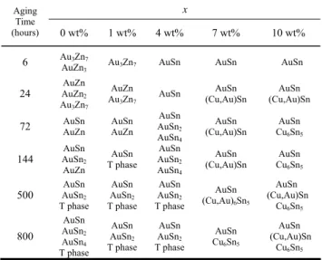
Table I summarizes the evolutions of IMCs at interface in Sn-9Zn+xCu/Au systems aged at 160°C from 6 to 800 hours. The various Cu contents and aging times strongly influence the IMC formation in the Sn-9Zn/Au systems.
4 Conclusion
The Au3Zn7/AuZn2/AuZn and Au3Zn7/AuZn phases formed in Sn-9Zn/Au and Sn-9Zn+1 wt% Cu/Au systems aged at 160°C for 24 hours. However, only the AuSn phase was found at the Sn-9wZn+4 wt%Cu/Au interface.
Extending the aging time to 800 hours, Sn became a dominant diffusion element. The intermetallic compounds forming at the interface completely transferred to the binary Au-Sn phases and AuSnZn ternary phase, Au33-36Zn35-36Sn29-31. This ternary phase might be the metastable phase. Increasing Cu content in the Sn-9Zn solder to 7-10 wt%, the AuSn and (Cu,Au)Sn phases were observed at the solder/Au interface. Aging for 800 hours, the Zn atoms in the Sn-9Zn solder were totally consumed by Cu atoms to form the binary Cu-Zn phase in the solder.
Thus, the Sn-Zn/Au systems completely became the Cu-Sn/Au systems. The AuSn/Cu6Sn5 and AuSn/
(Cu,Au)Sn/Cu6Sn5 multi-layers were formed in the Sn-9Zn +7wt%Cu/Au and Sn-9Zn+10 wt%Cu/Au systems, respectively. The change of dominant diffusion element and concentration of Zn, Cu in the solder are the main reasons to for a change the sequence of the IMC formation in the Sn-9Zn+xCu/Au systems.
This study results reveal that the formation of IMCs in Sn-9Zn+xCu/Au systems are very sensitive to not only the element concentration on the interface but also the aging effects. Therefore, the electronic industry must assess their choice of the optimal solder composition and strictly control the element concentration at the interface and
suitable aging-treatment condition to ensure the reliability of joints.
Acknowledgments
The authors acknowledge the financial support of the National Science Council of Taiwan, Republic of China (Grant No. NSC 96-2221-E-011-079).
References
[1] M. S. Shin, Y. H. Kim, J Electron Mater, volume 32, pp.
1448-1454, 2003.
[2] RoHs EU-Directive 2002/95/EC, “Restriction of the use of certain hazardous substances in electrical and electronic equipment”, Official Journal of the European Union, L 37, pp.19-23, 2003.
[3] WEEE EU-Directive 2002/96/EC, “Waste electrical and electronic equipment”, Official Journal of the European Union, L 37, pp.24-39, 2003.
[4] D.Q. Yu, H.P. Xie, L.J.Wang, J Alloy Compd, volume 385 , pp. 119-125, 2004.
[5] S. C. Yang, C. E. Ho, C.W. Chang, J Mater Res, volume 21, pp. 2436-2439, 2006.
[6] K. Suganuma, K. S. Kim, J Mater Sci: Mater Electron, volume 18, pp. 121-127, 2007.
[7] Y.W. Yen, W.K. Liou, J Mater Res, volume 22, pp.
2663-2667, 2007.
[8] Y.W. Yen, W.K. Liou, in preparation for publication 2008.
[9] S.W. Chen, Y.W. Yen, J Electron Mater, volume 28, pp.
1203-1208, 1999.
[10] H. Baker (Eds.), in: ASM Handbook- Alloy Phase Diagram, volume 3, Materials Park, ASM International, Ohio, 1992, 2.68, 2.76, 2.79, 2.182.
[11] Y.W. Yen, C.C. Jao, H.M. Hslao, C.Y. Lin, C. Lee, J Electron Mater, volume 36, pp. 147-158, 2007.
Table 1: The evolutions of IMCs at interface in Sn-9Zn+
xCu /Au systems aged at 160°C from 6 to 800 hours
Aging x Time
(hours) 0 wt% 1 wt% 4 wt% 7 wt% 10 wt%
6 AuAuZn3Zn7
3 Au3Zn7 AuSn AuSn AuSn
24 AuZnAuZn 2
Au3Zn7
AuZn
Au3Zn7 AuSn AuSn
(Cu,Au)Sn AuSn (Cu,Au)Sn 72 AuZn AuSn AuSn AuZn AuSnAuSn 2
AuSn4
AuSn
(Cu,Au)Sn AuSn Cu6Sn5
144 AuSnAuSn 2
AuZn
AuSn T phase
AuSn AuSn2
AuSn4
AuSn
(Cu,Au)Sn AuSn Cu6Sn5
500 AuSnAuSn 2
T phase AuSn AuSn2
T phase
AuSn AuSn2
T phase
AuSn (Cu,Au)6Sn5
AuSn (Cu,Au)Sn
Cu6Sn5
800
AuSn AuSn2
AuSn4
T phase AuSn AuSn2
T phase
AuSn AuSn2
T phase
AuSn Cu6Sn5
AuSn (Cu,Au)Sn
Cu6Sn5
Figure 1: The (a) BEI micrograph and (b) schematic diagram of the interfacial reaction in the (Sn-9Zn)/Au couple aged at 160°C for 24 hour
Figure 2: The (a) BEI micrograph and (b) schematic diagram of the interfacial reaction in the (Sn-9Zn)/Au couple aged at 160°C for 800 hour
Figure 3: The (a) BEI micrograph and (b) schematic diagram of the interfacial reaction mechanism in the (Sn-9Zn)+1 wt%Cu/Au couple aged at 160°C for 24 hour
Figure 4: The (a) BEI micrograph and (b) schematic diagram of the interfacial reaction in the (Sn-9Zn)+1 wt%Cu/Au couple aged at 160°C for 800 hour
Figure 5: The (a) BEI micrograph and (b) schematic diagram of the interfacial reaction in the (Sn-9Zn)+4 wt%Cu/Au couple aged at 160°C for 24 hour
Figure 6: (a)The BEI micrograph and (b)The schematic diagram of the interfacial reaction mechanism in the (Sn-9Zn)+4 wt%Cu/Au couple aged at 160°C for 800 hour
Figure 7: The (a) BEI micrograph and (b) schematic diagram of the interfacial reaction in the (Sn-9Zn)+7 wt%Cu/Au couple aged at 160°C for 24 hour
Figure 8: The (a) BEI micrograph and (b) schematic diagram of the interfacial reaction in the (Sn-9Zn)+7 wt%Cu/Au couple aged at 160°C for 800 hour
Figure 9: The (a) BEI micrograph and (b) schematic diagram of the interfacial reaction in the (Sn-9Zn)+10 wt%Cu/Au couple aged at 160°C for 24 hour
Figure 10: The (a) BEI micrograph and (b) schematic diagram of the interfacial reaction in the (Sn-9Zn)+10 wt%Cu/Au couple aged at 160°C for 800 hour