行政院國家科學委員會專題研究計畫 成果報告
以 AC 伺服馬達實現高響應液壓泵控伺服系統之研究 (II)
計畫類別: 個別型計畫
計畫編號: NSC94-2212-E-011-019-
執行期間: 94 年 08 月 01 日至 95 年 07 月 31 日 執行單位: 國立臺灣科技大學自動化及控制研究所
計畫主持人: 江茂雄 共同主持人: 陳義男
報告類型: 精簡報告
處理方式: 本計畫可公開查詢
中 華 民 國 95 年 10 月 27 日
行政院國家科學委員會補助專題研究計畫 ■ 成 果 報 告
□期中進度報告
以 AC 伺服馬達實現高響應液壓泵控伺服系統之研究 (II)
Development of an Intelligent High Response Hydraulic Displacement Controlled System using AC Servo Motor (II)
計畫類別:■個別型計畫 □ 整合型計畫 計畫編號:NSC 94-2212-E-011-019
執行期間:94 年 8 月 1 日至 95 年 7 月 31 日
計畫主持人:江茂雄教授 共同主持人:
計畫參與人員:吳宗修、趙德偉、陳宗傑
成果報告類型(依經費核定清單規定繳交):■精簡報告 □完整報告
本成果報告包括以下應繳交之附件:
□赴國外出差或研習心得報告一份
□赴大陸地區出差或研習心得報告一份
□出席國際學術會議心得報告及發表之論文各一份
□國際合作研究計畫國外研究報告書一份
處理方式:除產學合作研究計畫、提升產業技術及人才培育研究計畫、列 管計畫及下列情形者外,得立即公開查詢
□涉及專利或其他智慧財產權,□一年□二年後可公開查詢
執行單位:國立臺灣科技大學自動化及控制研究所 中 華 民 國 95 年 7 月 31 日
1
行政院國家科學委員會專題研究計畫年度報告
以 AC 伺服馬達實現高響應液壓泵控伺服系統之研究(II)
Development of an Intelligent High Response Hydraulic Displacement Controlled System using AC Servo Motor (II)
計畫編號:NSC 94-2212-E-011-019
執行期限:94 年 8 月 1 日至 95 年 7 月 31 日
主持人:江茂雄 國立臺灣科技大學 自動化及控制研究所 Email: [email protected]
研究人員:吳宗修、趙德偉、陳宗傑
中文摘要
在液壓伺服控制應用中,閥控系統具有高 響應之優點,但能源效率較低。而傳統泵控 伺服系統雖然具有高效率的特性,但在響應 上卻不及閥控系統快,使得泵控系統在發展 及應用上受到限制。因此,以AC伺服馬達來 實現高響應、高效率之泵控伺服系統,逐漸 受到重視。本研究即以AC伺服馬達搭配變轉 速定排量泵組成電控液壓伺服系統,並以適 應性模糊滑動模式控制理論(AFSMC)設計控 制器,於射出成型機上實現伺服力量控制。
經實驗驗證,系統於負載干擾下,在響應及 精度控制上有相當不錯的表現,研究成果包 含:博士論文1篇(進行中) 、碩士論文3篇 [19-21]、研討會論文3篇[22-24]及已投稿或 準備投稿SCI期刊論文6篇[25-30],其他成果 陸續整理發表中。
關鍵字:電控液壓伺服系統、適應性模糊滑 動模式控制理論、力量控制
ABSTRACT
Hydraulic pump-controlled servo systems have high energy-efficiency. However, the conventional pump-controlled systems, which are altered by displacement via variable displacement pumps, have lower response. This research aims to investigate the servo
performance of the high response electro-hydraulic pump-controlled systems driven by an AC servo motor with variable rotational speed. Instead of internal gear pumps discussed in the references, a constant displacement axial piston pump, which has better performance and efficiency than the internal gear pump, is used in this research.
Thus, the new hydraulic pump-controlled system with an AC motor servo and a constant displacement axial piston pump is investigated for force control in hydraulic injection moulding machines (HIMMs). For that, this research also develops the control strategy, sign-distance fuzzy sliding mode control (SD-FSMC). The SD-FSMC can simplify the fuzzy rule base through the sliding surface. The developed high response variable rotational speed pump-controlled systems controlled by SD-FSMC are implemented and verified experimentally for force control on different force targets and force tracking control with sine wave input.
Keywords: Hydraulic injection moulding machines, electro-hydraulic pump-controlled system, AC servo motor, axial piston pump, force control, signed-distance fuzzy sliding mode control.
1. Introduction
Hydraulic servo driving systems have the advantages of high power-weight ratio, high
2
robustness, which have traditionally been a typical sphere in plastic injection moulding machines (HIMMs). However, the present hydraulic drive systems are requested for both high response and high energy-efficiency in competition with the full electrical motor driving systems. In view of the hydraulic circuits, two different hydraulic systems are classified, such as hydraulic valve-controlled system and hydraulic pump-controlled system [1]. The conventional hydraulic valve-controlled systems, which actuators are controlled by hydraulic servo valves, have high response but low energy efficiency. Some researches have focused on the improvement of energy efficiency of the hydraulic valve-controlled systems [2-7]. Chiang [5-7] has investigated on the integration control of energy-saving control and servo control, i.e. load-sensing control, constant supply pressure control and constant supply power control for energy-saving control;
path control, velocity control and force control for servo control, to achieve high response and high energy efficiency in the hydraulic valve-controlled cylinder systems, especially applied for plastic injection moulding machines.
However, the integration control is complicated and needs more control hardware. The energy efficiency of the hydraulic valve-controlled system can be improved by the energy-saving control systems, however, it is still lower than that of the hydraulic pump-controlled system due to the orifice effect of the servo valve [5-7].
Hydraulic pump-controlled systems have high energy efficiency. However, the conventional pump-controlled systems that are altered by displacement via variable displacement pumps or constant displacement pumps driven by AC inducted motors with variable rotational speed have lower response.
Recently, high response pump-controlled systems driven by AC servo motors are introduced [8]. Helduser [8] first presented the concept of hydraulic pump-controlled system, driven by gear pumps and AC servo motors with variable rotational speed for injection moulding machines in 1995. Ruhlicke [9] studied the position control of asymmetrical cylinder with double pump-controlled system driven by AC servo motor with variable rotational speed,
which the position accuracy, about 50µm, is still unsatisfactory. Kazmeier and Feldmann [10]
used Fuzzy control to study the pump-controlled system with variable rotational speed for positioning control with small power, max.
330W, and small stroke 0,5mm. Bildstein [11]
compared the performance of pump-controlled systems with variable rotational speed and that with variable displacement applying to flight control system of Air Bus A321. Helduser [12]
developed an electric-hydrostatic drive using AC servo motor and constant displacement internal gear pump for energy-saving power and motion control system. Habibi and Goldenberg [13] discussed the design problem of the electro-hydraulic actuator using gear pump and electromotor. Helbig [14] achieved high efficiency and high response characteristics in velocity and pressure control for injection moulding machine with electric-hydrostatic drives. From surveying the references, AC servo motors combined with internal gear pumps were use mostly. Besides, the investigations on high response and high efficiency pump-controlled systems are still in progress. New applications of the high response and high energy efficiency in different hydraulic servo machines are still being developed.
This research aims to investigate the servo performance of the high response electro-hydraulic pump-controlled systems driven by an AC servo motor with variable rotational speed. Instead of internal gear pumps discussed in the references, a constant displacement axial piston pump, which has better performance and efficiency than the internal gear pump, is used in this research.
Thus, the new hydraulic pump-controlled system with an AC motor servo and a constant displacement axial piston pump is investigated for force control of hydraulic injection moulding machines (HIMMs). For that, this research also develops the control strategy, sign-distance fuzzy sliding mode control (SD-FSMC). The SD-FSMC can simplify the fuzzy rule base through the sliding surface. The developed high response variable rotational speed pump-controlled systems controlled by SD-FSMC are implemented and verified experimentally for force control in different
3
control targets.
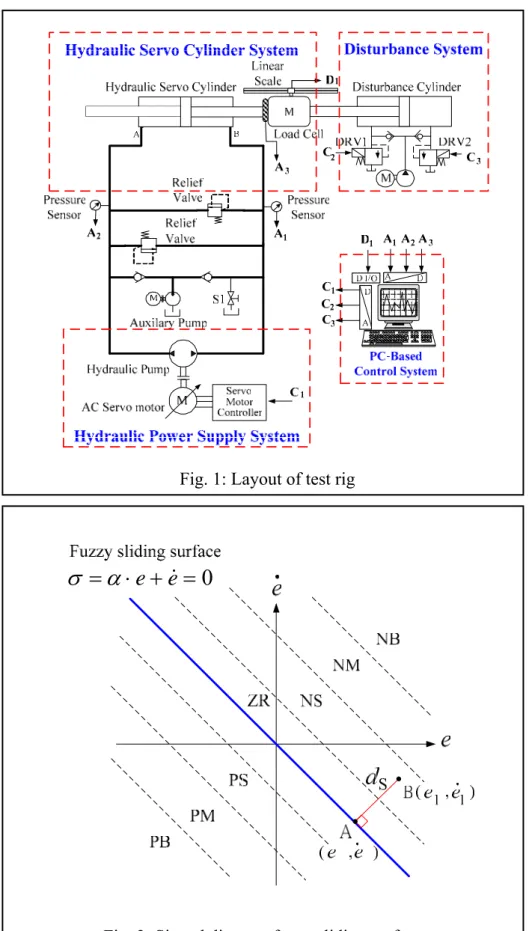
2. Layout of Experimental System The test rig in this work can be divided into three subsystems, including the hydraulic servo cylinder system, the hydraulic power supply system and the PC-based control system, as shown in Fig.1. The specifications of the main components are listed in Table 1. The hydraulic servo cylinder system contains a symmetrical cylinder fitted with a linear encoder with the resolution of 0,1 µm. The hydraulic power supply system, which consists of a swash plate axial piston pump with constant displacement of 12 ml/rev and is driven by an AC servo motor of 7.0 kW, adjusts the supply volume flow by the rotational speed controlled by the AC servo motor. The output control signals in RPM of the AC servo motor are given from the PC-based controller with the sampling time of 5 ms via D/A converters and enlarged by a servo amplifier. The force signal is measured by the load cell and fed back to the PC-based controller.
Therefore, the overall system contains an electro-hydraulic pump-controlled system controlled by variable rotational speed AC servo motor. Besides, the disturbance system, including a disturbance cylinder, two relief valves and a gear pump, is used here to generate external disturbance force by closing the two relief valves DRV1 and DRV2 for the different loading conditions of experiments.
3. Signed-Distance Fuzzy Sliding Mode Control
Conventional fuzzy control theory contains fuzzification, fuzzy rule base, fuzzy inference and defuzzification. In many fuzzy control systems, the fuzzy rule base depends on control error and control error rate that complicate the fuzzy inference rules and the membership functions. In order to reduce the fuzzy rules in fuzzy controller, fuzzy sliding mode controllers (FSMC) that combine fuzzy control theory with sliding mode control were quite developed [15]. In this paper, signed-distance fuzzy sliding mode control (SD-FSMC) [18] is used to design the hydraulic
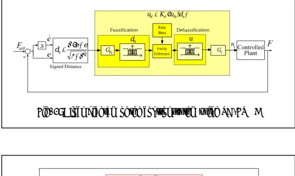
servo controller. In most traditional fuzzy sliding mode control, the 2-dimensional rule table has the skew-symmetric property, and the absolute magnitude of the control input is proportional to the distance from the main diagonal line on the phase plane. Therefore, the signed-distance d
e e&
s is introduced, which is the distance from the actual state to the sliding surface:
ZERO e
e+ =
⋅
=(α &)
σ (1) Note that the control inputs above and below the sliding surface have opposite signs.
Let A( , ) be the intersection point of the switching line and the line perpendicular to the switching line from an operating point B( , ), as illustrated in Fig.2. Thus, define the signed- distance d
e e&
e1 e&1
s for a general point B( , ) as: e1 e&1
2 2
1 1 2
1 1
1 1
) 1
sgn( α
σ α
α α σ α
= + +
+
= ⋅ +
+
= ⋅e e e e
dS & & (2)
where
⎩⎨
⎧
<
−
= >
0 1
0 ) 1
sgn( σ
σ σ
for
for (3)
Since the sign of the control input is negative for
ud
>0
σ and positive for σ <0 and its absolute magnitude is proportional to the distance ds from the line σ =0 , it can be concluded that:
s
d d
u ∝− (4) Thus, the fuzzy rule table can be established on an one-dimensional space of ds
instead of two-dimensional space of the e−e&
plane. That is, the control input can be determined only by ds instead of error and error rate .
e e&
By the SD-FSMC, the number of fuzzy rules can be considerably reduced and easily tuned. The sliding surface is divided into 7 sections by the membership function set of
( )d {NB,NM,NS,ZR,PS,PM,PB}
M s = , where
NB, NM, NS, ZR, PS, PM and PB are negative big, negative medium, negative small, zero,
4
positive small, positive medium and positive big respectively. The membership function set for the control input ud is defined as
( )u {PB,PM,PS,ZR ,NM,NB}.
M d = , NS
Therefore, instead of 7×7 fuzzy rules with cont
>
⋅
−
≤
≤
−
⋅
−
−
<
⋅
=
7 , 7
,
7 , 1
,
1 , 1
,
) (
S S S
d
S s S S
d
S S S
d s
d
d d for d
K
d d d for d
K
d d for d
d u
(5)
where
(6)
4. Controller Design
In this study, the variable rotational speed pum
oosing the suitable fuzzy slidi
rol error e and error rate e& in the conventional fuzzy control, the SD-FSMC can reduce the fuzzy rules into 7 rules via the signed-distance ds, as shown in Table 2. The Mamdani method is used in the fuzzy inference and the centroid method is used for defuzzification. Consequently, assume dS,1 and
7 ,
dS are the minimum and maximum lues ectively in the membership function set, i.e.
7 , 1
, s S
S d d
d ≤ ≤ . Fig.3 illustrates the block e control system of SD-FSMC.
The relationship between signed-distance d va resp
diagram of th
s and control input ud can be described as following:
⎧ K
⎪⎩
⎪⎨
) ( s
fs
d u d
K ⋅
=
⎪⎩
⎪⎨
⎧
>
−
≤
≤
−
−
−
<
=
7 , 7
,
7 , 1
,
1 , 1
,
) (
S S S
S s S S
S S S
s fs
d d for
d
d d d for d
d d for d
d u
p-controlled system controlled by SD-FSMC is implemented for force control.
The block diagram of the overall system is shown in Fig. 4 .
Through ch
ng surfaceσ , the scaling factors G and S G , parameter u K , and the memd rship
tions of d
be func s an ufs, the control input ud for the pump-controlle system can be decided.
Table 3 shows the control parameters and membership functions.
5. Expe
d d
riments
The forc igh response
aria
ferent step force
ure 5 indicates the experiment results of the
e control of the h
v ble rotational speed hydraulic pump-controlled system driven by the AC servo motor and the swash plate axial piston pump is implemented using SD-FSMC experimentally.
In order to verify the feasibility of the electro-hydraulic pump-controlled system and realize the response and the control performance, the force control is implemented on two experiments. The first, the experiment of the force control for three different step force inputs is implicated. After that, the force tracking control with sine wave force input is implemented. The external loading force is generated by the disturbance cylinder of the disturbance system by closing the relief valves DRV1 and DRV2. The control signals of the AC servo motor are transferred to RPM in the PC-based controller. The experiments are implemented on the mid-position of the stroke with sampling frequency 200 Hz. The oil temperature is about 30~40℃, and the maximum force generated from the servo cylinder is about 6780kgf.
5.1 Force control for dif inputs
Fig
force control response for different step force inputs, such as 3000kgf, 5000kgf, 6500kgf.
It shows that the rising times of the various force outputs are below 0.71 seconds, and the setting times also are controlled within 0.89 seconds for different step inputs. It is evident that the hydraulic pump-controlled servo system realizes the performance of high response. The steady-state errors, which are zoomed in as shown in Fig.6, are restricted within 100 kgf (1.5%~2.1%). It is obvious that the hydraulic pump-controlled servo system also performs well on accuracy. Fig.7(a) and 7(b) indicate the control output signals to the AC servo motor and the supply pressure to the cylinder respectively. They are verified that the force control of the hydraulic pump-controlled servo system requires adequate pressure supplied but very low output rotational speed. Consequently,
5
only low power is needed and the energy efficiency is high. Therefore, the hydraulic pump-controlled servo system realizes the performance of high response and high energy efficiency. The performances of the system under the three different test conditions are summarized in Table 4.
5.2 Force tracking control with sine wave
In the experiment a sine wave input with the a
6. Conclusions
1. This investigation developed a new
2. In the new electro-hydraulic pump-controlled
3. For achieving better force control
4. force control are
5. T system
6. is needed for the force
7. ntal result shows that the
. re, the new electro-hydraulic
9. The research results have been published in 3
References
[1] Murrenhoff H, “ Servohydrualik ” (in
] -J, “Neue
lektrohydraulisches force input
mplitude of 4000 kgf and the frequency of 0.1 Hz is implemented to evaluate the tracking performance of the hydraulic pump-controlled servo system. Fig.8 indicates that the phase lag is about 0.2 seconds over the full cycles except on the dead band of the cylinder motion, at that time hysteresis exists when the hydraulic cylinder changes moving direction. On the other hand, only a little deterioration at the peak of sine wave force output when the AC servo motor changes rotation direction. The experimental results show that the tracking performance is acceptable over the full cycles.
Fig.9(a) and 9(b) indicate the control output signals to the AC servo motor and the supply pressure to the cylinder respectively.
8
electro-hydraulic pump-controlled system driven by the AC servo motor for realizing force control with both high response and high energy-efficiency, instead of the integration control concept of the hydraulic valve-controlled systems developed in [5-7]
that are complicated and need more control hardware.
system, the swash plate constant displacement axial piston pump is used to combine with the AC servo motor, instead of the internal gear pump used in [8-14] due to its better response and efficiency.
[2
performance, sign-distance fuzzy sliding mode control, which has simplified fuzzy
rules and less computing time, is used and verified experimentally.
The experiments of
[3]
implemented for different force targets, such as 3000, 5000 and 6500 kgf. The experimental results show that the rising times are below 0.71 seconds and the setting times also are controlled within 0.89 seconds for various force outputs.
he hydraulic pump-controlled servo
performs well on accuracy with little steady-state errors controlled within 100 kgf (1.5%~2.1%).
Only low power
control of the hydraulic pump-controlled servo system.
The experime
tracking performance is acceptable over the full cycles with about 0.2 seconds phase lag except on the dead band of the cylinder motion.
Therefo
pump-controlled system driven by AC servo motor with variable rotational speed can simultaneously achieve the performance of high energy efficiency and high response for force control of hydraulic injection moulding machines.
master theses [19-21], 3 conference papers [22-24]. Besides, 6 journal papers [25-30]
have been submitted or prepared to different SCI-journals for reviewing.
German), Lecture notes, RWTH Aachen University, Germany, (1998).
Backé, W and Feigel H
Möglichkeiten beim Electro-hydraulischen Load-Sensing” (in German), O+P Ölhydraulik und Pneumatik 34, No.2, (1990), pp. 106-114.
Esders H, “E
Load-Sensing für Mobile Anwendungen”,
6
(in German), O+P Ölhydraulik und Pneumatik 36, Nr.8, (1994), pp.473-480.
Kim S-D, Cho H-S and Lee C-O, “Stabili
[4] ty
[5] Chien Y-W, “Parallel
[6] , Tsai J-J,
[7] hen Y-N and Yeh
[8] ulische
[9] “Elektro-hydraulische
[10] Feldmann D-G, “Ein
[11] of
[12] static drive –
[13] berg A, “Design of a
[14] Injection moulding machine
[15] Design of a Fuzzy
[16] igatos G-G, “A Simple
17] liding-Mode
[18] oo Kwak, and
[19] 滑動
H∞/QFT 控制應用於高響 Analysis of a Load-Sensing Hydraulic
System”, Proc. of the Institute of Mechanical Engineers, Part A: Power and Process Engineering, Vol.202, No.A2, (1988), pp.79-88.
Chiang M-H and
control of velocity control and energy-saving control on a hydraulic valve controlled system using self-organizing fuzzy sliding mode control”, JSME International Journal, Series C, Vol.46, No.1, (2003), pp.224-231.
Chiang M-H, Lee L-W
“Concurrent implementation of high velocity control performance and high energy-efficiency for hydraulic injection moulding machines”, International Journal of Advanced Manufacturing Technology, 23, (2004), pp.256–262.
Chiang M-H, Yang F-L, C
Y-P, “Integrated control of clamping force and energy-saving in hydraulic injection moulding machines using decoupling sliding-mode control”, International Journal of Advanced Manufacturing Technology 27, (2005), pp.53-62.
Helduser S, “Moderne hydra
Antriebe und Steuerungen am Beispiel von
Kunststoff-Spritgiessmaschinen” (in German), O+P Ölhydraulik und Pneumatik
39, No.10, (1995).
Ruhlicke I,
[
Antriebssysteme mit drehzahlveränderbarer Doppelpumpe”, (in
German), O+P Ölhydraulik und Pneumatik 41, No.10, (1997).
Kazmeier B and
neues Konzept füreinen kompakten elektrohydraulischen Linearantrieb” (in German), Proc. of 1. International Fluid Power Conference (1.IFK), Aachen, Germany, Band 1, (1998), pp.345-358,.
Bildstein A, “Application
[20]
electro-hydrostatic actuators (EHA) for
future aircraft primary flight control”, Proc.
of the 1. International Fluid Power Conference (1.IFK), Aachen, Germany, Band 1, (1998), pp.93-105,.
Helduser S, “Electric-hydro
an innovative energy-saving power and motion control system”, Proc. of Institution of Mechanical Engineers, Vol. 213, Part I, (1999), pp.427-439.
Habibi S and Golden
new high performance electro-hydraulic actuator”, Proc. of the 1999 IEEE/ASME International Conference on Advanced Mechatroics, Atlanta, USA, (1999), pp.227-232.
Helbig A, “
with electric-hydrostatic drives”, Proc. of the 3. International Fluid Power Conference (3. IFK), Aachen, Germany, Vol.1, (2002), pp.67-82.
Kim, S-W and Lee J-J, “
Controller with Fuzzy Sliding Surface”, Fuzzy Sets & Systems, Vol.71, No.3, (1995), pp.359-67.
Tzafestas S-G. and R
Robust Sliding Mode Fuzzy-Logic Controller of the Diagonal Type”, Journal of Intelligent & Robotic Systems, Vol.26, No.3-4, (1999), pp. 353-388.
Wu J-C and Liu T-S, “A S
Approach to Fuzzy Control Design”, IEEE Trans. Control Systems Technology, vol.4, no.2, (1996), pp. 141-151.
Byung-Jae Choi, Seong-W
Byung Kook Kim “Design of a single-input fuzzy logic controller and its properites” Fuzzy Sets and Systems pp.299-308 1999.
劉憲學,以距離基礎之適應性模糊 模式控制應用於高響應泵控液壓伺服系 統之研究,國立 台灣科技大學碩士論 文,2005。
張豐霖,結合
應泵控液壓伺服系統之研究,國立台灣 科技大學碩士論文,2005。
7
[21] 式控制應用
[22] M.H, Lee, L.-W.*, Liu, H.H *,
[23] iu, H.H.*,
[24] 應泵控液壓伺服系
[25] N and Mao-Hsiung
[26] iung
[27] h CHEN and Mao-Hsiung
[28] Lian-Wang Lee,
[29]
Liou, Distance-Based
[30]
ang, High Response Hydraulic 吳宗修,適應性模糊滑動模
於高響應泵控液壓伺服系統力量控制之 研 究 , 國立 台灣科技大學碩士論 文 , 2006。
Chiang,
距離基礎之直接自適應模糊滑模控制及 其在高響應泵控液壓伺服系統之應用,
The 22nd National Conference on Mechanical Engineering of the Chinese Society of Mechanical Engineers, Taoyuan, Taiwan (Nov. 25.-26., 2005).
Chiang, M.H, Chen, C.-C.*, L
高響應液壓泵控伺服系統應用於定位控 制 – 以 AC 伺 服 馬 達 實 現 , The 22nd National Conference on Mechanical Engineering of the Chinese Society of Mechanical Engineers, Taoyuan, Taiwan (Nov. 25.-26., 2005).
江茂雄、陳宗傑*,響
統應用於射出成形機之力量控制–以 AC 伺服馬達實現,中國機械工程學會第二 十三屆全國學術研討會,台南,Taiwan, (Nov.24-25, 2006).
Chung-Chieh CHE
CHIANG, The High Response and High Efficiency Electro-Hydraulic Pump- Controlled System Using an AC Servo Motor for Force Control in Hydraulic Injection Moulding Machines, submit to International Journal of Advanced Manufacturing Technology (SCI, EI).
Chung-Chieh CHEN and Mao-Hs CHIANG, The High Response and High Efficiency Electro-Hydraulic Pump- Controlled System Using an AC Servo Motor for Velocity Control in Hydraulic Injection Moulding Machines, in prepration.
Chung-Chie
CHIANG, High Response Hydraulic Pump-Controlled System Using Signed-Distance Fuzzy Sliding Mode Control, in prepration.
Mao-Hsiung Chiang,
Hsien-Hsieh Liou, Adaptive Fuzzy Sliding-Mode Control for Variable
Displacement Hydraulic servo systems, in preparation.
Mao-Hsiung Chiang, Lian-Wang Lee, Hsien-Hsieh
Adaptive Fuzzy Sliding-Mode Control for a Novel Pump Control Hydraulic servo systems with Rotational speed control, in preparation.
Mao-Hsiung Chiang, Lian-Wang Lee, Fong-Lin Ch
Pump-Controlled Servo Systems via H∞ and QFT Control, in preparztion.
8
Fig. 1: Layout of test rig
=0 +
⋅
=
α e e
&σ
Fig. 2: Signed distance fuzzy sliding surface
9
1 α2
α +
+
= ⋅e e ds
&
dS
G Gu
S u d
) ( s
fs d
d K u d
u = ⋅
Fig. 3: Block diagram of the control system using SD-FSMC
SD-FSMC Force Controller
Servo AC Motor
Hydraulic Pump
Hydraulic Servo Cylinder
F Fset
+ _
Force Hydraulic Power
Supply System
Electronic Hydraulic u
Fig. 4: Block diagram of force control in hydraulic pump controlled cylinder system via AC servo motor
0 0.5 1 1.5 2 2.5 3 3.5 4
0 1000 2000 3000 4000 5000 6000 6500 7000
Variable Speed Pump-control : Force Control with Step Input Force
Runtime (sec)
Force (kgf)
6500kgf 5000kgf 3000kgf
Fig.5: Experimental results of force control on different step force inputs
10
0 0.5 1 1.5 2 2.5 3 3.5 4 -100
0 100 200 300 400 500
Variable Speed Pump-control : Force Control with Step Input Force
Runtime (sec)
Error Zoom (kgf)
6500kgf 5000kgf 3000kgf
Fig.6: Zoom in of control error on different step force inputs
0 0.5 1 1.5 2 2.5 3 3.5 4
0 100 200 300 400
(a)
Output Speed (RPM)
Runtime (sec)
0 0.5 1 1.5 2 2.5 3 3.5 4
0 50 100 150 200
Runtime (sec)
Pressure (kgf/cm2)
(b)
6500kgf 5000kgf 3000kgf 6500kgf 5000kgf 3000kgf
Fig.7: (a) Control output of AC servo motor rotational speeds for different force targets (b) Supply pressure variations for different force targets
11
0 2 4 6 8 10 12 14 16 18 20 -4000
-3000 -2000 -1000 0 1000 2000 3000 4000
Variable Speed Pump-control : Force Control with Sine Wave Force Input
Runtime (sec)
Force (kgf)
Target Force Error
Fig.8: Experimental results of force tracking control
0 5 10 15 20
-200 -100 0 100 200
(a)
Output Speed (RPM)
Rumtime (sec)
0 5 10 15 20
-200 -100 0 100 200
Runtime (sec)
Pressure (kgf/cm2)
(b)
(PA -PB)
Fig.9: (a) Control output of AC servo motor rotational speeds for force tracking control (b) Supply pressure variations for force tracking control
12
Table 1: Main components’ specifications of the test rig Components Specifications
AC servo motor Input : 3ψ 220V
Rated rotational speed: 2000 rpm Rated output: 7.0kW
Servo motor driver
Input voltage: 200~230V FLC: 46A
Output freq.:0~ 200Hz
Output power: 7.5 kW
Hydraulic pump
Swash plate axial piston pump Max. pressure: 400 kgf/cm2 Fixed displacement: 12 ml/rev Max. rotational speed: 8000 rpm Direction of flow: reversible Hydraulic servo
cylinder
Max. pressure: 210 kgf/cm2 Max. stroke: 400mm Piston diameter: 80mm Rod diameter:45mm Disturance cylinder
Max. pressure: 210 kgf/cm2 Max. stroke: 400mm Piston diameter: 80mm Rod diameter:45mm Optical encoder Range: 500 mm
Decoder: PCL-833 Resolution: 0,1 µm Load cell Range: 11340kgf/10V PC-based controller AMD K6-2 450 CPU
RAM: 512MB
A/D D/A cards
(a)PCL-818H 12 bit A/D×16 CH 12 bit D/A×1 CH D/I、D/O×16 (b)PCL-726 12 bit D/A×6 CH D/I、D/O×16 CH
13
Table 2: Rule table of SD-FSMC
d
s NB NM NS ZE PS PM PBu
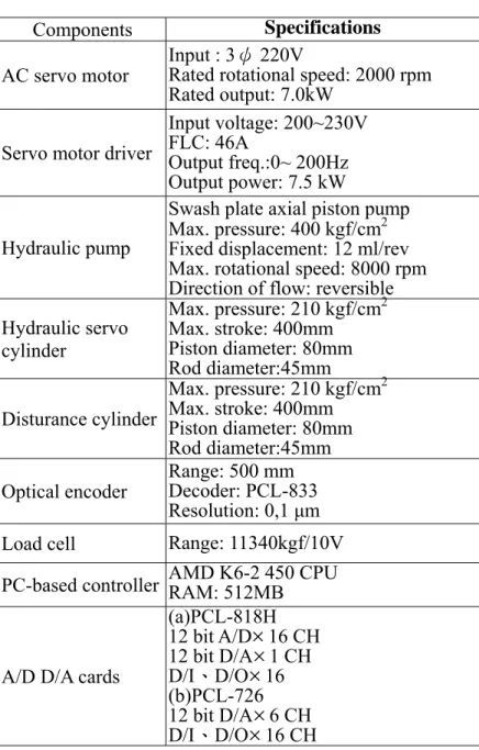
d PB PM PS ZE NS NM NBTable 3: Control parameters of SD-FSMC for force controller Control input
u
C =K
d ⋅u
fs(d
s)Parameters α
G
sG
uK
dvalues 3.2 0.00005 1 400
Membership of )
(dS
M
M
(d
S)=[ 1.0 0.66 0.33 0.0 -0.33 -0.66 -1.0 ] Membership of) ( S
fs d
u
u
fs(d
S)=[ -1.0 -0.28 -0.08 0.0 0.08 0.28 1.0 ]Table 4: System performance of force control for different step force inputs
Force targets 3000kgf 5000kgf 6500kgf Rising time
tr (10~90%) 0.55 sec
0.71 sec
0.66 sec Setting time
( 2%)
t es < 0.86 sec
0.89 sec
0.80 sec Steady state error
ess
64 kgf
(2.1%) 100 kgf
(2.0%) 100 kgf (1.5%)
14
![Table 3: Control parameters of SD-FSMC for force controller Control input u C = K d ⋅ u fs ( d s ) Parameters α G s G u K d values 3.2 0.00005 1 400 Membership of )(d SM M ( d S ) =[ 1.0 0.66 0.33 0.0 -0.33 -0.66 -1.0 ] Membership of )( Sfs](https://thumb-ap.123doks.com/thumbv2/9libinfo/9128892.412972/15.892.109.787.362.598/table-control-parameters-controller-control-parameters-membership-membership.webp)
